PR 5114 User manual

5114
Programmable
Transmitter
No. 5114V107-UK
From ser. no. 990061001

1630
PR electronics A/S tilbyder et bredt program af analoge og digitale
signalbehandlingsmoduler til industriel automation. Programmet
består af Isolatorer, Displays, Ex-barrierer, Temperaturtransmittere,
multifunktionelle transmittere mfl. Vi har modulerne, du kan stole
på i selv barske miljøer med elektrisk støj, vibrationer og tempera-
turudsving, og alle produkter opfylder de strengeste internationale
standarder. Vores motto »Signals the Best« er indbegrebet af denne
filosofi – og din garanti for kvalitet.
PR electronics A/S oers a wide range of analog and digital signal
conditioning devices for industrial automation. The product range
includes Isolators, Displays, Ex Interfaces, Temperature Transmitters,
and Multifunctional Devices. You can trust our products in the
most extreme environments with electrical noise, vibrations and
temperature fluctuations, and all products comply with the most
exacting international standards. »Signals the Best« is the epitome
of our philosophy – and your guarantee for quality.
PR electronics A/S ore une large gamme de produits pour le traite-
ment des signaux analogiques et numériques dans tous les domaines
industriels. La gamme de produits s’étend des transmetteurs
de température aux acheurs, des isolateurs aux interfaces SI,
jusqu’aux modules multifonctions. Vous pouvez compter sur nos
produits même dans les conditions d’utilisation sévères, p.ex.
bruit électrique, vibrations et fluctuations de température. Tous
nos produits sont conformes aux normes internationales les plus
strictes. Notre devise »SIGNALS the BEST« c’est notre ligne de
conduite - et pour vous l’assurance de la meilleure qualité.
PR electronics A/S verfügt über ein breites Produktprogramm
an analogen und digitalen Signalverarbeitungsgeräte für die in-
dustrielle Automatisierung. Dieses Programm umfasst Displays,
Temperaturtransmitter, Ex- und galvanische Signaltrenner, und
Multifunktionale Geräte. Sie können unsere Geräte auch unter
extremen Einsatzbedingungen wie elektrisches Rauschen,
Erschütterungen und Temperaturschwingungen vertrauen, und
alle Produkte von PR electronics werden in Übereinstimmung mit
den strengsten internationalen Normen produziert. »Signals the
Best« ist Ihre Garantie für Qualität!
DK
UK
FR
DE

5114V107-UK 1
PROGRAMMABLE TRANSMITTER
5114
CONTENTS
Warning....................................................................................................... 2
Symbol identification............................................................................ 3
Safety instructions................................................................................. 3
How to demount system 5000 ........................................................ 5
Application................................................................................................. 6
Technical characteristics...................................................................... 6
Input types................................................................................................ 6
Output......................................................................................................... 7
Configuration............................................................................................ 8
Electrical specifications........................................................................ 8
Order ............................................................................................................ 13
5114 connection to Loop Link.......................................................... 13
Block diagram........................................................................................... 14
Selection of input type: (5114A)..................................................... 15

2 5114V107-UK
WARNING
This device is designed for connection to hazardous electric
voltages. Ignoring this warning can result in severe personal injury
or mechanical damage.
To avoid the risk of electric shock and fire, the safety instructions
of this manual must be observed and the guidelines followed. The
specifications must not be exceeded, and the device must only be
applied as described in the following.
Prior to the commissioning of the device, this manual must be
examined carefully. Only qualified personnel (technicians) should
install this device. If the equipment is used in a manner not
specified by the manufacturer, the protection provided by the
equipment may be impaired.
WARNING
Until the device is fixed, do not connect hazardous voltages to
the device.
The following operations should only be carried out on a
disconnected device and under ESD safe conditions:
Dismantlement of the device for setting of DIP-switches
and jumpers.
General mounting, connection and disconnection of wires.
Troubleshooting the device.
Repair of the device and replacement of circuit breakers must
be done by PR electronics A/S only.
WARNING
SYSTEM 5000 must be mounted on DIN rail according to DIN
46277.
The communication connector of SYSTEM 5000 is connected to
the input terminals on which dangerous voltages can occur, and it
must only be connected to the programming unit Loop Link by way
of the enclosed cable.
HAZARDOUS
VOLTAGE
INSTAL-
LATION
GENERAL

5114V107-UK 3
SYMBOL IDENTIFICATION
Triangle with an exclamation mark: Warning / demand.
Potentially lethal situations.
The CE mark proves the compliance of the device with the essential
requirements of the directives.
The double insulation symbol shows that the device is protected by
double or reinforced insulation.
Ex devices have been approved for use in connection with installations
in explosive areas.
SAFETY INSTRUCTIONS
DEFINITIONS
Hazardous voltages have been defined as the ranges: 75 to 1500 Volt DC, and
50 to 1000 Volt AC.
Technicians are qualified persons educated or trained to mount, operate, and also
troubleshoot technically correct and in accordance with safety regulations.
Operators, being familiar with the contents of this manual, adjust and operate the
knobs or potentiometers during normal operation.
RECEIPT AND UNPACKING
Unpack the device without damaging it. The packing should always follow the
device until this has been permanently mounted. Check at the receipt of the device
whether the type corresponds to the one ordered.
ENVIRONMENT
Avoid direct sunlight, dust, high temperatures, mechanical vibrations and shock, as
well as rain and heavy moisture. If necessary, heating in excess of the stated limits
for ambient temperatures should be avoided by way of ventilation.
All devices fall under Installation Category II, Pollution Degree 1, and Insulation
Class II.

4 5114V107-UK
MOUNTING
Only technicians who are familiar with the technical terms, warnings, and
instructions in the manual and who are able to follow these should connect the
device. Should there be any doubt as to the correct handling of the device, please
contact your local distributor or, alternatively,
PR electronics A/S
www.prelectronics.com
Mounting and connection of the device should comply with national legislation for
mounting of electric materials, i.e. wire cross section, protective fuse, and location.
Descriptions of input / output and supply connections are shown in the block
diagram and side label.
The following apply to fixed hazardous voltages-connected devices:
The max. size of the protective fuse is 10 A and, together with a power
switch, it should be easily accessible and close to the device. The power
switch should be marked with a label telling it will switch off the voltage
to the device.
Year of manufacture can be taken from the first two digits in the serial number.
CALIBRATION AND ADJUSTMENT:
During calibration and adjustment, the measuring and connection of external
voltages must be carried out according to the specifications of this manual. The
technician must use tools and instruments that are safe to use.
NORMAL OPERATION:
Operators are only allowed to adjust and operate devices that are safely fixed in
panels, etc., thus avoiding the danger of personal injury and damage. This means
there is no electrical shock hazard, and the device is easily accessible.
CLEANING:
When disconnected, the device may be cleaned with a cloth moistened with
distilled water.
LIABILITY:
To the extent the instructions in this manual are not strictly observed, the customer
cannot advance a demand against PR electronics A/S that would otherwise exist
according to the concluded sales agreement.

5114V107-UK 5
Picture 3: Access to programming
connector.
Picture 1: Separation from DIN rail.
Picture 2: Removal of PCB.
HOW TO DEMOUNT SYSTEM 5000
First, remember to demount the connectors with hazardous voltages. By lifting the
bottom lock, the device is detached from the DIN rail as shown in picture 1.
Then, by lifting the upper lock and pulling the front plate simultaneously the PCB
is removed as shown in picture 2.
Switches and jumpers can now be adjusted. By opening the front, the programming
connector is accessible as shown in picture 3.

6 5114V107-UK
PROGRAMMABLE TRANSMITTER 5114
• Input for RTD, TC, mV, linear resistance, mA, and V
• 3-port 3.75 kVAC galvanic isolation
• Current and voltage output
• Universal voltage supply
• 1- and 2-channel versions
• Loop supply > 17.1 V in Ex zone 0
APPLICATION
Electronic temperature measurement with resistance sensor or thermocouple
sensor. • Ex barrier for temperature sensors, potentiometers, and current / voltage
signals •Ex power supply for 2-wire transmitters in zone 0, 1, 2, 20, 21, and
22. • Amplification of mV signals. • Conversion of linear resistance variation.
• Galvanic isolation of analogue signals. • Measurement of floating signals.
• Linearisation of non-linear Ohm, mV, mA, or voltage signals. • Separation of circuits
in PELV/SELV installations. • The transmitter is especially suitable for emitting the
output current signal, either as a standard current signal or as a loop signal.
TECHNICAL CHARACTERISTICS
The unit is based on a microprocessor core with an efficient program operation.
The basic calibration data and present set-up are stored in an EEPROM thereby
avoiding the loss or change of data at power off. The 2-channel version has a full
galvanic isolation between the channels. By way of jumpers on the PCB the input
in the standard version can be programmed either for a temperature or a current /
voltage input. This means that one channel can work as for instance a temperature
transmitter and the other can work as an isolation amplifier. Measurement range,
signal parameters, and output span are configured to the present task by way of a
PC and PR electronics A/S’ communications interface Loop Link.
INPUT TYPES
Temperature input - jumpers in position 1:
Thermocouple input (TC) for standard thermocouples type B, E, J, K, L, N, R, S, T, U,
W3, W5, LR according to the norms IEC 584, DIN 43710, ASTM E988-90 and GOST
3044-84. The CJC can be selected in 3 different ways: internally in the terminal,
externally by way of a Pt100 / Ni100 sensor, or externally with a constant
temperature.

5114V107-UK 7
If internal compensation is selected, a terminal with a built-in temperature sensor
must be ordered separately (PR type no. 5910 and 5913). Sensor error detection
is available.
RTD input for Pt100...Pt1000 according to the norm IEC 751 and Ni100...Ni1000
according to the norm DIN 43760.
Automatic cable compensation at a 3- or 4-wire connection. At a 2-wire connection
the cable resistance can be entered or measured by the configuration program
and sent to the device which then compensates by the entered cable resistance.
Sensor error detection is available.
Resistance input for resistance measurement with cable compensation as
described under the RTD input. Sensor error detection is available.
The mV input is programmable in the range -150...+150 mV.
Current / voltage input - jumpers in position 2:
The current input is programmable in the range 0...100 mA, for instance 4...20
mA.
The voltage input is programmable in the range 0...250 VDC.
Auxiliary supplies are selected in the configuration program:
Loop transmitter supply > 17.1 VDC.
Reference voltage of 2.5 VDC, for instance as a supply for potentiometers.
OUTPUT
The analogue standard current / voltage output is programmable in the range 0...20
mA, for instance 4...20 mA and 0...10 VDC. The output voltage can be ordered for a
maximum of 12 VDC by a special shunt resistance. The output signal is proportional
and linear to the value of the input signal. Special set-ups can be selected in the
configuration program, for instance a customised linearisation, a reversed output,
a limiter according to the selected output span, and selection of an output value
in case of a sensor error. Maximum load on the current output is 600 Ω. Minimum
load on the voltage output is 500 kΩ.
Loop 4...20 mA current output:
By wiring the current signal alternatively, the output works as a loop output. If
the supply voltage for the 5114 disappears, the output current drops to < 4 mA.
Sensor error detection:
The output can be set up at an RTD, thermocouple and linear resistance input to go
to max., to min. or entered value at sensor error detection. If the output is set to 4…20
mA it is also possible to select NAMUR NE43 Upscale or Downscale.

8 5114V107-UK
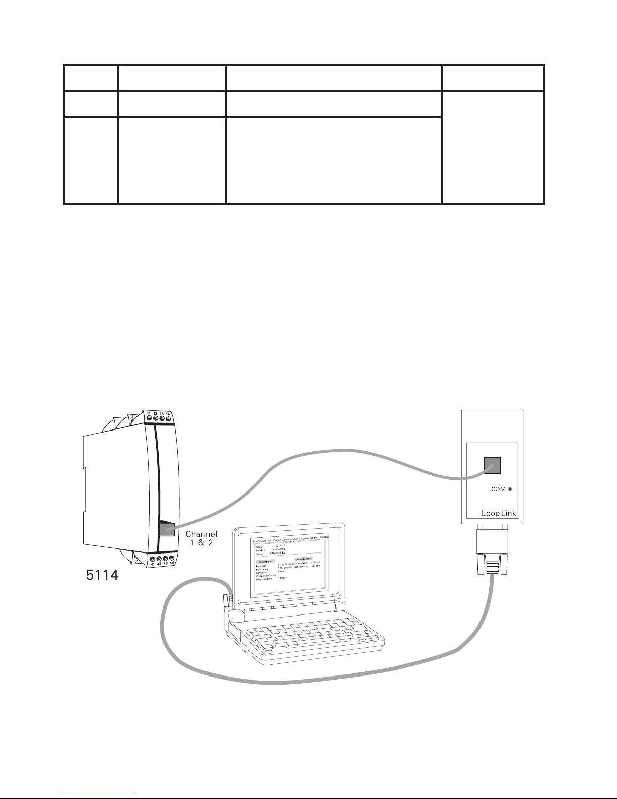
CONFIGURATION
The transmitter is configured to the present task by way of a PC and PR
electronics A/S’ communications interface Loop Link. The communications interface
is galvanically isolated to protect the PC port. Communication is 2-way to allow the
retrieval of the transmitter set-up into the PC and to allow the transmission of the
PC set-up to the transmitter. For users who do not wish to do the set-up them-
selves, the 5114 can be delivered configured according to customer specifications:
input type, measurement range, sensor error detection, and output signal.
ELECTRICAL SPECIFICATIONS
Specifications range:
-20°C to +60°C
Common specifications:
Supply voltage, universal..................................... 21.6...253 VAC
50...60 Hz
19.2...300 VDC
Max. required power, 1 / 2 channels ............... 2.1 W / 2.8 W
Fuse............................................................................... 400 mA SB / 250 VAC
Isolation voltage, test / operation.................... 3.75 kVAC / 250 VAC
PELV/SELV .................................................................. IEC 61140
Communications interface ................................... Loop Link
Signal / noise ratio .................................................. Min. 60 dB (0...100 kHz)
Updating time:
Temperature input............................................. 115 ms
mA / V / mV input.............................................. 75 ms
Response time (0...90%, 100...10%), programmable:
Temperature input............................................. 400 ms...60 s
mA / V / mV input.............................................. 250 ms...60 s
Signal dynamics, input........................................... 22 bit
Signal dynamics, output ....................................... 16 bit
Calibration temperature ........................................ 20...28°C

5114V107-UK 9
Accuracy, the greater of the general and basic values:
Auxiliary supplies:
Reference voltage................................................... 2.5 VDC ±0.5% / 15 mA
2-wire supply (pin 44...42 and 54...52).......... 28...17.1 VDC / 0...20 mA
Max. wire size............................................................ 1 x 2.5 mm2stranded wire
Screw terminal torque ........................................... 0.5 Nm
Relative humidity..................................................... < 95% RH (non-cond.)
Dimensions (HxWxD).............................................. 109 x 23.5 x 130 mm
DIN rail type............................................................... DIN 46277
Protection degree.................................................... IP20
Weight .......................................................................... 225 g
EMC immunity influence.................................................. < ±0.5% of span
Extended EMC immunity:
NAMUR NE 21, A criterion, burst ................................. < ±1% of span
General values
Input type Absolute
accuracy Temperature
coefficient
All ≤±0.05% of span ≤±0.01% of span / °C
Basic values
Input type Basic
accuracy Temperature
coefficient
mA ≤±4 µA ≤±0.4 µA / °C
Volt ≤±10 µV ≤±1 µV / °C
RTD ≤±0.2°C ≤±0.01°C / °C
Lin. resistance ≤±0.1 Ω ≤ ±10 mΩ/ °C
TC type:
E, J, K, L, N, T, U ≤±1°C ≤±0.05°C / °C
TC type: B, R, S,
W3, W5, LR ≤±2°C ≤±0.2°C / °C

10 5114V107-UK
Electrical specifications, temperature input:
TC input:
Max. offset ................................................................. 50% of selec. max. value
Sensor error current................................................ Nom. 30 µA
CJC .................................................................................. ≤±1°C
Sensor error detection........................................... Yes
mV input:
Measurement range................................................ -150...+150 mV
Min. measurement range...................................... 5 mV
Max. offset ................................................................. 50% of selec. max. value
Input resistance........................................................ Nom. 10 MΩ
RTD and linear resistance input:
Max. offset ................................................................. 50% of selec. max. value
Max. cable resistance per wire........................... 10 Ω
Sensor current........................................................... Nom. 0.2 mA
Effect of sensor cable resistance
(3- / 4-wire)................................................................ < 0.002 Ω / Ω
Sensor error detection........................................... Yes
Type Min. value Max. value Min. span Standard
Pt100
Ni100
Lin. R
-200°C
-60°C
0 Ω
+850°C
+250°C
5000 Ω
25°C
25°C
30 Ω
IEC 751
DIN 43760
-------
Type Min.
temperature Max.
temperature Min.
span
Standard
B
E
J
K
L
N
R
S
T
U
W3
W5
LR
+400°C
-100°C
-100°C
-180°C
-100°C
-180°C
-50°C
-50°C
-200°C
-200°C
0°C
0°C
-200°C
+1820°C
+1000°C
+1200°C
+1372°C
+900°C
+1300°C
+1760°C
+1760°C
+400°C
+600°C
+2300°C
+2300°C
+800°C
200°C
50°C
50°C
50°C
50°C
100°C
200°C
200°C
50°C
75°C
200°C
200°C
50°C
IEC584
IEC584
IEC584
IEC584
DIN 43710
IEC584
IEC584
IEC584
IEC584
DIN 43710
ASTM E988-90
ASTM E988-90
GOST 3044-84

5114V107-UK 11
Electrical specifications, mA / V / mV input:
Current input:
Measurement range................................................ 0...100 mA
Min. measurement range (span)........................ 4 mA
Max. offset ................................................................. 50% of selec. max. value
Input resistance:
Supplied unit........................................................ Nom. 10 Ω+ PTC 10 Ω
Non-supplied unit .............................................. RSHUNT = ∞, VDROP < 6 V
Voltage input:
Measurement range................................................ 0...250 VDC
Min. measurement range (span)........................ 5 mVDC
Max. offset ................................................................. 50% of selec. max. value
Input resistance ≤2.5 VDC ................................. Nom. 10 MΩ
> 2.5 VDC................................. Nom. 5 MΩ
Electrical specifications - OUTPUT:
Current output:
Signal range (span) ................................................. 0...20 mA
Min. signal range (span)........................................ 10 mA
Max. offset ................................................................. 50% of selec. max. value
Load............................................................................... ≤ 600 Ω
Load stability............................................................. ≤0.01% of span / 100 Ω
Current limit ............................................................... ≤28 mA
Voltage output:
Signal range (span) ................................................. 0...10 VDC
Min. signal range (span)........................................ 500 mV
Max. offset ................................................................. 50% of selec. max. value
Load............................................................................... ≥ 500 kΩ
2-wire 4...20 mA output:
Signal range............................................................... 4...20 mA
Load stability............................................................. ≤ 0.01% of span / 100 Ω
Load resistance......................................................... ≤ (Vsupply-3.5) / 0.023 A [Ω]
Max. external 2-wire supply ............................... 29 VDC
Effect of external 2-wire supply
voltage change......................................................... < 0.005% of span / V
Sensor error detection:
Programmable........................................................... 0...23 mA
NAMUR NE43 Upscale........................................... 23 mA
NAMUR NE43 Downscale..................................... 3.5 mA
No function ................................................................ Not defined

12 5114V107-UK
EEx / I.S. approval (5114B):
DEMKO 99ATEX124571....................................... II (1) GD
[EEx ia] IIC
Applicable in .............................................................. Zone 0, 1, 2, 20, 21 or 22
Ex / I.S. data for 5114B, all types:
Terminal 31, 32, and 33
Um.................................................................................. : 250 V
Ex / I.S. data for 5114 B1 (channel 1 for 5114B3):
Terminal 41, 42, 44 to 43 (51, 52, 54 to 53)
Uo................................................................................... : 7.5 VDC
Io..................................................................................... : 6.0 mADC
Po.................................................................................... : 11.25 mW
Lo.................................................................................... : 200 mH
Co.................................................................................... : 6.0 μF
Ex / I.S. data for 5114 B2 (channel 2 for 5114B3):
Terminal 44 to 41 (54 to 51)
Uo................................................................................... : 28 VDC
Io..................................................................................... : 87 mADC
Po.................................................................................... : 0.62 W
Lo.................................................................................... : 4.2 mH
Co.................................................................................... : 0.08 μF
Terminal 42, 43 to 41 (52, 53 to 51)
Uo................................................................................... : 7.5 VDC
Io..................................................................................... : 6.0 mADC
Po.................................................................................... : 11.25 mW
Lo.................................................................................... : 200 mH
Co.................................................................................... : 6.0 μF
Marine approval:
Det Norske Veritas, Ships & Offshore ............. Standard for Certification No. 2.4
Ex / I.S. approval:
ATEX 2014/34/EU................................................... DEMKO 99ATEX124571
EAC Ex TR-CU 012/2011 ..................................... RU C-DK.GB08.V.00410
Observed authority requirements:
EMC................................................................................ 2014/30/EU
RoHS ............................................................................. 2011/65/EU
LVD................................................................................. 2014/35/EU
EAC................................................................................. TR-CU 020/2011
Of span = Of the presently selected range
5114V107-UK 13
ORDER
5114 CONNECTION TO LOOP LINK
Note! For TC inputs with internal CJC, remember to order the CJC connectors type
5910 / 5910 Ex (ch. 1) and 5913 / 5913 Ex (ch. 2).
Type Version Input Channels
5114 Standard : A RTD / TC / R / mA / V / mV : - Single : A
Double : B
ATEX Ex : B RTD / TC / mV / R : 1
mA / V / mV : 2
Channel 1, RTD / TC / mV / R : 3
Channel 2, mA / V / mV
14 5114V107-UK
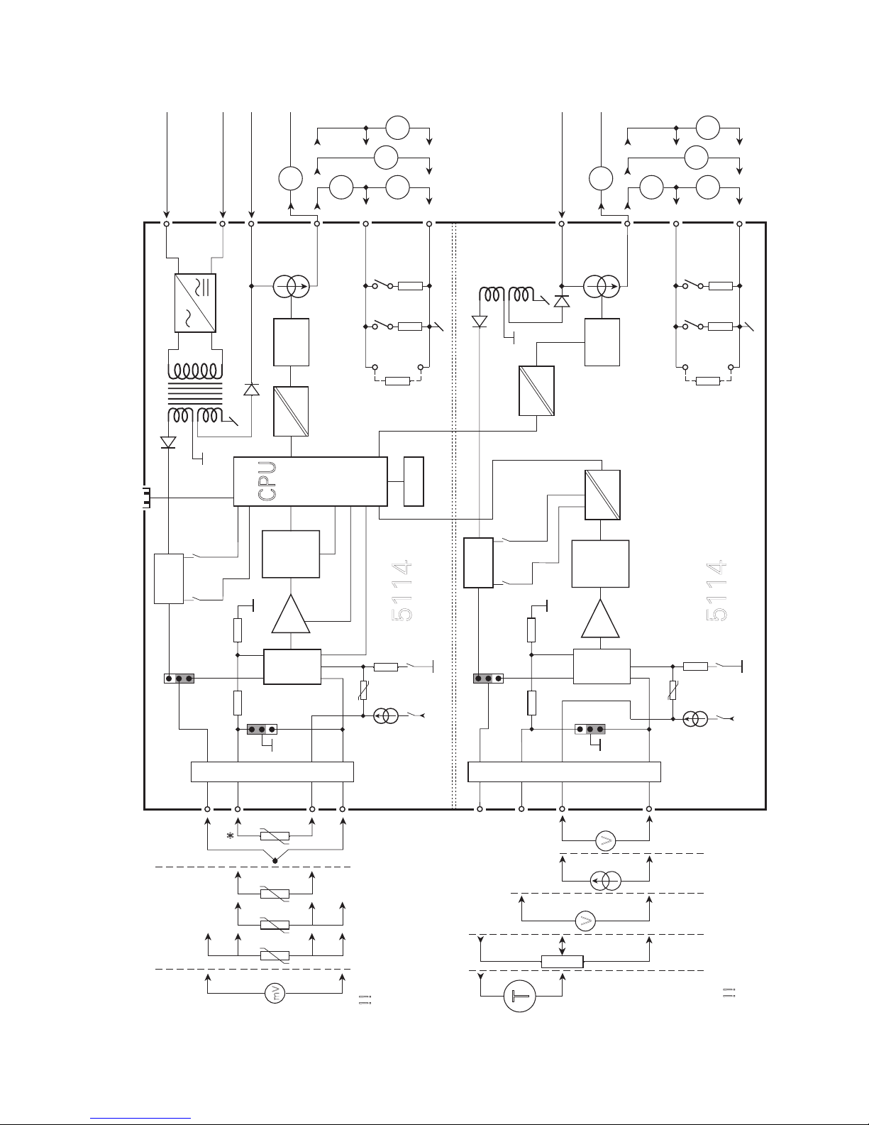
BLOCK DIAGRAM
5114
11
12
13
500
50
DP1 V +
GND.
gnd.
MUX
VV
A
A
CPU
EEPROM
A / D
PGA
21
33
31
14
I +
A
CH 1
CH 2
mA
Vreg.
+
-
V
+
-
+
-
V
-
+
T
PTC
50 k
21
22
23
500
50
DP2
I +
V +
VV
A
A
A
21
24
JP 1
2
0,2 mA
5114
+V
43
44
42
41
*
+
-
+
-
432
mV
5 M
1
1
2
JP 2
10 Ω
+V
JP 4
MUX
A / D
PGA
Vreg.
PTC
50 k
JP 3
2
0,2 mA
5 M
1
1
2
10 Ω
4...20 mA
4...20 mA
D / A
D / A
51
54
53
52
Input +
Input +,
> 2.5 V
Channel 2
Channel 1
mV TC
Front comm.
Supply
24...230 VAC &
24...250 VDC
2.5 V
2.5 V
Spec.
Output
V
Spec.
Output
V
RTD and lin. R
Conn. wire
2-wire
transm
.
3-wire
potm.
Loop supply / Vref.
Input gnd.
I + V
Out
I + V
Out
I
Out
I
Out
V
Out
V
Out
2-wire output sup. +
2-wire output sup. +
2-wire output sup. -
2-wire output sup. -
Supply
Loop sup.
> 17.1 V
Loop sup.
> 17.1 V
Analogue
Switch
Analogue
Switch
* Accessories: 5910 CJC connector CH 1, 5913 CJC connector CH 2.
Channel
1 shown as a
temperature
input:
!! If channel 2, use
terminal
no. 54...51
!! If channel 1, use
terminal
no. 44...41
Channel
2 shown as a
curren
t / voltage input:
V <=
2.5
V >
2.5
Ex barrier, only 5114BEx barrier, only 5114B

5114V107-UK 15
SELECTION OF INPUT TYPE: (5114A)
Input JP 1 JP 2 JP 3 JP 4
Temperature channel 1
Temperature channel 2
1
-
1
-
-
1
-
1
Current / voltage channel 1
Current / voltage channel 2
2
-
2
-
-
2
-
2

Programmable displays with a wide
selection of inputs and outputs for display of temperature,
volume and weight, etc. Feature linearization, scaling, and
dierence measurement functions for programming via
PReset software.
Displays
A wide selection of transmitters for DIN
form B mounting and DIN rail devices with analog and
digital bus communication ranging from application-
specific to universal transmitters.
Temperature
Galvanic isolators for analog and digital
signals as well as HART signals. A wide product range
with both loop-powered and universal isolators featuring
linearization, inversion, and scaling of output signals.
Isolation
Interfaces for analogue and digital signals
as well as HART signals between sensors / I/P converters /
frequency signals and control systems in Ex zone 0, 1 & 2
and for some devices in zone 20, 21 & 22.
Ex interfaces
PC or front programmable devices with
universal options for input, output and supply. This range
oers a number of advanced features such as process
calibration, linearization and auto-diagnosis.
Multifunctional

www.prelectronics.fr
sales-fr@prelectronics.com
www.prelectronics.de
sales-de@prelectronics.com
www.prelectronics.es
sales-es@prelectronics.com
www.prelectronics.it
sales-it@prelectronics.com
www.prelectronics.se
sales-se@prelectronics.com
www.prelectronics.com
sales-uk@prelectronics.com
www.prelectronics.com
sales-us@prelectronics.com
www.prelectronics.cn
sales-cn@prelectronics.com
www.prelectronics.be
sales-be@prelectronics.com
Head oce
Denmark www.prelectronics.com
PR electronics A/S sales@prelectronics.dk
Lerbakken 10 tel. +45 86 37 26 77
DK-8410 Rønde fax +45 86 37 30 85
Table of contents
Other PR Transmitter manuals


Popular Transmitter manuals by other brands

M-system
M-system 6BLC instruction manual

Iniven
Iniven IAFT-30ADSP instruction manual

Allen-Bradley
Allen-Bradley 6300V-RVLDV-TX installation instructions

Jäger Direkt
Jäger Direkt OPUS-FUNK plus Installation and operating instructions

RCA
RCA 76-B2 manual

Emerson
Emerson Rosemount 3051 CF Series quick start guide

DRAGO Automation
DRAGO Automation DT 45000 User instructions

Intelix
Intelix VGA-SR Passive Quick installation guide

iSimple
iSimple JamKast ISFM31 instructions

Extron electronics
Extron electronics FOX 500 Tx user manual

HK Instruments
HK Instruments DPT-Flow Series installation instructions

Sensor Electronics
Sensor Electronics SEC 3100 Instruction and operation manual


