manuals.online logo
Brands
  1. Home
  2. •
  3. Brands
  4. •
  5. PRECISION DIGITAL
  6. •
  7. Measuring Instrument
  8. •
  9. PRECISION DIGITAL PD686 User manual

PRECISION DIGITAL PD686 User manual

31/2DIGIT NEMA 4X
LOOP-POWERED METER
www.predig.com
PRECISION DIGITAL CORPORATION
PHONE (800) 343-1001 • FAX (317) 216-1277
Please visit the Precision Digital website at
www.predig.com
for complete information on the entire line of Precision Digital
products, technical information and much more.
YOUR LOCAL DISTRIBUTOR IS:
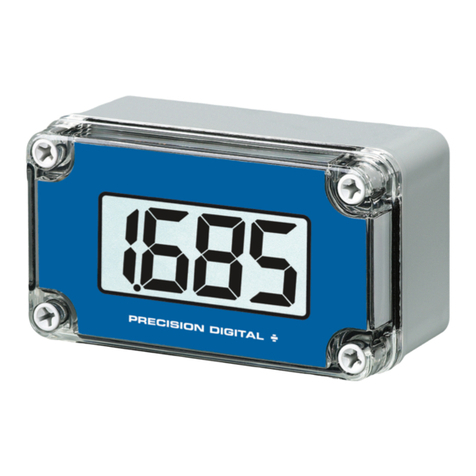
Model Description
PD686* Loop-Powered Meter
in NEMA 4X Enclosure
PDA6844** Panel Mounting Kit
PDA6845 2″Pipe Mounting Kit
*Quick Shipment item, shipped within 2 working days
**Panel Mounting Kit does not provide NEMA 4X seal to panel
ORDERING INFORMATION
MODEL PD686 31/2DIGIT 1″LCD NEMA 4X
1
Volt
Drop!
ACTUAL SIZE
•1″High Display
• Operates From -40 to 85°C
Specifications
APPROVAL:
FM Approved and CSA Certified
as intrinsically safe
with entity, for use in Class I, II, III, Division 1, Groups A, B, C, D, E,
F, G; T-codes: FMRC = T3A, CSA = T4; hazardous locations. Nonin-
cendive for use in Class I, II, III, Division 2, Groups A, B, C, D, F, G.
MAX. ENTITY PARAMETERS: Vmax= 30 V, Imax = 175 mA,
Ci= 0, Li= 0
ENCLOSURE: Impact-resistant glass filled polycarbonate body;
impact resistant clear polycarbonate cover; NEMA & CSA 4X, IEC
529, IP67, 1/2″conduit hole provided at base. May be provided on
back for panel mounting applications, call factory for details.
DISPLAY: Sharp, large 1.0″(25.4 mm) high LCD, ±1999
INPUT: 4-20 mA
CALIBRATION: 2 Step; non-interacting zero and span
CALIBRATION RANGE: 4 mA input: -1000 to
+1000; 20 mA
between 20 and 2000 counts > 4 mA display
ACCURACY: ±0.1% of span, ±1 count
CONVERSION RATE: 2.5 Conversions/second
MAXIMUM INPUT CURRENT: 30 mADC
MAXIMUM VOLTAGE DROP: 1 V at 20 mA
CONNECTIONS: Screw terminal block
OPERATING TEMPERATURE RANGE: -40 to 85°C
(-40 to 185°F); -40 to 40°C (-40 to 104°F) for Canadian installations
WARRANTY: 1 year parts and labor.
EXTENDED WARRANTY: May be extended an additional 12
months by returning the Product Registration Form within 2 months
from date of purchase. Go to www.predig.com for online registration.
www.predig.com
31/2DIGIT NEMA 4X LOOP-POWERED METER
PRECISION DIGITAL CORPORATION
CORPORATE HEADQUARTERS
19 Strathmore Road • Natick MA • 01760 • USA • Tel: (800) 343-1001 • Fax: (317) 216-1277
NOTE 1: If any of the following operations is performed in
the hazardous area, all appropriate hazardous area
procedures must be followed.
NOTE 2: To prevent damage to electronic components
caused by electrostatic discharge, a grounding strap should
be worn when servicing the display.
SETUP
The only tools needed for calibration are a calibrated current source and a
screwdriver.
CALIBRATION CONNECTIONS
To access the input terminals it is necessary to remove the enclosure cover
and the Display PCB. This is done by loosening the four screws on the
enclosure cover and removing the cover. Completely loosen the left screw
that holds the Display PCB to the enclosure and loosen the right screw
about four turns so the Display PCB remains secure to the enclosure.
Rotate the Display PCB 90° to gain access to the Input Signal PCB. Next,
connect a calibrated current source per Figure 1.
DECIMAL POINT SELECTION
The decimal point jumper array is located in the lower right corner of the
Display PCB next to the display. It is labeled DP1, DP2, DP3. Place a
jumper over both pins of DP1 for a display of 199.9, DP2 for 19.99, or
DP3 for 1.999.
CALIBRATION
LO and HI calibration controls are located to the left of the display
(see Figure 1). Apply a signal equal to 4 mA and adjust the LO control to
display the desired reading. Apply a signal between 16 and 20 mA and
adjust the HI control to display the desired reading. Complete the
calibration procedure by making any minor adjustments to the LO and HI
controls.
INSTALLATION
Installation of the meter involves removing the Display PCB from its
enclosure and connecting a 1/2″conduit fitting to the hole provided. Refer
to PD686 FM Approved & CSA Certified Loop-Powered Intrinsic Safety
Barrier Connections Diagrams for further details. Wall mounting holes are
located in each corner of the enclosure (see Figure 4).
LOOP CONNECTIONS
Disconnect power to the loop and install the meter as illustrated in Figure
2 and the PD686 FM Approved & CSA Certified Loop-Powered Intrinsic
Safety Barrier Connections Diagrams that are supplied with the instru-
ment. Replace the enclosure cover.
REMOVING THE DISPLAY PCB FROM ITS ENCLOSURE
Remove the enclosure cover and Display PCB as described in
“Calibration Connection” above. The Display PCB and Input Signal PCB
are connected together with one black and one red wire. The wires are
soldered to the Display PCB and connected to a screw terminal connector
on the Input Signal PCB. Disconnect the black and red signal wires from
the screw terminal connector and lift Display PCB from enclosure. Care
should be taken to avoid static electricity from damaging the electronic
circuitry.
REMOVING THE DISPLAY PCB FROM THE LOOP
Disconnect power to the loop prior to removing the Display PCB from its
enclosure. When removing the Display PCB care should be taken to avoid
static electricity damaging the electronic circuitry. Remove the enclosure
cover and Display PCB as described in the previous paragraph. To restore
the loop, connect LOOP JUMPER (see Figure 1) over both pins. Replace
cover and restore power to the loop. The loop will flow through LOOP
JUMPER. When the instrument is put back in service the push-on jumper
must be removed from LOOP JUMPER pins, save jumper by connecting
over one pin only.
SERVICING THE DISPLAY PCB OUTSIDE THE LOOP
Two modes of input signal allow the user to remove the Display PCB for
service without interrupting the loop as indicated above and operate the
Display PCB at another location. The loop remains connected to the Input
Signal PCB while the Display PCB is absent for service. The user may
operate the Display PCB at another location by connecting a signal to
“S+” & “S-” wires on the Display PCB.
Refer to Figure 3.
LIM686 Rev A 05/00

LO CALIBRATION CONTROL
HI CALIBRATION CONTROL
BALANCE CONTROL
(factory adjust only)
DISPLAY PCB COMPONENT SIDE
(may be removed for bench calibration)
S-
S-
S-
S+
S+
S+
BLACK
RED
LOOP JUMPER
CALIBRATED
CURRENT SOURCE
INPUT SIGNAL PCB
(mounted to base of enclosure)
NO CONNECTION
+-
DP1
DP2
DP3
Figure 1
Calibrator Connected to
Input Signal PCB
INPUT SIGNAL PCB
NO CONNECTIONS
LOOP JUMPER
(remove when Display PCB is connected)
TRANSMITTER
HAZARDOUS AREA NON-HAZARDOUS AREA
POWER
SUPPLY
++
-
-
4-20mA
S+ S+S- S-
Field wiring is
made to the
Input Signal PCB
which is mounted
to the base of
the enclosure.
Figure 2
Control loop Connected
to Input Signal PCB
S+ S-
DISPLAY PCB
COMPONENT SIDE
CALIBRATED
CURRENT SOURCE
DP1
DP2
DP3
Figure 3
The Display PCB may be removed from the
enclosure for bench calibration. Disconnect power
to loop prior to opening the case when operating
in hazardous areas. Install Loop Jumper on Input
Signal PCB to maintain loop.
Calibrator Connected to Display PCB
END VIEW
Wall
Mounting
Holes
Beneath
Cover
Screws
E
F
TOP VIEW
D
AC
B
Figure 4
Dimensions and Wall Mounting Information
Note: To maintain hazardous area location protection, the input signal must always be connected to the Input Signal PCB, and not directly to the Display PCB.
A: 3.15″(80 mm) C: 2.36″(60 mm) E: 2.56″(65 mm)
B: 5.51″(140 mm) D: 4.72″(120 mm) F: 0.79″(20 mm)
Weight: 12 oz (340 g)

Other PRECISION DIGITAL Measuring Instrument manuals

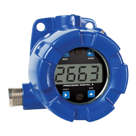
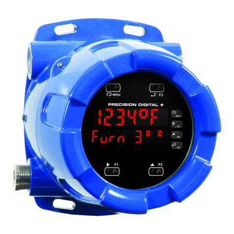
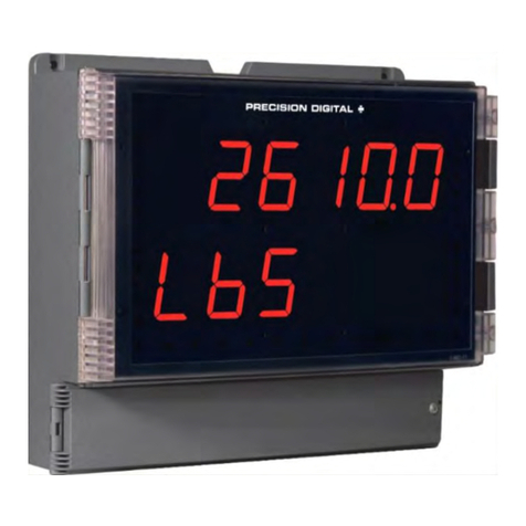
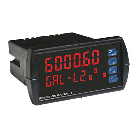
PRECISION DIGITAL Helios PD2-6200 User manual
PRECISION DIGITAL

PRECISION DIGITAL Helios PD2-6200 User manual

PRECISION DIGITAL pd663 User manual

PRECISION DIGITAL

PRECISION DIGITAL pd663 User manual

PRECISION DIGITAL Loop Leader PD683 User manual

PRECISION DIGITAL

PRECISION DIGITAL Loop Leader PD683 User manual

PRECISION DIGITAL ProtEX-MAX PD8-7000 User manual

PRECISION DIGITAL

PRECISION DIGITAL ProtEX-MAX PD8-7000 User manual

PRECISION DIGITAL PD6701 User manual

PRECISION DIGITAL

PRECISION DIGITAL PD6701 User manual

PRECISION DIGITAL pd663 User manual

PRECISION DIGITAL

PRECISION DIGITAL pd663 User manual

PRECISION DIGITAL Helios PD2-6100 User manual

PRECISION DIGITAL

PRECISION DIGITAL Helios PD2-6100 User manual

PRECISION DIGITAL ProVu Series User manual

PRECISION DIGITAL

PRECISION DIGITAL ProVu Series User manual

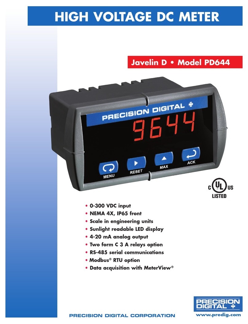
PRECISION DIGITAL Javelin D PD644 User manual

PRECISION DIGITAL

PRECISION DIGITAL Javelin D PD644 User manual

PRECISION DIGITAL ProVu PD7000 User manual

PRECISION DIGITAL

PRECISION DIGITAL ProVu PD7000 User manual

PRECISION DIGITAL ProVu Series User manual

PRECISION DIGITAL

PRECISION DIGITAL ProVu Series User manual

PRECISION DIGITAL ProtEX-MAX PD8-6001 Series User manual

PRECISION DIGITAL

PRECISION DIGITAL ProtEX-MAX PD8-6001 Series User manual

PRECISION DIGITAL PD6800 User manual

PRECISION DIGITAL

PRECISION DIGITAL PD6800 User manual

PRECISION DIGITAL PD8-7000 Series User manual

PRECISION DIGITAL

PRECISION DIGITAL PD8-7000 Series User manual

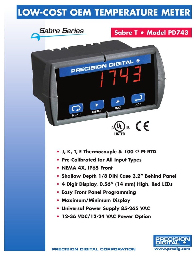
PRECISION DIGITAL SABRE T PD743 User manual

PRECISION DIGITAL

PRECISION DIGITAL SABRE T PD743 User manual

PRECISION DIGITAL SABRE T PD743 User manual

PRECISION DIGITAL

PRECISION DIGITAL SABRE T PD743 User manual

PRECISION DIGITAL PD685 User manual

PRECISION DIGITAL

PRECISION DIGITAL PD685 User manual

PRECISION DIGITAL pd6300 User manual

PRECISION DIGITAL

PRECISION DIGITAL pd6300 User manual

PRECISION DIGITAL PD6060 User manual

PRECISION DIGITAL

PRECISION DIGITAL PD6060 User manual

PRECISION DIGITAL Trident PD765 User manual

PRECISION DIGITAL

PRECISION DIGITAL Trident PD765 User manual

PRECISION DIGITAL ProVu Series User manual

PRECISION DIGITAL

PRECISION DIGITAL ProVu Series User manual

PRECISION DIGITAL PD677 User manual

PRECISION DIGITAL

PRECISION DIGITAL PD677 User manual

PRECISION DIGITAL PD755 User manual

PRECISION DIGITAL

PRECISION DIGITAL PD755 User manual

PRECISION DIGITAL PD6060 User manual

PRECISION DIGITAL

PRECISION DIGITAL PD6060 User manual

Popular Measuring Instrument manuals by other brands

Chatillon DFS II-R-ND user manual

Chatillon

Chatillon DFS II-R-ND user manual

janitza UMG 96-PQ-L installation manual

janitza

janitza UMG 96-PQ-L installation manual

Sony PWS-100TD1 Operation manual

Sony

Sony PWS-100TD1 Operation manual

Sensor ThermCondSys 5500 Operator's manual

Sensor

Sensor ThermCondSys 5500 Operator's manual

Dektak XT User instructions

Dektak

Dektak XT User instructions

Nivetec PCM F instruction manual

Nivetec

Nivetec PCM F instruction manual

SPECTRO Inc. M90301 Operation user's manual

SPECTRO Inc.

SPECTRO Inc. M90301 Operation user's manual

Saci MTA36 user manual

Saci

Saci MTA36 user manual

Trace2O METALYSER HM1000 instruction manual

Trace2O

Trace2O METALYSER HM1000 instruction manual

KRAL BEM 300 Series operating instructions

KRAL

KRAL BEM 300 Series operating instructions

Dytran 3224C operating guide

Dytran

Dytran 3224C operating guide

General MM7 user manual

General

General MM7 user manual

Watts Dormont FloPro-MD Instructions for installing

Watts

Watts Dormont FloPro-MD Instructions for installing

Hanna Instruments HI 98140 manual

Hanna Instruments

Hanna Instruments HI 98140 manual

FMC Technologies INVALCO 64908265 Installation & operation manual

FMC Technologies

FMC Technologies INVALCO 64908265 Installation & operation manual

Drawell DU-8800DS Series user manual

Drawell

Drawell DU-8800DS Series user manual

Velleman DVM1300 user manual

Velleman

Velleman DVM1300 user manual

Sylvac S-Mike PRO instruction manual

Sylvac

Sylvac S-Mike PRO instruction manual

manuals.online logo
manuals.online logoBrands
  • About & Mission
  • Contact us
  • Privacy Policy
  • Terms and Conditions

Copyright 2025 Manuals.Online. All Rights Reserved.