Precision Planting 20/20 SeedSense Manual

955725_4 3/15/22
Operator’s Guide — Air Seeders
For Gen3 20|20 Displays

955725_4 2
Contents
20|20 Monitor Overiew ....................................................................................................................5
Cab Installation.................................................................................................................................8
Powering the 20|20 On and Off......................................................................................................10
Cab Control Module [CCM] ..........................................................................................................11
Home Screen Overview..................................................................................................................12
Controlling the Map .................................................................................................................13
Dashboard Mini Chart ..............................................................................................................15
Individual Row Details.............................................................................................................16
Notification Center ...................................................................................................................17
Summary Information ..............................................................................................................18
Connectivity .............................................................................................................................19
Speed & GPS............................................................................................................................19
Customizing the Home Screen .................................................................................................21
Setup Button ...................................................................................................................................24
Fields ........................................................................................................................................27
Products (Crops).......................................................................................................................33
Alerts ........................................................................................................................................33
Equipment Menu ............................................................................................................................36
Tractor Equipment Setup..........................................................................................................37

955725_4 3
Air Seeder Equipment Setup ....................................................................................................40
Air Seeder Cart Equipment Setup ............................................................................................44
Save/Load.................................................................................................................................45
Systems Menu ................................................................................................................................46
Systems Setup...........................................................................................................................46
Bus Device Setup Examples.....................................................................................................49
Tower Style Seeder...................................................................................................................49
CCS/Drill Style Example .........................................................................................................51
Systems – Down Force.............................................................................................................54
Systems - Granular Products ....................................................................................................57
BXM Setup Example................................................................................................................60
Diagnose .........................................................................................................................................61
Calibration ......................................................................................................................................64
Settings ...........................................................................................................................................65
Overview ..................................................................................................................................65
Software Update .......................................................................................................................65
20|20 Cloud ..............................................................................................................................66
Data...........................................................................................................................................66
Export Data...............................................................................................................................66
Import Data...............................................................................................................................67

955725_4 4
Delete........................................................................................................................................68
Wi-Fi.........................................................................................................................................69
General .....................................................................................................................................69
About ........................................................................................................................................69
Appendix Index ..............................................................................................................................70
Appendix A — Understanding the Home Screen Metrics .......................................................71
Appendix B...............................................................................................................................74
Appendix C...............................................................................................................................76
Appendix D ..............................................................................................................................77
Appendix E...............................................................................................................................78

955725_4 5
20|20 Monitor Overiew
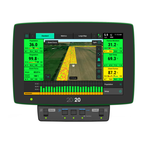
The Precision Planting 20|20 display is a high-definition, easy-to-use monitoring and control
system for planting, seeding, harvesting, and liquid application. Its high definition mapping
features and metrics on single and dual displays allow you to see exactly what is going on in your
fields. Navigate the easy-to-use touch screen for implement and system setup, health checks,
diagnostics, and other helpful information. The 20|20 display provides complete monitoring,
control, and diagnostics for all of Precision Planting’s SRM-based control products for seed and
liquid application, down force control, and in-field sensing in addition to basic planter and
combine monitoring.
The 20|20 has complete control, monitoring, and diagnostics for: vDrive, DeltaForce, SpeedTube,
SmartFirmer, vDrive Insecticide, vApplyHD, FlowSense, vSet Select, mSet, SeederForce, Smart
Connector, and YieldSense.
Software Updates
Precision Planting will continue to update and improve the 20|20. Software updates are free of
charge and can be downloaded from www.2020.ag and installed on the display with a USB drive.

955725_4 6
20|20 Hardware Overview
Either one or two displays can be connected to the Display Base Module at any time. One of
these two displays can be an iPad running the Climate Corporation FieldView Cab app. Displays
can be mounted in any location within the cab.
Display Base Module [DBM]
The Power over Ethernet [PoE] ports requires a Shielded Twisted Pair [STP] Ethernet Cable to
connect to a display. If only one display is being used, use either port. Both ports will be used if
connecting to two displays or one display and a FieldView Module [FVM]. The order by which
two displays or a single display and FVM are plugged in does not matter.

955725_4 7
Indicator Light Overview
Color Display Base Module Display FieldView Module
Green Good Connectivity Good Connectivity Good Connectivity
White Initializing N/A Downloading Software
Blinking White Firmware Update in
Process
N/A N/A
Yellow No Connection between
Display and DBM
Initializing Initializing
Blinking
Yellow
Software Update in
Process
Software Update in
Process
Software Update In
Progress
Blue CCM Connectivity is
Missing
N/A Nothing Connected
Purple Need to Power Cycle
System
N/A FieldView Not Connected
Red N/A Powering On Powering Up
Blinking Red Failure - Call Precision
Support
N/A N/A

955725_4 8
Cab Installation
Step 1:
Mounting locations will vary from tractor to tractor.
Mount the display or both displays for optimal
visibility and interaction for the operator. There are
several mounting options offered by Precision
Planting available for the display. The diagram
depicts the display with a RAM mount.
Step 2:
The Display Base Module [DBM] can be located in
any convenient area of the cab. Ensure the DBM will
not move around when operating the tractor. Plug one
end of the provided Ethernet cord into either port on
the front of the DBM and the other end into the back
of the display. If using two displays connect the
second display with the provided Ethernet cable to the
other open port on the DBM.

955725_4 9
Step 3:
Connect the 725150 Power Harness to the DBM into
the 4-pin Deutsch Connector on the DBM and then to
the power source in the tractor cab. A three pin round
convenience port connector is provided to plug
directly into a standard convenience port. Various
adapters are available to connect to different types of
power ports.
Step 4:
Connect an Implement CAN Harness into the 12-pin
Deutsch Connector on the DBM. Route the remaining
length of the cable through the cab harness port in the
back window. There will be two CAN connections on
the harness, CAN A (black connector) and CAN B
(brown connector). If a PDM is installed, CAN A
must be used and routed to the PDM. If no PDM is
installed, (i. e. Smart Connector only system) then
CAN B must be used.
Note: The 725935 Sensor CAN harness will only
have a CAN B connection present.

955725_4 10
Step 5:
Connect the 725155 Speed Harness to the 8-pin
Deutsch connector on the DBM. This will provide
you with two 4-pin round connections. The male pin
connector will connect to the GPS adapter, while the
female pin connector will connect to the Radar
adapter.
Note: If this system is being used for Sensing only
with a 725939 5Hz GPS Hockey Puck, the 725155
adapter is not necessary. The 725939 harness will
plug directly into the 8–pin Deutsch connector on the
DBM.
Powering the 20|20 On and Off
The monitor must have 12 volts of both switched and constant power. With the power harness
connected to the DBM and power supply, turn the key on the tractor to the On or Run position.
Switch the power button on the DBM to the On position.
To power the system off, either switch the power button on the DBM to the Off position or key
the tractor/combine off.
User License Agreement
Once the 20|20 has booted up, read and agree to
the User License Agreement to use the display.
This will occur on first boot up and when updates
are required for the agreement.
Note: If this system is being set up for a third
party, the agreement should be reset to appear on
next power up for the end user to agree to the
document. This can be done under Advanced
Display settings. Refer to the Display section of
this manual for more details.
Note: This will only appear on 2019.1 and newer
software.

955725_4 11
Cab Control Module [CCM]
The CCM is installed below the display. If two displays are being utilized only one CCM should
be installed (it does not matter which display it is connected to). All planter control products
being run through the 20|20 require a CCM to be installed as it has a Master Plant switch and
swath control features.
The CCM configuration must be set to Present on the 20|20 display on the User Preference screen
(Setup>Settings>User Preferences).
The switch on the left hand side is the Master Plant switch. For all control products to function
the Master Plant switch must be in the up position. If it is in the down position, all control
products will immediately be disabled.
The three switches in the middle are swath section switches. Toggle these to the down position to
swath off a rate section. If all rows are assigned to the same rate section the planter will be
divided into the three parts with each toggle switch controlling swath for one third of the planter.
If these switches are in the down position, the rows assigned to the switch will be shut off.
Assign rows to rate sections in the vDrive/vSet Select setup screens.
The outside two switches in the middle are also used to auto load the meters. Raise these two
switches up together for one second to load the meters. Meters will spin and dispense some seed
as seed is loaded to the disk. This allows seed to immediately be dispensed from the meter when
beginning to plant.
To continue to spin the meters, lift and hold these two switches. Meters will continue to spin as
long as they are held up.
The switch on the right side is the Master Swath switch. If this switch is in the down position, all
rows will immediately be swathed off.

955725_4 12
Home Screen Overview
The Home Screen displays seeding information in an easy to read, easy to navigate format. This
information is presented as both metrics and high definition maps. There are three different home
screen configurations that can be quickly selected to change the layout of the home screen. All
three screens can be customized with different types of measurements, button sizes, map sizes,
control buttons, and minichart. When upgrading from 2019.1.4 software, the only default screen
setup will be the Large Map.
Maps
The 20|20 displays high definition maps while
operating. Different map types can be selected
and viewed during the planting process.

955725_4 13
Selecting the Map Type name (e.g. Coverage) at the top of the map will display the Map Layer
Selection screen. All map types are listed on this page (the systems installed and configured will
determine which map types will build a map). Map types are categorized by General, Air Seeder,
and Seed. For more information on what each map type is mapping see Appendix B.
Controlling the Map
The map will default to displaying the tractor/
seeder in the center of the screen at a preset zoom
level. There are control buttons located around
the map to adjust settings.
To split the map viewing area into two maps at the same time press “Split” in the top right hand
corner of the map screen. When viewing two maps simultaneous, any adjustments done to one
map (other than adjusting the legend) are also applied to the other map. For example, zooming in
on one map will apply the same zoom to the other map.
To exit the split map view, press “Full” on either map type to view only that map.
Change the map orientation by pressing the compass button. Switch between two orientation
modes:
• North Facing – The top of the map is always pointed towards north. The tractor icon will move around
the screen in different directions. This is the default orientation mode. Indicated by the red compass
arrow always pointing towards the top of the screen.
• Implement Facing – The implement icon is always pointed towards the top of the screen and the map
itself moves around the implement. This is indicated by the red compass arrow moving to always
show which direction north is.

955725_4 14
• A third way to change the map orientation is to place two fingers on the map and rotate the map.
Rotating the map in this style will lock the map into the orientation that it was rotated to. To switch
back to North Facing press the compass button. Press it a second time to switch to Implement Facing.
Zooms to a view where the entire field is displayed.
Pressing this button will cause the tractor/planter icon to stay centered in the screen. Additionally,
the zoom level will be reset and zoomed in on the tractor icon.
The Perspective View button will toggle the map view angle from 0, 65, and 75 degrees.
Note: The Perspective View button can only be used once WiFi and background imagery have
been enabled. Refer to the Connectivity and Display sections of this manual for further details.
There are two ways to adjust the zoom level of the map.
1. Use the Zoom In (+) and Out (-) buttons to change the zoom level of the map.
2. Use the standard two finger pinch-in & pinch-out gestures.
Legends for each map can be toggled on by pressing the “On” button in the lower left hand
corner of the map screen.
Toggle Legends off by pressing the “Off” button.
Most legends can be edited. There are two ways to edit legends:

955725_4 15
1. Hold a finger on the legend and slide it up and down to adjust the high and low ends of the legend.
2. Tap on the legend to adjust the High & Low values, number of steps, and use the auto adjust feature.
Note: If a small map has been added to the home screen, none of the control buttons as described above
will be available.
General Mapping Principles
• All maps except for SRI (2 Hz) are mapped at 5Hz, meaning there are 5 data points mapped
for each second of time.
• Maps are mapped on a row by row basis.
• A dark line will be mapped on either side of the planter to distinguish planter passes.
• If the planter appears to be mapping incorrectly, ensure that the planter setup is correct.
• Rows that are inactive or are not collecting information on a row (for example, a row does
not have load cell installed) will not map.
• Map types can be changed at any time by selecting a different type.
• Some map types require specific Precision Planting products to be installed on the planter to
generate the information necessary to create a map.
• If the map has moved away from the tractor/seeder location, a white arrow will appear on the
edge of the map pointing to the direction the tractor/seeder is in.
Dashboard Mini Chart
The DashBoard Mini Chart is located at the bottom of the Standard and Metric Home Screens by
default. The Mini Chart shows a bar chart for one of the measurements of the 20|20 for each row.
Rows that exceed alarm values will turn yellow while rows that exceed alert values will turn red.
Alarm and Alert values can be set in the Alerts menu as described in the Alerts Menu section
below.
Below the bar chart, the active hybrids are displayed. If multiple hybrids are active, the hybrid
name and associated color will alternate among the active hybrids every five seconds. Any row
marked in yellow instead of a hybrid color indicates a row that is currently Swathed Off.
The metric type being displayed on the Mini Chart is located over the “Setup” button. To change
the type of metric, select “Magnitude” (or the metric type displayed) above the Setup button. The
same screen can also be accessed by selecting any of the metric boxes on the home screen or
touching directly on the DashBoard Mini Chart itself.

955725_4 16
On the selection page a larger Row by Row chart will be displayed. On the Navigation Pane on
the right hand side of the screen, select a different metric type to be displayed. Additional metrics
are available if you use a finger to scroll the Navigation Pane downward. Once a different metric
has been selected, press “Home” to go back to the home page. The Mini Chart will now display
the new metric.
Additionally, the Mini Chart can be set to auto
scroll through different metrics. On the selection
page at the top of the Navigation Pane select the
“DMC Auto Scroll” button.
When Auto Scroll is “Enabled”, select the speed
at which the Mini Chart will scroll through
different metrics. Finally, select the metrics/
charts that will be displayed on the home screen
via the Auto Scroll.
Individual Row Details
Detailed information for each Air Seeder row can also be viewed. Access the Row Details screen
by either selecting a metric box on the home screen, touching the Dashboard Mini Chart, or
selecting the metric type that is being displayed on the mini chart. Select “Air Seeder Row
Details” on the right side of the screen. Row Details shows available metrics displayed in a graph
over the past 30 seconds of time. See example below.
The buttons showing row numbers at the bottom of the screen allow the operator to navigate to
other rows.

955725_4 17
Notification Center
The Notification Center is designed to alert the
operator of issues. The Notification Center button
on the home page will give a number indicating
the number of Event Codes that have taken place
since the last reset. Press the button to display all
event codes and a description of the issue.
Select an event code to view additional details about the event code and recommendations for
fixing the issue.
Press “Dismiss All Notifications” to clear out all event codes in the Notification Center. Events
will still be stored in the Event Log.
The “Event Log” button will display a list of all
notifications from the entire system with the
newest at the top. This list is permanent so that
event codes can be referenced when needed.
Select individual event codes to view additional
details and recommendations for fixing the issue.

955725_4 18
Summary Information
Summary information for the active field can be
found by pressing any of the different acre
counters on the home screen or the Field
Summary button under Field Setup (Setup —
Fields). When an acre counter is selected, the
“Counter Details” page will be selected. On this
page summary information will be provided for
acres and seeds planted. Additionally, Liquids
and Insecticides will be displayed with the
number of acres planted and amount used for
each type. At the bottom of the page there are
two acre counters (A & B). These acre counters
do not reset when a different field is made active.
The operator has to press the reset button for
these to reset back to 0.
On the navigation menu on the right side of the screen there are two additional summary pages:
Seeding Down Force Summary and Liquid Down Force Summary. Both the Seeding and Liquid
Down Force summary pages can be displayed for the entire field or for the last pass through the
field. Toggle between these modes at the right side of the page.
Seeder wide averages are available at the bottom of the screen. Colors for each metric will
change according to the limit adjustments configured in the Alerts menu (Setup – Alerts – Seed
or Air Seeder).
Down Force Summary displays row by row
information for average Down Force value (as
determined by the load cell), Margin, Ground
Contact, and Ride Quality for each individual
row. These values are averages for the entire field
or the last pass through the field for each
individual row. Seeder wide averages are
available at the bottom of the screen.

955725_4 19
Connectivity
Speed & GPS
Speed
The top right hand corner of the home screen displays the current speed of the tractor. The bars
under the speed source icon indicate signal strength. The icon itself will be white if the speed
source state is good. It will turn yellow if communication is lost momentarily, there are errors in
the signal, or the GPS fix is lost. The icon will turn red if the speed source becomes unusable.
There are three different icons that can be
displayed:
1. GPS Receiver icon – indicates the speed
source is coming from the GPS system.
2. Tractor/Radar icon – indicates the speed
source is coming from the Radar system.
3. A capital R inside of a box – indicates the
tractor is moving in Reverse.
Note: In 2022.10.0 software, pressing on the Speed button in the top right hand corner will NOT bring up
the GPS Communications Details page.
To access the GPS Communication Page, navigate to Setup > Diagnose > Tractor > GPS.
This page displays information about the GPS information that the 20|20 is receiving. For best
GPS results:
• Set the Baud Rate to 19200 or 38400 in the system outputting the GPS.
• The communication Quality should be as close to 100% as possible.
• There should be at least three satellites within view
• The HDOP should be between 0 – 2.
• Set NMEA messages GGA, RMC (or ZDA), and VTG at 5 Hz in the system outputting the GPS..
(Additional NMEA messages may degrade the GPS information due to too much information being
received).

955725_4 20
GPS Communication
“Reconnect to GPS Receiver” button is located in
the bottom left of this page. Press this button to
force the system to try to reacquire the GPS
signal.
GPS Nudge and Corrections
The GPS Corrections page can be used to
configure how the system handles the GPS
signal.
Navigate to Setup > Equipment > Edit Tractor >
GPS Settings
Bad GPS Correction — This can be changed between Calculated and GPS speed. Use
Calculated for lower grade GPS systems.
Heading Mode — This can be changed between Calculated and GPS. Use Calculated for
lower grade GPS systems.
Correction Level — This setting can be changed from Normal to High. High correction
level will raise the minimum GPS quality percentage for mapping to occur.
Primary Packet — This setting will allow for the user to switch between GGA and RMC
for the primary NMEA packet.
Primary Speed Source —This setting will allow for the user to switch between GPS and
Radar as the primary speed source.
Quick Start Delay —This setting will allow the user to set the amount of time for the Quick
Start Delay function.
Note: Do not change any of the GPS correction settings unless instructed to do so by a Dealer or
Product Support.
GPS Nudge
GPS nudge can be used to move the map data in situations where GPS shift has occurred. Use the
‘+1’ buttons to nudge the map in that direction.
Other manuals for 20/20 SeedSense
3
Table of contents
Other Precision Planting Control System manuals
Popular Control System manuals by other brands
Norac
Norac UC5 Topcon X30 installation manual

Eaton
Eaton COOPER POWER SERIES Installation and operation instructions
Distech Controls
Distech Controls DA-020S Series Hardware installation guide
MKS
MKS 49 Series User manual & installation guide
Neets
Neets echo plus installation manual
Bosch
Bosch Rexroth IndraDrive Mi KCU02 instruction manual
