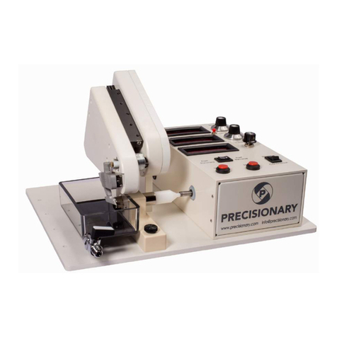
Precisionary Compresstome VF-510-0Z User manual

Compresstome® VF-510-0Z User Manual

1
Thank You
Thank you for choosing the Compresstome® VF-510-0Z!
At Precisionary Instruments, we are thrilled to help you get started with your new vibrating
microtome, and we take great pride in quality customer service. Please read the following
manual to help you get started with the Compresstome® VF-510-0Z.
Safety
Note
The information, numerical data, notes and value judgements contained in this
manual represent the current state of scientific knowledge and state-of-the-art
technology. We aim to update the present manual regularly according to the latest
technical developments. Please contact us or visit our website to find the latest
versions of this user manual.
Contact [email protected] for updated information.
Website: www.precisionary.com
Dangers, warnings, and cautions appear in a box and are marked by the warning
triangle.
Important information for the user, such as disclaimers, appear in a box and
are marked by the information symbol.
Caution! Follow the accompanying documentation.

2
Table of Contents
Thank&You&..........................................................................................................................................................&1!
Safety&...................................................................................................................................................................&1!
Table&of&Contents&............................................................................................................................................&2!
Part%1:%Introduction%.............................................................................................................................%3!
Model&Description&...........................................................................................................................................&3!
Technical&Specifications&...............................................................................................................................&4!
Model&Components&.........................................................................................................................................&5!
Control&Box&Anatomy&.....................................................................................................................................&7!
Accessories&........................................................................................................................................................&8!
Starter&Kit&Components&................................................................................................................................&9!
Part%2:%Setup%.........................................................................................................................................%10!
IMPORTANT!&Transportation&Fixture&Removal&..................................................................................&10!
Mounting&the&Cutting&Blade&to&the&Blade&Holder&................................................................................&11!
Mounting the Cutting Blade to the Magnetic Blade Holder&........................................................&17!
Attaching&the&Gooseneck&Lamp&to&the&Compresstome®&.................................................................&18!
Preparing&Agarose&for&Embedding&..........................................................................................................&20!
Cutting&Parameters&Guideline&..................................................................................................................&22!
Embedding&Tissue&in&Agarose&...................................................................................................................&23!
Part%3:%Operation%................................................................................................................................%25!
Sectioning&with&the&Compresstome®&Tissue&Slicer&...........................................................................&25!
Part%4:%General%Information%...........................................................................................................%27!
General&Cleaning&and&Maintenance&........................................................................................................&27!
Buffer&Tray&Maintenance&and&Cleaning&.................................................................................................&30!
Auto&Zero-Z®&Technology&..........................................................................................................................&31!
Troubleshooting&............................................................................................................................................&32!
Warranty&Information&.................................................................................................................................&34!
Contact&Information&.....................................................................................................................................&34!

3
Part 1: Introduction
Model Description
The VF-510-0Z tissue slicer model is the latest version of our flagship product in the
Compresstome® slicer family. With patented Auto Zero-Z® technology, the VF-510-0Z is
fully automated to section both fixed and live tissues with a thickness range of 4 µm* to
1000 µm and an adjustable precision of 1 µm.
The Compresstome® VF-510-0Z excels at sectioning slices used for:
● Electrophysiology
● Immunohistochemistry
● Organotypic culture slices
● Precision cut tissue slices
● Sectioning of mature or older brain tissues
● And much more!
*Slice thickness minimum depends on tissue sample and organ system.

4
Technical Specifications
Advance Speed
0-20 mm/s, adjustable
Return Speed
20 mm/s
Vibration Frequency
0-45 Hz, adjustable
Vibration Amplitude
2 mm
Z-axis Vibration
~0 µm
Compatible Blades
Stainless Steel, Ceramic, Tungsten Carbide
Cutting Angle
15 degrees (fixed, no need for blade
alignment)
Thickness Adjustment
Automatic
Micrometer Resolution
1 µm
Specimen Tube Diameters
15.5 mm (normal), 20 mm (large)
Maximum Tissue Length
2.5 cm
Minimum Slice Thickness
4 µm*
Cutting Mode
Single or Continuous
Cutting Bath
140 x 60 x 30 mm (maximum 250 mL)
Power Source
For both domestic & international
customers: 100-240 V AC and 50/60 Hz for
each power supply cord.
Only the original power supply unit (power
cord) should be used with the
CompresstomeÒ VF-510-0Z model.
Power Consumption
18 W
Dimension ( L x W x H )
330 x 240 x 190 mm
Weight
5 kg
*Depends on tissue type and organ system.

5
Model Components

6
Figure Number
Compresstome Part
Part Number
Function
1
Vibration Head
--
Blade oscillation
assembly, which
includes a blade
holder and an
oscillation motor
2
Blade Holder
VF-BH-VM-MGNT
Holds and stabilizes
the cutting blade
3
Buffer Tray
VF-BT-510
Holds buffer or
solutions during
sectioning
4
Buffer Tray Valve
VF-BT-PL-BOS
On/off knob to keep
solution in buffer tray
and easily remove
solution when
needed
5
Specimen Tube
VF-SPS-VM-15.5-BOS
VF-SPS-VM-20-BOS
Two different tube
sizes (15.5 mm and
20 mm in diameter)
that hold the
specimen for
sectioning and
embedding tissue in
agarose
6
Tissue Advancement
Plunger (micrometer)
--
Pushes the specimen
tube forward for the
sample to be cut
7
Sliding Control Box
--
Controls for the
cutting speed,
oscillation frequency,
and to set desired
thickness in microns
8
Transportation Fixture
--
Stabilizes vibration
head for safe
transport
All moving and electrical components of the Compresstome® tissue slicer
must be kept dry, in particular the power supply unit.

7
Control Box Anatomy
Figure Number
Control Box Part Name
Control Box Function
1
Slice Thickness Display
Displays the slice thickness your VF-510-0Z
will cut slices to (in µm)
2
Knob that controls Oscillation setting
Control the oscillation frequency of the
blade holder as it cuts
3
Knob that controls Speed setting
Controls how fast the vibration head
travels on its cutting track
4
Start button for sectioning
Will begin sectioning after turning the
machine on (begins vibration head and
blade holder movement)
5
Stop button for sectioning
Stops the vibration head and blade holder
movement along the cutting track upon
being pressed
6
Knob for Slice Thickness setting
Use this knob to adjust and set your
desired slice thickness for sectioning
7a
Continuous Cutting Mode
Will section continuous sections in a row
when in this cutting mode
7b
Single Cutting Mode
Will only section one slice upon pressing
“Start” button
8a
Fast Reverse function
Moves the tissue advancement plunger in
reverse, retreating into the control box.
8b
Fast Forward function
Moves the tissue advancement plunger
forward, towards the specimen tube
plastic plunger

8
Accessories
Figure Number
Compresstome Part
Part Number
Function
1
Chilling Block
VF-VM-CB-15.5-BOS
VF-VM-CB-20-BOS
Rapidly chills agarose in
specimen tube for
sectioning
2a
Specimen Tube:
Plastic Plunger
VF-SPS-VM-15.5-BOS
VF-SPS-VM-20-BOS
Where tissue sample is
glued onto
2b
Specimen Tube:
Metal Tube
Outer metal tube that the
plastic plunger moves
through for the sample
to be cut
3
Acetone Bath for
Blade Holder
VF-VM-AB
Use to clean the blade
holder via acetone soak
4
Allen Wrench for
Blade Holder
VF-BH-VM-AW
Use to remove and
tighten the small screw
on the blade holder when
taking it on/off the
machine
5
Power Cord
VF-VM-PC-BOS
Power cord for the VF-
510-0Z model.!
6
Magnetic Blade
Holder
VF-BH-VM-MGNT
Apply the blade to the
blade holder via magnets
(stainless steel) or glue
(ceramic and tungsten)
7
Buffer Tray
VF-BT-510
Holds the buffer solution
and specimen tubes for
sectioning
8
Plastic Cleanup
Razors
VF-BL-VM-PCR
Use to clean the edges of
the plastic plungers after
sectioning with the
Compresstome®

9
Starter Kit Components
Note: All of our Compresstome® consumables can be ordered online at:
https://precisionary.com/e-store/
Contact us directly at [email protected] and we will send you a quote.
Consumable
Part Number
Quantity
Description
Agarose Tablets
VF-AGT-VM-10
10
Low melting agarose for
embedding tissue.
Blades
VF-BL-VM-SSB
10
Double-edged stainless-steel
blades.
Pipettes
__
2
Plastic, disposable pipettes
included for easy transfer of
agarose into the specimen
tubes for embedding.
Glue
VF-VM-GLUE
1
Used for securing blades to the
blade holder and tissue
specimens to the specimen
tube.
Forceps
VF-VM-FORCEPS
2
Small forceps for easy manual
manipulation of tissue sample.
Petroleum Jelly
VF-VM-PJ
1
Petroleum jelly recommended
for application to the inside of
the tube adapter to help
prevent minor leaks for
Compresstome slicer buffer
trays (0.16 ounces each
packet)
Plastic Cleanup
Razor
VF-BL-VM-PCR
5
Use to clean the edges of the
white plungers after sectioning
with the Compresstome.
Only use Precisionary supplied parts for Compresstome® operation; this
includes only using the chilling block, blade holder, specimen tubes and
buffer tray supplied with your Compresstome® tissue slicer. Do not use
parts supplied from alternate suppliers for use with the Compresstome®.

10
Part 2: Setup
IMPORTANT! Transportation Fixture Removal
Please remove the transportation fixture before your first-time use. This fixture will need
to be securely mounted back to the machine before any future shipment.
Before using the Compresstome® slicer, you MUST remove the thumbscrew
that holds the “transportation fixture” in place on the machine. This piece is
screwed in at the back of the vibrating head and is there to help stabilize the
Compresstome® during shipment. Failure to remove the transportation
stabilization plate may result in damage to the vibrating head.
1. Remove thumbscrew that is
on the right side of the
transportation fixture. You do
not need to remove anything
on the left side (leave as is).
2. After removing the thumbscrew, the
transportation fixture will fall shown
in the picture above. Place the
thumbscrew back into the machine so
that it does not get lost and that you
can reattach the transportation fixture
for any future shipments.

11
Mounting the Cutting Blade to the Blade Holder
Double-edged razor blades, ceramic blades, and tungsten carbide blades are ideal for this
vibrating microtome. The Compresstome® Starter Kit includes either 10 double-edged
razor blades or two ceramic blades to get you up and running with your Compresstome®
purchase. The blades should be cleaned with acetone and ethanol before use.
The sharpness of the blade can directly affect the quality of the slices. As seen in the
table below, we recommend replacing blades periodically according to the razor and
tissue type.
Razor Type
Tissue Type
Replacement Frequency
Double-edged
Standard (brain, lung,
gastrointestinal, skin)
Every 3-5 samples
Fibrous (lymph nodes, liver,
spleen, kidney)
Every 1-2 samples
Ceramic
All
Every 3-4 weeks
Tungsten
All
Every 1-2 weeks
For each double-edged stainless steel blade, cut the blade horizontally to form two
separate blades. You will only need one of the two resulting blades for each use. For
ceramic and tungsten blades, remove one of the blades carefully from the pack.
Blade Type
Blade Picture
Stainless Steel Double-Edged Blades
Ceramic Blade
Tungsten Carbide Blade

12
How to Properly Cut the Double-Edged Blades
Step #
Instruction
Picture
1
Carefully cut the double-edged
blades horizontally:
2
Two separate blades will form:
3
After the stainless-steel blades are cut in half, trim the extra tabs (curled
edges) on the ends of the blades so they don’t stick out beyond the blade
(pictured in step #2). If using a ceramic or tungsten blade, simply remove one
carefully from pack to apply directly to the blade holder.
4
The blades will be ready to use and
will look like this:
Curled'edges'
after'the'blades'
are'cut'in'half
Curled'edges'
after'the'blades'
are'cut'in'half
Exercise caution when handling sharp objects and always remember to
wear gloves and safety goggles while operating the Compresstome®.

13
"#$!%#!&'#()'*+!,#-.%!%/)!0-%%1.2!3*45)!%#!%/)!3*45)!"#*5)'!614!7*-)!
1
To remove the blade holder from the
vibrating head unit, loosen the small
screw on top of the blade holder with the
included Allen wrench.
!
2
Slide the blade holder off the axial bar.
!
3
Remove the old cutting blade.
!
!
!
Always remove the blade holder
BEFORE removing or inserting
the buffer tray.
Dispose of blade safely into a
sharps container.

14
4
Soak the blade holder in the acetone
bath for 5 minutes. Wipe off any
residual glue on the blade holder using a
paper towel. It is critical to ensure all
glue residue is removed before
attaching a new blade.
!
5
Squeeze a small amount of super glue
onto a petri dish or other solid surface.
!
6
Pipette 5 µL of the super glue along the
full length of the blade holder.
!
DISCLAIMER: Please only use
acetone to clean the blade
holder and specimen tube. The
buffer tray is not made of
acetone safe materials.

15
7
Position the cutting blade on the blade
holder. The edge of the blade should
touch the raised lip of the blade holder
(see step #7a).
Make sure the exposed surfaces of the
blade are clean to prevent damage to
tissue.
Press firmly, then allow the glue to dry
for one (1) minute before use.
!
!
!
!
7a
You are ready to use your blade/blade
holder when the cutting blade is
positioned like this:
When applying a ceramic or tungsten
blade, follow the same steps here to
glue the blade and ensure that the top
edge of the blade is aligned against the
raised lip of the blade holder.
!
Do NOT touch blade
edge.
The ceramic and
tungsten blades must be
glued onto the blade
holder.

16
7b
You do NOT want your cutting blade to
be mounted like this:
On the left side, the trimmed, curled
edge is on the raised lip of the blade
holder and the blade is off-centered.
On the right side, you can see how the
blade is off-centered. The curled edge
was also not trimmed on this side.
!
7c
This is another example of how you do
NOT want to mount your cutting blade
to the blade holder:
Notice that the top edge of this blade is
not touching the blade holder edge, and
it is also not centered.
There is also a buildup of glue on the
blade holder, and this should be
cleaned before mounting a new cutting
blade.
!
!

17
Mounting the Cutting Blade to the Magnetic Blade Holder
!
8/)!942.)%1:!;*45)!/#*5)'!:4.!;)!-<)5!$1%/#-%!2*-)!%#!45/)')!%/)!<%41.*)<<=<%))*!;*45)<!#.*+>!8/)!
;)*#$!51'):%1#.<!)?(*41.!/#$!%#!4%%4:/!%/)!<%41.*)<<=<%))*!;*45)<!%#!%/)!942.)%1:!;*45)!/#*5)'>!
@/1*)!%/)!942.)%1:!;*45)!/#*5)'!:4.!<%1**!/#*5!:)'491:!4.5!%-.2<%).!:4';15)!;*45)<A!%/)<)!;*45)<!
$1**!.))5!%#!;)!4((*1)5!614!2*-)!1.!%/)!4;#6)!<%)(<!#.!(42)<!BC=BDA!%/)+!4')!.#%!942.)%1:>!8#!
:*)4.!%/)!942.)%1:!;*45)!/#*5)'A!<#4E!1.!*1F-15!#6)'.12/%!4.5!5'+!G!:*)4.!'12/%!4H%)'!-<)>!
!
Step&
Instruction&
Photo&
!!!!!
!
!
!
!
B!
!
8/)!942.)%1:!;*45)!/#*5)'!$1**!
/46)!61<1;*)!942.)%<!4*#.2!%/)!
#-%)'!<15)!I*)H%!(/#%#J!#H!%/)!/#*5)'>!!
!
K#:4%)!%/)!1..)'!<15)!#H!%/)!;*45)!
/#*5)'!I'12/%!(/#%#JA!$1%/!%/)!
'41<)5!*1(!4*#.2!%/)!%#(!)52)A!4<!%/1<!
1<!%/)!<15)!#H!%/)!;*45)!/#*5)'!%/)!
;*45)!$1**!;)!4((*1)5!%#>!
!
!
!
!
!
L!
!
!
04')H-**+!')9#6)!4.5!:-%!#.)!#H!%/)!
5#-;*)=)52)5!<%41.*)<<=<%))*!;*45)<!
H#'!+#-'!)?()'19).%!I<))!(42)!BLJA!
4.5!(')(4')!%#!(#<1%1#.!%/)!;*45)!
#.!%#(!#H!%/)!H*4%!<15)!#H!%/)!;*45)!
/#*5)'>!
!
!
!
!
C!
!
!
04')H-**+!(*4:)!%/)!;*45)!#.!%/)!
;*45)!/#*5)'!<#!%/4%!%/)!%#(!)52)!#H!
%/)!;*45)!%#-:/)<!%/)!;#%%#9!)52)!
#H!%/)!'41<)5!;*45)!/#*5)'!*1(>!
!
!
!
!
!
M!
04')H-**+!<*15)!%/)!;*45)!%#$4'5<!
%/)!'12/%!H'#9!%/)!)52)!/4.21.2!#HH!
%/)!;*45)!/#*5)'!%#!:).%)'!%/)!;*45)!
4*#.2!%/)!942.)%<>!!
!
N.:)!+#-'!;*45)!1<!:).%)')5!4.5!
4*12.)5A!+#-!4')!')45+!%#!-<)!+#-'!
.)$!942.)%1:!;*45)!/#*5)'O!
!
!

18
Attaching the Gooseneck Lamp to the Compresstome®
Step&
Instruction&
Picture&
1
To attach the Gooseneck Lamp, you will first
need to attach the Magnet “Puck” and
thumbscrew onto the base of your
Compresstome model.
The photo on the top shows the two pieces
separately, and the photo on the bottom
shows the two components as one (i.e. how
they will be installed on your
Compresstome).
!!!
!
2
To attach the magnet “puck” onto the
Compresstome, first choose which slotted
hole you wish to attach the magnet “puck”;
which will be one of the four slotted holes
shown here.
For example, the second slotted hole from
the top is chosen in this photo. Separate the
two pieces, and place the magnet (the
“puck” part) into the desired slot, as shown
here:
.
3
Next, carefully tilt the Compresstome® on
its “back” so that the bottom is facing you.
**When doing this step, the magnet “puck”
may fall out! Please be sure to either hold
onto the puck as you gently tilt the
Compresstome, or reinsert the puck once
the Compresstome is on its side.
Take the thumbscrew and screw it onto the
end of the magnet puck underside of the
Compresstome.
Once attached, it will look like so:
&

19
4
Now, gently lay the Compresstome upright,
and you are now ready to attach your
Gooseneck Lamp to your Compresstome!
You can see from the two photos that the
magnet “puck” rests on the top of the
Compresstome base, and the thumbscrew
holds the magnet in place from the
underside of the base of the
Compresstome, as shown in the second
photo:
&
&
&
5
The bottom of the Gooseneck Lamp easily
attaches to the top of the magnet “puck”
and so the lamp will stay in place
throughout sectioning!
Once the magnet “puck” is installed onto
your Compresstome® base, you can gently
place your Gooseneck Lamp on top of the
magnet “puck”.
!
!
6
Plug the lamp into a nearby standard outlet,
flip the switch “on”, and angle the
Gooseneck Lamp how you choose for your
experimental needs.
Here are some examples of our favorite
Gooseneck Lamp positions during use:
The Gooseneck Lamp is flexible, there are
many different ways to utilize the
Gooseneck Lamp during use with the
Compresstome!
!
!
Table of contents
Other Precisionary Laboratory Equipment manuals
Precisionary
Precisionary Compresstome VF-310-0Z User manual
Precisionary
Precisionary RF-800 User manual
Precisionary
Precisionary Compresstome VF-210-0Z User manual

Precisionary
Precisionary Compresstome VF-310-0Z User manual
Precisionary
Precisionary RF-1000 User manual
Precisionary
Precisionary CRYOSTAT CF-6100 User manual
Precisionary
Precisionary RF-600 User manual
