Prime Controls LH200 User manual

LH200 Light Leak Detector
Operating Instructions
Revision D
08/11/2017
Prime Controls, Inc.
DESCRIPTION
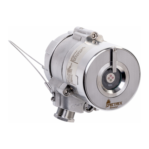
The LH200 light sensor is designed to be a component of a light-based inspection system for finding leaks in
container ends and containers. In addition to the LH200, a complete inspection system requires: a controlling
PLC, a Prime Controls SL100 LED Strobe Lamp, and a reject mechanism. If the test system comprises
multiple lanes, where the flash energy from one lane can cross-couple into another lane, the system may
also require the use of the Prime Controls SQ100 sequencer to stagger the triggering of the individual
sensors.

2
OPERATION
Once set up, the operation of the LH200 involves only three control signals, an ENABLE signal from the PLC
or sequencer to start the test cycle, a STROBE output signal to trigger the flash illuminator, and a RESULT
output signal to report the outcome of the test to the PLC.
In general terms, an inspection cycle comprises the following steps:
1. An enable signal is sent to the LH200 to begin the test cycle.
2. The LH200 takes 128 readings and averages them as a dark reference.
3. The LH200 asserts the STROBE signal to trigger the flash illuminator.
4. The LH200 captures the peak signal sensed during the flash.
5. The LH200 assesses the dark level and peak value and reports a leak if either or both signals
exceed their respective test limits.
The test cycle is described in greater detail later in this document. See TEST CYCLE DETAIL
USER INTERFACE
The LH200 may be connected to a terminal, laptop, or personal computer for user access to configuration
parameters. Set the serial connection parameters to 34800 baud, 8 data bits, 1 stop bit, no parity and no
handshake. When the connection has been established, enter a question mark, “?” to display the command
menu:
Commands:
A– Auto Adjust, 0/1
B– Bias
C– Cal Offset
F– Free Run
D– Dark Limit
G– Gain
S– Spread Limit
L– Leak Limit
R– Reports
V– Version
?– Menu
Note on Parameters:
In most user applications, it will not be necessary to adjust the available parameters. The default values were
determined by testing in a typical, real world installation. However it may be necessary to adjust the Leak
Limit and Dark Limits based on ambient light intrusions and desired leak reject levels.
A- Auto Adjust
The “A” command allows the user to enable and disable the auto adjust feature. “A” has only two values, 0
and 1. Zero disables the auto adjust feature and 1 enables it. The default is 1, enabled.
The auto adjust mechanism monitors the average of the internal bias readings taken during the dark period
of the test cycle and adjusts an internal offset to maintain the dead-band as specified by the “B” setting. This
insures constant sensitivity through a wide range of temperatures. It is recommended to leave this setting
enabled for most installations.

3
The auto adjust setting is recorded in non-volatile memory and is retained through power cycling of the
LH200.
B- Bias
Displays and opens the bias value for change. If the displayed value is to be retained, simply press ENTER
to accept the current value. Otherwise, enter the new value then press ENTER. Acceptable range is 1
through 100. Default is 30. This command cannot be entered when a machine is running (LH200 is receiving
a periodic ENABLE signal).
This value determines the size of the dead-band from complete darkness to a measurable signal. Increasing
this value decreases the sensitivity of the LH200. The smaller the bias value, the more likely extraneous
noise may trigger a leak response from the LH200. In most instances, adjusting the Bias is not necessary.
NOTE: The bias value should only be changed when the sensor is in complete darkness since a change to
the bias value automatically initiates a re-calibration of the LH200. Calibration may also be initiated through
the “C” command.
The bias value is recorded in non-volatile memory and is retained through power cycling of the LH200.
C– Cal Offset
Initiates calibration of the internal offset voltage required to maintain the bias as specified through the “B”
value. The gain setting does not affect this operation. NOTE: For meaningful calibration, the face of the
LH200 must be in complete darkness. This command cannot be entered when a machine is running (LH200
is receiving a periodic ENABLE signal).
D– Dark Limit
Displays and opens the dark limit value for change. If the displayed value is to be retained, simply press
ENTER. Otherwise, enter the new value then press ENTER. Acceptable range is from 1 to 4000. The
default is 30. This parameter determines how much light leakage is allowed after the test cycle has begun
and before the flash has been triggered. If the average of the dark readings during a test cycle exceeds the
dark limit, the report LED is set to amber and the RESULT output is turned off (reject state).
The dark limit is recorded in non-volatile memory and is retained through power cycling of the LH200.
F- Free-Run Mode
The LH200 is set to free-run mode by entry of the “F” command through the serial port. Free-run mode
cannot be entered if the machine is running (LH200 is receiving a periodic ENABLE signal). The operation
of the LH200 in free-run mode is as follows:
1. The ENABLE signal is ignored.
2. A cycle begins immediately after entry of the “F” command. The results of the test are reported on the
RESULT output, on the result LED, and the serial output.
3. The cycle repeats every 100 milliseconds until a character comes in from the serial port. Any character
from the terminal or PC terminates the free-run mode.
Note that in the free-run mode, the results are held on both the LED and the reject output until the next
inspection cycle while in normal press operation, the reject output is unconditionally set to the reject mode
when the enable signal is removed.

4
G– Gain
Displays and opens the gain value for change. If the displayed value is to be retained, simply press ENTER
to accept the current value. Otherwise, enter the new value then press ENTER. Acceptable range is 10
through 100. Default is 100. The gain value specifies the gain as a percentage of maximum sensitivity. 100
is maximum sensitivity, 10 is 10% of maximum sensitivity.
A change in gain affects both the dark reading sensitivity and the peak reading sensitivity.
The gain value is recorded in non-volatile memory and is retained through power cycling of the LH200.
L– Leak Limit
Displays and opens the leak limit value for change. If the displayed value is to be retained, simply press
ENTER. Otherwise, enter the new value then press ENTER. Acceptable range is from 1 to 4000. The
default is 500. If the peak signal that occurs during the flash period exceeds the leak limit, the report LED is
set to red unless the LED is already amber from the reporting of a dark fault. The RESULT output is turned
off (reject state).
If the peak signal does not exceed the leak limit and neither the dark average nor the dark spread exceed
their respective limits, the LED is set to green and the RESULT output is set high.
The leak limit is recorded in non-volatile memory and is retained through power cycling of the LH200.
R– Reports
The “R” command displays the currently enabled reports to be output for display over the serial port. The
value of each enabled parameter is displayed at the end of each test cycle. The parameters display in the
order in which the reports are listed when “R” is entered.
After the enabled reports are listed, the LH200 asks if the user wishes to change the selection of enabled
reports: Change? (Y/N). If “N” is entered, no change is made to the enabled list. If “Y” is entered, the list of
available reports is displayed, one at a time, to allow the user to enable the report (enter “Y”) or disable the
report (enter “N”). A typical scenario might be as follows:
Dark Average (Y/N) Yes
Dark Spread (Y/N) No
Peak Value (Y/N) Yes
Leak Factor (Y/N) No
Temperature (Y/N) No
Result Flags (Y/N) Yes
*(R command entered here)
Enabled Reports:
Dark Average
Peak Value
Result Flags
Change? (Y/N) (N entered here)
*
The selection of reports is recorded in non-volatile memory and is retained through power cycling of the
LH200.

5
The result flags are D, N and L. Their meaning is as follows:
D – the average dark current exceeded the dark limit
N – the dark spread exceeded the spread limit
L – the peak value exceeded the leak limit
S– Spread Limit
Displays and opens the spread limit value for change. If the displayed value is to be retained, simply press
ENTER. Otherwise, enter the new value then press ENTER. Acceptable range is from 1 to 4000. The
default is 500. This parameter determines how much variation in signal is allowed during the dark interval of
the test cycle. If the spread in dark readings during a test cycle exceeds the dark spread, the report LED is
set to amber and the RESULT output is turned off (reject state). For most applications this test has limited
meaning and may be essentially disable by setting the limit to a high value. Its primary usage is for detecting
electrical noise.
V– Version
Displays the controller firmware version number in the form of 1.01 for example.
?– Menu
Displays the command menu as shown at the beginning of this section.

6
TEST CYCLE DETAIL
The inspection cycle comprises the following steps:
1. The LH200 begins the test cycle by awaiting the assertion of the ENABLE signal from the PLC or the
SQ100 (high on gray wire, connector pin 5).
2. Prior to assertion of the ENABLE signal, the test sample is indexed into position between the sensing
face of the LH200 and the illumination device..
3. The PLC then sends the ENABLE signal to the LH200 or SQ100 sequencer. The sequencer generates
individual ENABLE signals for the LH200 units on each lane of the tester or press. The ENABLE signals
are generated 1 millisecond apart to insure that no two lanes flash at the same time.
4. The ENABLE signal passes from the PLC or SQ100 to the LH200 (high on gray wire, connector pin 5)
indicating the end is in position for inspection.
5. The LH200 responds immediately to the ENABLE signal by turning the report LED off then takes 128
consecutive light readings and averages them as a dark reference. The dark reading interval plus delay
lasts 5.25 milliseconds.
6. After the dark readings are taken, the dark level average is tested against the dark limit and the dark
spread is tested against the spread limit. If either limit is exceeded, the amber LED is turned on.
7. The LH200 awaits the end of the 5.25 mS interval then asserts the STROBE signal, activating the flash
(yellow wire, connector pin 4 set high) and captures the peak light resulting from the flash.
8. When the 1 millisecond peak capture interval has expired, the captured peak value is compared to the
leak limit. If the peak value exceeds the limit but the dark average and dark spread are within limits, the
result LED is set to red. If dark average, dark spread and peak are all within limits, the report LED is set
to green. If either the dark level or the spread of the dark level readings exceeds limits, the report LED
remains amber even if the peak value exceeds its limit.
9. The LH200 delays another 3.5 milliseconds then releases the STROBE signal (yellow wire, connector
pin 4 set low) and, if no leak, sets the RESULT output high (white wire, connector pin 1). The delay
insures a quiet power supply in the flash unit until all later lane inspections have been completed.
10. The LH200 controller then sends the results of the inspection to the serial output (pink wire, connector
pin 6, 38400 baud). This is an RS-232 signal that may be connected to the serial port of a terminal or
computer.
11. The LH200 then awaits the release of the ENABLE signal (low on gray wire, connector pin 5). When
released, the RESULT output is set low (white wire, connector pin 1) and the cycle begins again at step
1 above.
See Timing Diagram below.

7
TIMING
TEST ENABLE
READ DARK
STROBE
PEAK CAPTURE
DELAY
NO-LEAK RESULT
LEAK RESULT
5.25 mS
1 millisecond
3.5 mS
CONNECTOR PINOUT
Pin Wire Color Signal Direction
1 White Result Out
2 Brown Power (+24V) In
3 Green Serial Data In In
4 Yellow Strobe Trigger Out
5 Gray Test Cycle Enable In
6 Pink Serial Data Out Out
7 Blue Common --
8 Shield Connect to Common --
RS-232 CONNECTION
The illustration below, defines the wiring requirements for accessing the serial port capabilities of the LH200
using the standard 9 Pin Female D Sub Connector (DB9).
12
3
4
5
6
7
89
M12 PIN 3 (CABLE GEEN)
M12 PIN 6 (CABLE PINK)
M12 PIN 7 (CABLE BLUE)
FEMALE CONNECTOR
FRONT VIEW
M12 MALE
1
7
6
5
4
3
8
2
M12 MALE
1
7
6
5
4
3
8
2

8

9
SIGNAL SPECIFICATIONS
Power (Pin 2) 24V DC +/- 10%
ENABLE (Pin 5) Active high, 15 – 24 Volts.
10K ohms input impedance.
Zener limited at 30 volts.
RESULT (Pin1) Sourcing output, active high.
Off: zero volts.
On: supply voltage less 1 volt.
Output impedance: 200 ohms.
STROBE Trigger (Pin 4) Active high.
Off: zero volts.
On: supply voltage less 1 volt.
Output impedance: 1500 ohms
Serial Transmit (Pin 6) RS-232 levels.
Baud rate: 38400
Serial Receive (Pin 3) RS-232 levels
Baud rate: 38400
LH100 AND LH200 DIFFERENCES
From an installation and operational perspective, the LH100 and LH200 are fully compatible. External
hardware differences are detailed below.
Feature LH100 LH200
Report LED (near connector) Off - no leak Off – after power-up, no testing done
Amber – failure Green – no leak
Amber – high dark level or spread
Red – leak detected with flash
Dark Measurement 4 Samples 128 Samples
Dark Threshold Fixed User settable
Spread Threshold Fixed User settable
Peak Threshold Fixed User settable
System Gain Fixed User settable
System Bias Fixed User settable
Invoke free-run mode Connect signal to common Enter “F” through terminal or laptop
Serial communications Logic level signal RS-232 level signals
Out only, 9600 baud Bidirectional, 38400 baud
Serial output data Fixed: Dark Average, Dark Selectable: Dark Average, Dark Spread
Spread, Peak, and Flags Peak Value, Leak Factor, Temperature
and Flags

10
LIMITATIONS AND EXCLUSION OF WARRANTIES
All goods purchased from PRIME CONTROLS, INC. shall be free from defects in materials, design and workmanship
under normal conditions of use for one year from the date of shipment. THIS WARRANTY IS THE SOLE
WARRANTY AND IS EXPRESSLY IN LIEU OF ALL OTHER WARRANTIES, EXPRESS OR IMPLIED,
INCLUDING BUT NOT LIMITED TO ANY IMPLIED, WARRANTY OF MERCHANTABILITY OF FITNESS
FOR A PARTICULAR PURPOSE. THE LIABILITY OF PRIME CONTROLS TO ANY PURCHASER SHALL BE
LIMITED EXCLUSIVELY TO THE COST OF REPLACEMENT OR REPAIR OF DEFECTIVE PARTS, AND
SHALL NOT INCLUDE LIABILITY FOR ANY DIRECT, CONSEQUENTIAL OR INCIDENTAL DAMAGES
WHATSOEVER, WHETHER FORESEEN OR UNFORESEEN, INCLUDING BUT NOT LIMITED TO LOST
PROFITS, LOST SALES, OR INJURY TO PERSONS OR PROPERTY.
This document is confidential and proprietary. No part of this document may be
disclosed in any manner to a third party without the prior written consent of Prime
Controls, Inc.
This manual suits for next models
1
Table of contents
Other Prime Controls Security Sensor manuals
Prime Controls
Prime Controls DS3410 User manual
Prime Controls
Prime Controls DS1522 User manual

Prime Controls
Prime Controls FLUXIMITY DS71 User manual
Prime Controls
Prime Controls LH200H User manual
Prime Controls
Prime Controls DS600 User manual
Prime Controls
Prime Controls SD220 User manual
Prime Controls
Prime Controls SD230M User manual

Prime Controls
Prime Controls SD220 User manual
Prime Controls
Prime Controls DS1510 User manual
