SETUP
12
INITIAL SETUP
Probe and Gap Assessment
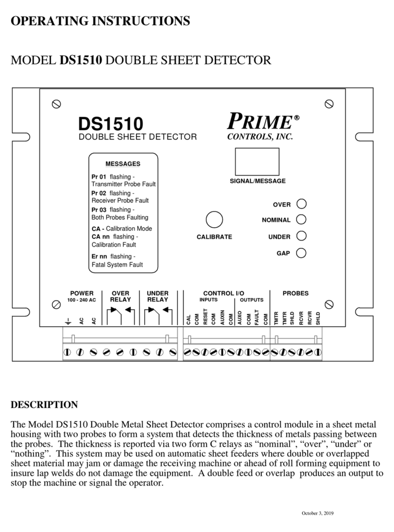
The startup process of the DS1522 commences immediately after power up and includes
several processes which are transparent to the user except for the sequence of characters that
appear on the two digit display.
When the unit first powers up, the probes are analyzed to determine the type or probe attached to
the control unit. While the assessment is in process, the letters Pr flash on and off. When the
type of probe has been established, the probe identifier flashes alternately with Pr for
approximately 3 seconds. The probe identifiers include 15, 70, and 1H. After identifying the
probes, the control module determines which calibration preset is to be used and then displays
alternately SL and the preset number, e.g. SL 01. If the probes are faulty, disconnected, or
cannot be identified, the controller flashes PR 01 indefinitely.
After the probes have been identified and the calibration memory selected and displayed, the
control module begins displaying the signal strength from the receiving probe. If the system
has been newly installed or the relative positions of the probes has been changed, it is
necessary to “calibrate the gap”. With no material between the probes, press and hold the
CALIBRATE GAP pushbutton for three seconds until the letters SU and gAP flash alternately
on the display. The system records the “no material condition” in non-volatile memory. When
the display reverts to displaying signal strength, the gap calibration process is complete. It is
essential that for this assessment there is no material between the probes.
When the operating conditions have been established, the two digit readout displays a numeric
value representing the receiver signal strength.
Gauge Tolerance Adjustment
When the startup sequence has been completed and if the probes are successfully identified, the
system enters gauge mode and displays the receiver signal strength on the two digit display. At
this point the gauging tolerances should be verified and/or set as described below: If more than
one calibration memory is to be used, the tolerances must be adjusted independently for each
stored calibration. The tolerance adjustments may be done any time except when the system is
in calibration mode (displaying “CA”).
1. Press and hold the calibration pushbutton for 3 seconds or until the unit displays “Ut”
(Upper tolerance). Release the pushbutton and observe the setting for the upper tolerance
value. The tolerance displays as a percentage of the single thickness and can be adjusted
from a value of 1 to 99. If the pushbutton is not pressed again within 5 seconds, the display
reverts back to displaying gauge signal strength and the current upper tolerance value is
retained. To change the upper tolerance, tap or hold in the pushbutton as necessary to
adjust the upper tolerance to the desired value. For detection of doubles, 50% is a good
value. Retain and store the displayed value by releasing and not activating the pushbutton
for 5 seconds. The display reverts back to showing signal strength.
2. Press and hold the calibration pushbutton for 4.5 seconds or until the unit displays “Lt”
(Lower tolerance). Release the pushbutton and observe the setting for the lower tolerance
value. The tolerance displays as a percentage of the single thickness and can be adjusted
from a value of 1 to 99. Tap the pushbutton as necessary to adjust the lower tolerance to
the desired value. If gauging for “under” is of no interest, set the lower tolerance to a high
value such as 99%. Retain the displayed value by releasing and not activating the
pushbutton for 5 seconds. The display reverts back to showing signal strength.


