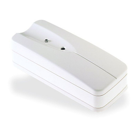
Prime Controls LH200H User manual

LH200H, SL100H End Leak Detection System
Operating Instructions
202867 Revision H
03/13/2023
Prime Controls, Inc.
DESCRIPTION
The LH200H, SL100H End Leak Detection System uses Prime Controls Eclipse Leak Detection
Technology to provide state-of-the-art light-based end leak detection for conversion presses.
The system can operate at up to 1000 ends per minute while detecting holes as small as 0.5µm.

LH200H, SL100H End Leak Detection System
This document is confidential and proprietary. No part of this document may be disclosed in any manner
to a third party without the prior written consent of Prime Controls, Inc.
202867 i Revision H

LH200H, SL100H End Leak Detection System
This document is confidential and proprietary. No part of this document may be disclosed in any manner
to a third party without the prior written consent of Prime Controls, Inc.
202867 ii Revision H
Revision History
Revision
Date
Description
Author
A
2020-08-31
Initial Release
RMC
B
2020-09-10
Document clean up.
RMC
C
2020-12-16
Fixed missing references to drawings.
RMC
D
2021-05-26
Revised drawings 202798, 202866
RMC
E
2021-06-22
Revised with LH200H 2.4 firmware related changes
JDD
F
2021-11-02
Revised with LH200H-202 and LH200H-200
RMC
G
2022-08-10
Changed incorrect part number for CBL146-10
BP
H
2023-03-13
Added LH200H-2 Eight Wire Variant
Revised with LH200H 2.5 firmware related changes
RMC,
JDD
©Prime Controls, Inc.

LH200H, SL100H End Leak Detection System
This document is confidential and proprietary. No part of this document may be disclosed in any manner
to a third party without the prior written consent of Prime Controls, Inc.
202867 iii Revision H

LH200H, SL100H End Leak Detection System
This document is confidential and proprietary. No part of this document may be disclosed in any manner
to a third party without the prior written consent of Prime Controls, Inc.
202867 iv Revision H
Table of Contents
1INTRODUCTION .................................................................................1
2SYSTEM COMPONENTS....................................................................2
2.1 LH200H or LH200H-opt Light Detector..............................................................2
2.2 SL100H LED Illuminator ....................................................................................3
2.3 SQ200................................................................................................................4
2.4 PS506 Power Supply.........................................................................................4
2.5 CAP001 Power Filter .........................................................................................4
2.6 Cable Set...........................................................................................................5
2.7 Sensors and Actuators.......................................................................................5
3INSTALLATION...................................................................................6
3.1 LH200H/LH200H-opt, LH200H-2 Mounting .......................................................6
3.2 SL100H Mounting..............................................................................................6
3.3 SQ200 Mounting................................................................................................6
3.4 PS506 Mounting ................................................................................................6
3.5 CAP001 Mounting..............................................................................................6
3.6 Wiring and Cabling.............................................................................................6
3.6.1 Introduction................................................................................................6
3.6.2 AC Power...................................................................................................6
3.6.3 LH200H/LH200H-opt Connections ............................................................7
3.6.4 LH200H-2 Connections..............................................................................8
3.6.5 SL100H Connections.................................................................................8
3.6.6 Input/Output Connections..........................................................................8
Input Logic Signals ........................................................................................ 9
Output Logic Signals...................................................................................... 9
4Operation............................................................................................9
4.1 Power-Up Sequence..........................................................................................9
4.2 Indicators.........................................................................................................10
4.2.1 PS506......................................................................................................10
4.2.2 LH200H and LH200H-2 ...........................................................................10
4.2.3 SL100H....................................................................................................10
4.3 Measurement Cycle.........................................................................................10
4.4 IO Configuration...............................................................................................11

LH200H, SL100H End Leak Detection System
This document is confidential and proprietary. No part of this document may be disclosed in any manner
to a third party without the prior written consent of Prime Controls, Inc.
202867 v Revision H
4.4.1 Default Configuration...............................................................................11
4.4.2 IO Enable/Disable Switch ........................................................................12
4.4.3 IO Polarity................................................................................................12
4.4.4 IO Override..............................................................................................12
4.4.5 IO Drive Type...........................................................................................13
4.5 Rejector Configuration.....................................................................................13
4.5.1 Initial Set-Up............................................................................................13
Parameters...................................................................................................13
Electrical Test...............................................................................................13
4.5.2 Timing Adjustment...................................................................................13
4.5.3 Final Parameter Adjustment ....................................................................14
5User Interface...................................................................................14
5.1 Console Serial Port Settings............................................................................14
5.2 Console Output................................................................................................14
5.3 Console Operation...........................................................................................16
5.4 Operator Commands .......................................................................................16
5.4.1 1: Trigger One Measurement...................................................................17
5.4.2 B: Bias .....................................................................................................17
5.4.3 A: Auto-Adjust..........................................................................................17
5.4.4 C: Calibrate..............................................................................................17
5.4.5 G: Signal Gain .........................................................................................17
5.4.6 L: Leak Limit ............................................................................................17
5.4.7 F: Clear Fault...........................................................................................17
5.4.8 P: Phase..................................................................................................18
P: Lane Phase..............................................................................................18
A: Auto Lane Phase......................................................................................18
5.4.9 V: Version................................................................................................18
5.4.10 I: Installer.................................................................................................18
5.4.11 Q: Quit .....................................................................................................18
5.4.12 ?: Menu....................................................................................................18
5.5 Installer Commands.........................................................................................18
5.5.1 M: Modbus...............................................................................................19
A: Address....................................................................................................19
E: Enumerated Address................................................................................19
M: Manual Address.......................................................................................19
X: Use Enumerated ......................................................................................19
R: Enumeration ADC ....................................................................................19
5.5.2 T: Trigger.................................................................................................19
E: Enable......................................................................................................19

LH200H, SL100H End Leak Detection System
This document is confidential and proprietary. No part of this document may be disclosed in any manner
to a third party without the prior written consent of Prime Controls, Inc.
202867 vi Revision H
P: Polarity.....................................................................................................20
5.5.3 W: Strobe.................................................................................................20
S: Start .........................................................................................................20
W: Width.......................................................................................................20
P: Polarity.....................................................................................................20
E: Enable......................................................................................................20
O: Override...................................................................................................20
V: Value........................................................................................................20
5.5.4 H: Strobe Good........................................................................................20
P: Polarity.....................................................................................................20
E: Enable......................................................................................................21
O: Override...................................................................................................21
V: Value........................................................................................................21
5.5.5 R: Rejector...............................................................................................21
P: Polarity.....................................................................................................21
E: Enable......................................................................................................21
R: Rate .........................................................................................................21
L: Location....................................................................................................22
B: Before.......................................................................................................22
A: After .........................................................................................................22
O: Override...................................................................................................22
V: Override Value .........................................................................................22
T: Type.........................................................................................................22
5.5.6 O: Result..................................................................................................22
M: Result Mode.............................................................................................22
P: Polarity.....................................................................................................24
S: Start .........................................................................................................24
F: Finish........................................................................................................24
E: Enable......................................................................................................24
O: Override...................................................................................................24
V: Override Value .........................................................................................24
T: Type.........................................................................................................24
5.5.7 K: System OK..........................................................................................24
P: Polarity.....................................................................................................25
E: Enable......................................................................................................25
O: Override...................................................................................................25
V: Override Value .........................................................................................25
T: Type.........................................................................................................25
5.5.8 U: Utility ...................................................................................................25
D: Default Settings........................................................................................25
F: Freerun.....................................................................................................25
5.5.9 D: Display ................................................................................................25
1: Samples Ch 1...........................................................................................26
2: Samples Ch 2...........................................................................................26
3: Samples Ch 3...........................................................................................26
4: Samples Ch 4...........................................................................................26
P: Plot Signals ..............................................................................................26

LH200H, SL100H End Leak Detection System
This document is confidential and proprietary. No part of this document may be disclosed in any manner
to a third party without the prior written consent of Prime Controls, Inc.
202867 vii Revision H
M: Settings....................................................................................................26
5.5.10 S: Statistics..............................................................................................28
F: Statistics...................................................................................................28
G: Gain.........................................................................................................28
M: Gain M.....................................................................................................29
6MODBUS COMMUNICATION...........................................................30
6.1 Serial Interface.................................................................................................30
6.2 Commands ......................................................................................................30
6.2.1 Discrete Coil Outputs (000001)................................................................31
6.2.2 Discrete Inputs (100001)..........................................................................33
6.2.3 Register Inputs (300001) .........................................................................34
6.2.4 Holding Registers (400001).....................................................................35
7MAINTENANCE ................................................................................36
8TROUBLESHOOTING.......................................................................37
8.1 Basic Guide .....................................................................................................37
8.2 Status Messages .............................................................................................37
8.3 Detailed Instructions ........................................................................................38
8.3.1 Strobe NOK .............................................................................................38
8.4 Factory Assistance...........................................................................................39
9OPERATING SPECIFICATIONS.......................................................40
9.1 LH200H, LH200H-opt ......................................................................................40
9.2 LH200H-2 ........................................................................................................40
10 ELECTRICAL SPECIFICATIONS .....................................................41
11 LIMITATIONS AND EXCLUSION OF WARRANTIES.......................42
12 Drawings...........................................................................................43

LH200H, SL100H End Leak Detection System
This document is confidential and proprietary. No part of this document may be disclosed in any manner
to a third party without the prior written consent of Prime Controls, Inc.
202867 viii Revision H
Table 1 - Cable Set.................................................................................................................... 5
Table 2 - LH200H/LH200H-opt Connection List ......................................................................... 7
Table 2 - LH200H/LH200H-opt Connection List ......................................................................... 8
Table 3 - SL100H Connection List.............................................................................................. 8
Table 4 - Signal Drive Types...................................................................................................... 9
Table 5 - Status LED Interpretation...........................................................................................10
Table 6 - Status LED Interpretation...........................................................................................10
Table 7 - Default IO Configuration.............................................................................................11
Table 8 - Output Polarities ........................................................................................................12
Table 9 - IO Drive Overrides .....................................................................................................12
Table 10 - IO Drive Type...........................................................................................................13
Table 11 - Console Output........................................................................................................15
Table 12 - Enumerated Addresses............................................................................................19
Table 13 - System Settings and Commands.............................................................................26
Table 14 –LH200H Modbus Connections.................................................................................30
Table 15 - Modbus Command Codes........................................................................................30
Table 16 - Modbus Discrete Coils .............................................................................................31
Table 17 - Modbus Discrete Inputs............................................................................................33
Table 18 - Modbus Register Inputs ...........................................................................................34
Table 19 - Modbus Holding Registers.......................................................................................35
Table 20 - Console Measurement Flags....................................................................................37
Table 21 –Flag Interpretation...................................................................................................38
Figure 1 - LH200H, LH200H-2 ................................................................................................... 2
Figure 2 - LH200H-opt ............................................................................................................... 3
Figure 3 - SL100H...................................................................................................................... 3
Figure 4 - SQ200 ....................................................................................................................... 4
Figure 5 - PS506........................................................................................................................ 4
Figure 6 - CAP001..................................................................................................................... 5
Figure 7 - Measurement Timing Phase 2 ..................................................................................11
Figure 8 - Measurement Timing Phase 5..................................................................................11
Figure 9 - Measurement Timing Phase 7 ..................................................................................11
Figure 10 - Result Mode 0.........................................................................................................23
Figure 11 - Result Mode 1.........................................................................................................23
Figure 12 - Result Mode 2.........................................................................................................23

LH200H, SL100H End Leak Detection System
This document is confidential and proprietary. No part of this document may be disclosed in any manner
to a third party without the prior written consent of Prime Controls, Inc.
202867 1 Revision H
1 INTRODUCTION
The LH200H, SL100H End Leak Detection System detects defects as small as 0.5µm in ends
while operating at up to 1000 ends per minute. It utilizes all-solid-state illumination and detection
components for maximum system reliability and lifetime. The system accepts a single trigger
input and provides leak/no-leak, rejector control, and system ok outputs with programmable
polarity and drive. Factory automation is supported via built-in RS-232 and Modbus
communications. The system may be used with the SQ200 sequencer to automatically phase
measurement timing to reduce inter-lane crosstalk between strobe units. The PS506 power
supply and CAP001 power filter along with cables complete the system. A minimum installation
requires only a signal trigger pulse from the PLC to initiate measurement during press dwell. A
full system can take advantage of the system’s measurement output, built-in rejector control,
lane measurement phasing, system OK output, and optional Modbus.
For brevity, the LH200H, LH200H-202 and LH200H-300 shall be referenced as the LH200H in
this manual. The units are functionally and electrically equivalent except for packaging and the
absence of power and status LEDs on the LH200H-202 and LH200H-300. The term LH200H-
opt shall be used to refer to the LH200H-202 or LH200H-300.
The LH200H-2 unit is designed as a drop-in replacement for the LH200 light detector. This unit
features an 8 wire cable compatible with the LH200 eight wire cable. Due to the reduced
number of wires to the unit, certain signals and functionalities are not available. Refer to other
portions of this text for details.

LH200H, SL100H End Leak Detection System
This document is confidential and proprietary. No part of this document may be disclosed in any manner
to a third party without the prior written consent of Prime Controls, Inc.
202867 2 Revision H
2 SYSTEM COMPONENTS
The End Leak Detection System consists of five major components as described below:
2.1 LH200H or LH200H-opt Light Detector
The system uses a LH200H or LH200H-opt light detector based on Prime Control’s proprietary
Eclipse Leak Detection Technology. One detector is used per lane. These detectors are
designed to work in the hostile industrial environment of a conversion press while detecting
leaks down to 0.5µm. The LH200H, and LH200H-2 are packaged to mechanically match the
Prime Controls LH200 light sensor, while the LH200H-opt is packaged to mechanically match a
common mounting interface used in the industry.
Figure 1 - LH200H, LH200H-2

LH200H, SL100H End Leak Detection System
This document is confidential and proprietary. No part of this document may be disclosed in any manner
to a third party without the prior written consent of Prime Controls, Inc.
202867 3 Revision H
Figure 2 - LH200H-opt
2.2 SL100H LED Illuminator
The SL100H LED Illuminator is an all-solid-state LED-based illumination system designed
specifically to work with the LH200H detector. It provides constant current drive to the LEDs for
detection consistency and pulse confirmation to the LH200H ensuring correct leak detection
operation.
Figure 3 - SL100H

LH200H, SL100H End Leak Detection System
This document is confidential and proprietary. No part of this document may be disclosed in any manner
to a third party without the prior written consent of Prime Controls, Inc.
202867 4 Revision H
2.3 SQ200
The SQ200 sequencer automates the sequencing of measurements across multiple lanes to
reduce inter-lane crosstalk due to adjacent SL100H illuminators turning on at the same time. It
also automatically assigns Modbus addresses for up to six LH200H detectors.
Figure 4 - SQ200
2.4 PS506 Power Supply
The PS506 power supply of the system is a high current, +27V power supply selected for its
current handling capability and reliability. It can support up to four lanes. The supply is adjusted
to produce 27VDC. It is DIN rail mounted for ease of service.
Figure 5 - PS506
2.5 CAP001 Power Filter
CAP001 provides current smoothing for the PS506 and up to four lanes of SL100H illuminators.
It is DIN rail mounted for ease of service.

LH200H, SL100H End Leak Detection System
This document is confidential and proprietary. No part of this document may be disclosed in any manner
to a third party without the prior written consent of Prime Controls, Inc.
202867 5 Revision H
Figure 6 - CAP001
2.6 Cable Set
The following cables are used in the system:
Table 1 - Cable Set
Name
Part Number
Description
Note
CBL108-10
CBL108-10
Connector/Cable, 8 pole, F PUR,
Shielded, 10M
to LH200H-2 only
CBL144-10
202807-10
Connector/Cable, 12 pole, F PUR,
Shielded, 10M
to LH200H or
LH200H-opt only
CBL146-10
202853-10
Connector/Cable, 6 pole, F PUR,
Shielded, 10M
to SL100H
The customer is responsible for cables to the reject solenoids, PLC, and power source. Only
one of CBL108-10 or CBL144-10 is required. Select the appropriate cable to match your
LH200H version.
2.7 Sensors and Actuators
In addition to the LH200H or LH200H-opt and SL100H mounted on the machine, the customer
may supply a relay, and reject solenoid (actuator) to reject failed can ends from the product flow
by using a blast of air to remove the end from the outfeed conveyor.

LH200H, SL100H End Leak Detection System
This document is confidential and proprietary. No part of this document may be disclosed in any manner
to a third party without the prior written consent of Prime Controls, Inc.
202867 6 Revision H
3 INSTALLATION
Prior to installation of any component, verify that power is off to the unit and lock-outs are in
place per workplace safety policies.
3.1 LH200H/LH200H-opt, LH200H-2 Mounting
The LH200H or LH200H-2 is mounted using four 6.75mm (0.266″) holes on a 69.85mm (2.75″)
bolt circle. The unit should be shock-mounted to reduce the vibration of the unit. See section 12
for drawing 202690 for details.
The LH200H-opt is mounted using four 6.75mm (0.266″) holes on a 117.48mm (4.625″) bolt
circle. Shim the unit to achieve proper contact with ends as they pass under the detector. See
section 12 for drawing 202798 for details.
3.2 SL100H Mounting
The SL100H is mounted using four single ¼-20 or ¼-28 shoulder bolts. See section 12 for
drawing 202720 for details.
3.3 SQ200 Mounting
The SQ200 terminal block array mounts onto a standard 35mm DIN rail. See section 12 for
drawing 202740 for details.
3.4 PS506 Mounting
The PS506 power supply mounts onto a standard 35mm DIN rail. See section 12 for drawing
202822 for details.
3.5 CAP001 Mounting
The CAP001 power supply filter mounts onto a standard 35mm DIN rail. See section 12 for
drawing 202850 for details.
3.6 Wiring and Cabling
3.6.1 Introduction
System wiring is described in the section. Refer to section 12 for wiring diagram 202866.
3.6.2 AC Power
The system uses 90-260 VAC, 47-63Hz power. The terminal blocks support wire gauges 26-12
AWG wire using Line1, Neutral (or Line 2), and Protective Earth (PE) ground. Select an
appropriate wire gauge within the allowable range consistent with system safety requirements.

LH200H, SL100H End Leak Detection System
This document is confidential and proprietary. No part of this document may be disclosed in any manner
to a third party without the prior written consent of Prime Controls, Inc.
202867 7 Revision H
3.6.3 LH200H/LH200H-opt Connections
The light detector has a 12-wire male M12 connector. Pinout as indicated below:
Table 2 - LH200H/LH200H-opt Connection List
Pin
Signal
Color
Type
1
+27V Power
White
Power
2
Common
Brown
Power
3
Result
Green
Output
4
Serial Data In
Yellow
RS-232 Input
5
Serial Data Out
Gray
RS-232 Output
6
Strobe Trigger
Pink
Output
7
System OK
Blue
Output
8
Trigger
Red
Input
9
Rejector
Orange
Output
10
Strobe Good
Tan
Input
11
Modbus RS-485 B
Black
Bidirectional
12
Modbus RS-485 A
Violet
Bidirectional
Shield
Shield
Braid
Shield
Caution: Color codes vary for M12 12 pole cables. Verify the pin connections
according to pin numbers shown.

LH200H, SL100H End Leak Detection System
This document is confidential and proprietary. No part of this document may be disclosed in any manner
to a third party without the prior written consent of Prime Controls, Inc.
202867 8 Revision H
3.6.4 LH200H-2 Connections
The light detector has an 8-wire male M12 connector. Pinout as indicated below:
Table 3 - LH200H/LH200H-opt Connection List
Pin
Signal
Color
Type
1
Result
White
Output
2
Power (+27V)
Brown
Power
3
Serial Data In
Green
RS-232 Input
4
Strobe Trigger
Yellow
Output
5
Test Cycle Enable
Gray
Input
6
Serial Data Out
Pink
RS-232 Output
7
Common
Blue
Power
8
Shield
Braid
Shield
The LH200H-2 light detector does not include System OK, Strobe Good, Rejector, and the
ModBus communication pairs. These functions are not available on this unit.
Caution: Color codes vary for M12 8 pole cables. Verify the pin connections
according to pin numbers shown.
3.6.5 SL100H Connections
The illuminator has a six-wire male M12 connector. Pinout as indicated below:
Table 4 - SL100H Connection List
Pin
Signal
Color/Label
Type
1
Common
Black 1
Power
2
Common
Black 2
Power
3
+27V Power
Black 3
Power
4
Strobe
Black 4
Input
5
Strobe Good
Black 5
Output
PE
Protective Earth
Green/Yellow
Safety
Braid
Shield
Braid
Braid
3.6.6 Input/Output Connections
Connections to the PLC are made individually to each LH200H. The Trigger input should be
paralleled to all LH200H units. The LH200H Result and System Ok outputs may be used by the
PLC to track rejects and individual lane status.

LH200H, SL100H End Leak Detection System
This document is confidential and proprietary. No part of this document may be disclosed in any manner
to a third party without the prior written consent of Prime Controls, Inc.
202867 9 Revision H
The logic outputs of the LH200H are programmable for PNP, NPN, and Push-Pull drive. The
default is PNP. The polarity of the signals default to fail-safe values for PNP drive. This means
that fault conditions are signaled by a low or ground signal, and non-fault signals are signaled
by high or +24V (PNP driven signals).
Table 5 - Signal Drive Types
Drive Type
High Signal
Low Signal
Fail-Safe
Hi-Z
No Drive
No Drive
N/A
PNP
Pull Up
No Drive
Low
NPN
No Drive
Pull Down
High
Push-Pull
Pull Up
Pull Down
Low
Input Logic Signals
Each LH200H has a single input signal that triggers the measurement cycle. The detector can
be programmed to trigger on the rising or falling edge of this signal. The timing of the
measurement cycle is programmable. It is possible to have all lanes measure at once or to
sequence them in several ways using the SQ200. The default is for odd lanes measure together
and even lanes measure together 1mS later. Sequencing helps to reduce the possibility of light
interacting between adjacent lanes.
Output Logic Signals
All versions of the LH200H and the LH200H-2 have a result output. The LH200H and LH200H-
opt include System OK and Rejector outputs.
System OK signals the general health of the system and is used by the PLC to confirm each
lane is fully functional with no faults detected. Result is the resulting output from the
measurement cycle. The result output has three modes to assist the PLC in confirming that the
result signal is properly connected and received by the PLC.
The Rejector output may be used to drive a relay to control a rejection mechanism to eject
defective ends based on measurement results. This signal includes timing provisions to account
for the time lag between the measurement and the arrival of an end at the rejector blow-off
position along with the capability to reject ends before and after the suspect end to ensure
successful rejection of the end regardless of minor speed and handling variations between the
light detector and reject position.
4 Operation
4.1 Power-Up Sequence
Prior to powering on the unit, verify that all cables are properly connected to the LH200H or
LH200H-2 and SL100H units. The system is designed to be continuously powered. It is not
necessary to periodically cycle power other than as required for maintenance of the system.

LH200H, SL100H End Leak Detection System
This document is confidential and proprietary. No part of this document may be disclosed in any manner
to a third party without the prior written consent of Prime Controls, Inc.
202867 10 Revision H
4.2 Indicators
4.2.1 PS506
PS506 contains a single LED to indicate that it is powered and operating.
4.2.2 LH200H and LH200H-2
The LH200H and LH200H-3 have two LEDs. One dedicated to indicating power is applied, and
the second, multiple color LED to indicate device status and measurement results.
Table 6 - Status LED Interpretation
Color
Meaning
Green
No Leak
Yellow
Measurement Fault Detected
Red
Leak Detected
4.2.3 SL100H
The SL100H has two LEDs. One dedicated to indicating power is applied, and the second,
multiple color LED to indicate device status.
Table 7 - Status LED Interpretation
Color
Meaning
Green
Strobe Good
Yellow
Strobe Too Fast
Red
Strobe Error
4.3 Measurement Cycle
A measurement cycle is initiated by the Trigger input to the LH200H. Once triggered the
LH200H delays for a period defined by the SQ200 or internal phase setting. Once the specified
period has elapsed, the LH200H triggers the SL100H to produce a flash of light used to detect
leaking ends. Data are captured during the flash and a determination is made if the end under
test is a leaker. The Result line is set according to the leak status of the end and along with the
rejector logic.
The timing of the strobe and Result output is controlled, in part, by the Phase setting of the
LH200H. By adjusting the Phase setting between 1 and 10, it is possible to cause each lane to
trigger its strobe and make its measurements at unique times. In the diagrams below, notice
how the time from the edge of the trigger pulse to the strobe pulse increases as the Phase
setting increases.
In each diagram, the top row is a representation of the trigger pulse assuming rising edge
trigger, the second row represents the Strobe signal output. The third row represents the Result
output if a no leak is detected Result (No-Leak), and the bottom row represents the Result
output if a leak is detected Result (Leak). In the example, the Result output is set to High True.
Setting the Result output to Low True inverts the signals from those shown.

LH200H, SL100H End Leak Detection System
This document is confidential and proprietary. No part of this document may be disclosed in any manner
to a third party without the prior written consent of Prime Controls, Inc.
202867 11 Revision H
Figure 7 - Measurement Timing Phase 2
Figure 8 - Measurement Timing Phase 5
Figure 9 - Measurement Timing Phase 7
4.4 IO Configuration
The inputs and outputs of the LH200H are fully configurable. They can be enabled or disabled,
they can be overridden and set to a fixed value. Each output’s drive type can be set to one of
four options.
4.4.1 Default Configuration
The LH200H is shipped with a default configuration that is designed to be ready to run without
user adjustment. The default settings are as listed below. The Rejector and System OK signals
are not available on the LH200H-2 unit.
Table 8 - Default IO Configuration
Signal
Enabled
Polarity
Override
Output Type
Trigger
Yes
Rising Edge
No
N/A
Result
Yes
Low - Leak
No
PNP
Rejector
Yes
High - Reject
No
PNP
System OK
Yes
High - OK
No
PNP
This manual suits for next models
1
Table of contents
Other Prime Controls Security Sensor manuals
Prime Controls
Prime Controls DS600 User manual
Prime Controls
Prime Controls SD230M User manual
Prime Controls
Prime Controls SD220 User manual

Prime Controls
Prime Controls SD220 User manual
Prime Controls
Prime Controls DS1510 User manual
Prime Controls
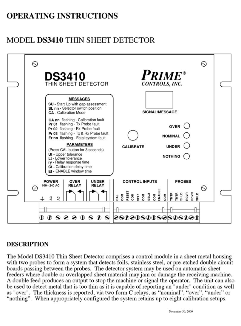
Prime Controls DS3410 User manual

Prime Controls
Prime Controls LH200 User manual

Prime Controls
Prime Controls FLUXIMITY DS71 User manual
Prime Controls
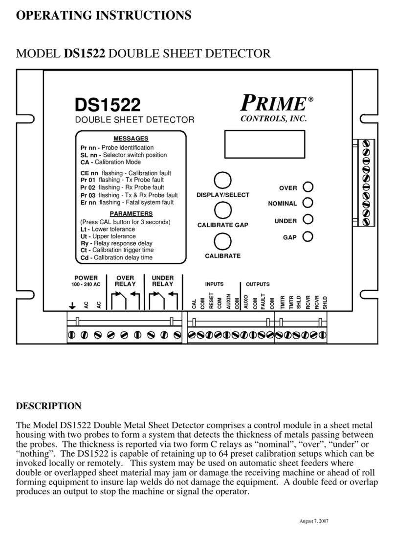
Prime Controls DS1522 User manual
