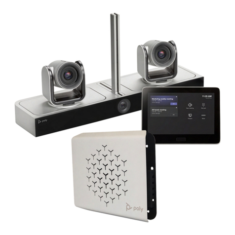
Poly G85-T User manual

Poly G85-T
SETUP SHEET
See the Regulatory Notices for all regulatory and safety guidance prior to configuration.
Avant de procéder à la configuration, veuillez consulter les Avis de réglementation, afin de prendre connaissance des recommandations en matière de sécurité et de réglementation.
Get Started
Before you begin, make sure that you have the following:
Network preparation (See Prepare your environment for Microsoft Teams Rooms)
Microsoft Teams Room License (See your Office 365 Admin Center and Licenses for Microsoft Teams Rooms)
Account credentials (See Configure accounts for Microsoft Teams Rooms)
USB keyboard and mouse
Display HDMI cable(s)
Phillips #1 screwdriver and flathead screwdriver
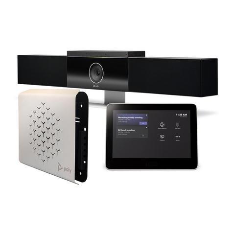
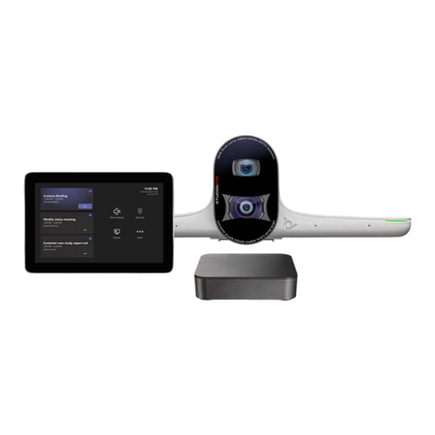
Unpack the Poly GC8, Lenovo® device, mounting kit, 10 m USB-A to USB-C cable, EagleEye Director II, and 5 m USB-A to USB-B cable from their boxes.
support.polycom.com/mtrsetup
For support, go to Poly Support.
For Warranty information, see the Polycom Product Warranty Guide. 3725-30785-085D

(Optional) Mount the Lenovo PC using the mounting kit. Refer to the Poly G10
Series, Poly G40 Series, and Poly G85 Series PC Mounting Kit Setup Sheet.
Remove the bottom panel from the Poly GC8: loosen the screw with a Phillips
#1 screwdriver, turn the GC8 faceup, press the rubber circles on each side,
and slide the panel off.
Remove the cable guard from the Poly GC8 using a flathead screwdriver.
Using the supplied USB-A to USB-C cable, connect the Lenovo PC (USB-A) to
Poly GC8 (USB-C). Refer to the cabling diagram on page 4.
(Optional) Connect an additional PC/laptop for content sharing to Poly GC8
(using an HDMI/HDMI Mini cable).
Replace the cable guard in the Poly GC8 and replace the bottom panel and
tighten the screw.
Using the supplied USB-A to USB-B cable, connect the EagleEye Director II
(USB-B) to the Lenovo PC (USB-A).
Connect a display (using an HDMI cable) to the Lenovo PC.
(Optional) Connect a second display to the Lenovo PC.
(Optional) Connect the Poly-supported DSP to the Lenovo PC using a USB
cable and to the EagleEye Director II using a 3.5 mm audio cable. Connect a
microphone and speaker system to the Poly-supported DSP. The A/V
integrator must route the far end audio to the EagleEye Director II. Refer to
the cabling diagrams on pages 4 and 6.
Connect the Lenovo PC to Ethernet.
Connect the keyboard and mouse to the Lenovo device.
Plug in and power on the Poly GC8 and then plug in and power on the other
components.
The Lenovo device may reboot more than once as it downloads and installs
updates. Do not shut down the Lenovo device during this process.
Complete the Windows Out-of-Box Setup using your keyboard and mouse.
See Initial setup for Microsoft Teams Rooms.
a. Choose your region.
b. Choose your keyboard layout.
c. Select Skip for second keyboard.
The Lenovo device reboots and then loads Microsoft Teams Rooms.
Complete the Microsoft Teams Rooms Out-of-Box Setup.
a. Accept the Microsoft Software License Terms.
b. Enter your Microsoft Teams Rooms account information. See
Configure accounts for Microsoft Teams Rooms.
c. Select the appropriate Supported Meeting Mode based on the preferred
default application.
Skype for Business (default) and Microsoft Teams
Skype for Business and Microsoft Teams (default)
Skype for Business only
d. Enable Modern Authentication.
e. Complete Exchange sign-in if your mailbox has an alternate SMTP
address.
f. Click Finish.
The system restarts.
The Lenovo device may reboot more than once as it downloads and installs
updates. Do not shut down the Lenovo device during this process. When
complete, the Microsoft Teams Rooms Setup screen appears on the GC8.

Complete your configuration. For detailed instructions,
see Initial Setup for Microsoft Teams Rooms.
a. Click More > Settings.
b. Enter admin password: sfb
c. Configure additional settings.
Account: Correct or change the email or password, if needed.
Device: Enable Dual monitor mode if using a second monitor.
Peripherals:
Change audio devices, if necessary.
Speaker for Conferencing and Default Speaker are the same.
When using the "magic whiteboard" functionality, content
cameras can be configured. Note that this is not the People
camera, which is set automatically by the Microsoft Teams Rooms
application. See Content camera for Microsoft Teams Rooms.
When complete, the Lenovo device reboots one more time.
After connecting all peripherals to the system, perform a Windows Update.
When the Poly GC8 requires updates, the screen turns black while the
firmware is updating, which can take up to 5 minutes. After the firmware
updates, the Poly GC8 restarts and returns to regular operation automatically.
Accessibility Features
For information on software accessibility features, see
Accessibility support for Microsoft Teams.
The Poly GC8 provides a 3.5 mm audio out jack so that people who are hard
of hearing can use third-party assistive technology peripherals.
If you connect the optional Poly Trio:
1. When the Poly Trio Choose Base Profile screen appears, select Microsoft
USB Optimized.
2. Pair the Poly Trio system with the Polycom EagleEye Director II camera
system from the local interface.
a. Set up the EagleEye Director II camera system. See the Polycom
EagleEye Director II Setup Sheet on Polycom Support for more
information.
b. On the Poly Trio system, go to Settings > Advanced > Network Devices.
c. Select the filter icon and select the Camera check box.
d. Go to the Network Devices screen.
The last six characters of the EagleEye Director II system's serial
number displays on the Available Devices screen.
e. Select the EagleEye Director II camera system’s serial number.
f. Select Pair on the Details screen.
g. Select Complete.
The EagleEye Director II camera system LED blinks purple when pairing
with the Trio system.
Improving Tracking Accuracy
Once paired and configured, the Trio system adds Acoustic Echo Cancellation
(AEC) functionality that enables the EagleEye Director II
camera to ignore audio output from the Trio system speakers. This results in
better EagleEye Director II camera tracking.
For information on pairing and configuring, see the Poly Trio Systems in
Microsoft Environments Administrator Guide and the Polycom
EagleEye Director II Setup Sheet on Polycom Support.

This product cannot be connected directly to the telecommunications circuits (or public wireless LANs) of any telecommunication carriers (e.g., mobile communications carriers, fixed
communications carriers, or internet providers). In the case of connecting this product to the Internet, be sure to connect it via a router.

Building the EagleEye Director II MONO Far Audio Reference cable
See the diagram on page 6.
The camera system uses a 3.5 mm TRS audio connector for the Far Audio
Reference input and a DSP or Phoenix connector.
The TRS connector consists of the sleeve/common (section of the connector
post closest to the base), the ring/right (in the middle of the connector post),
and the tip/left (at the end of the connector post).
Note that the DSP pinouts may vary. The most common arrangement is that
the pins per port on the DSP or Phoenix connector are (left to right) pin 1:
signal positive, pin 2: signal negative, and pin 3: ground/common.
At the 3.5mm TRS connector, connect one conductor of a shielded twisted
pair audio cable to the tip/left terminal and the other to the ring/right
terminal. The tip carries left audio and the ring carries right audio. Connect
the shield or drain wire to the sleeve/common terminal.
At the DSP or Phoenix connector, connect both conductors of the shielded
twisted pair audio cable to the pin 1 or device appropriate signal positive
position. Connect the shield or drain wire to the pin 3 or device appropriate
ground/common position. Connect nothing to the pin 2 or device appropriate
signal negative position.
Building the EagleEye Director II STEREO Far Audio Reference cable
See the diagram on page 6.
The camera system uses a 3.5 mm TRS audio connector for the Far Audio
Reference input and 2 DSP or Phoenix connectors.
The TRS connector consists of the sleeve/common (section of the connector
post closest to the base), the ring/right (in the middle of the connector post),
and the tip/left (at the end of the connector post).
Note that the DSP pinouts may vary. The most common arrangement is that
the pins per port on the DSP or Phoenix connector are (left to right) pin 1:
signal positive, pin 2: signal negative, and pin 3: ground/common.
At the 3.5mm TRS connector, connect one conductor of a shielded twisted
pair audio cable to the tip/left terminal and the other to the ring/right
terminal. The tip carries left audio and the ring carries right audio. Connect
the shield or drain wire to the sleeve/common terminal.
At the DSP or Phoenix connector for the left signal, connect the conductor of
the shielded twisted pair audio cable that's connected to the tip/left of the 3.5
mm TRS connector to the pin 1 or device appropriate signal positive position.
Connect a shield or drain wire to the pin 3 or device appropriate ground/com-
mon position. Connect nothing to the pin 2 or device appropriate signal
negative position.
At the DSP or Phoenix connector for the right signal, connect the conductor
of the shielded twisted pair audio cable that's connected to the ring/right of
the 3.5 mm TRS connector to the pin 1 or device appropriate signal positive
position. Connect a shield or drain wire to the pin 3 or device appropriate
ground/common position. Connect nothing to the pin 2 or device appropriate
signal negative position.

© 2021 Plantronics, Inc. All rights reserved. Poly, the propeller design, and the Poly logo are trademarks of Plantronics, Inc. The Bluetooth trademark is owned by Bluetooth SIG,
Inc. and any use of the mark by Plantronics, Inc. is under license. All other trademarks are the property of their respective owners.
Other Poly Conference System manuals

Poly
Poly Studio User manual

Poly
Poly G10-T Manual

Poly
Poly G7500 Service manual

Poly
Poly Trio 8800 User manual

Poly
Poly G7500 User manual

Poly
Poly Polycom RealPresence Group Series User manual

Poly
Poly G200 Service manual

Poly
Poly P009 User manual

Poly
Poly Studio R30 User manual

Poly
Poly Studio P21 User manual
Popular Conference System manuals by other brands

Tadiran Telecom
Tadiran Telecom FlexSet 120S user guide

Grandstream Networks
Grandstream Networks GVC3220 Administration guide

Graco
Graco 25B127 Instructions - parts

TANDBERG
TANDBERG Codec C90 D14306.01 user guide

Mitel
Mitel Navigator 3300 ICP General Information Guide

Sony
Sony BRU-300 operating instructions