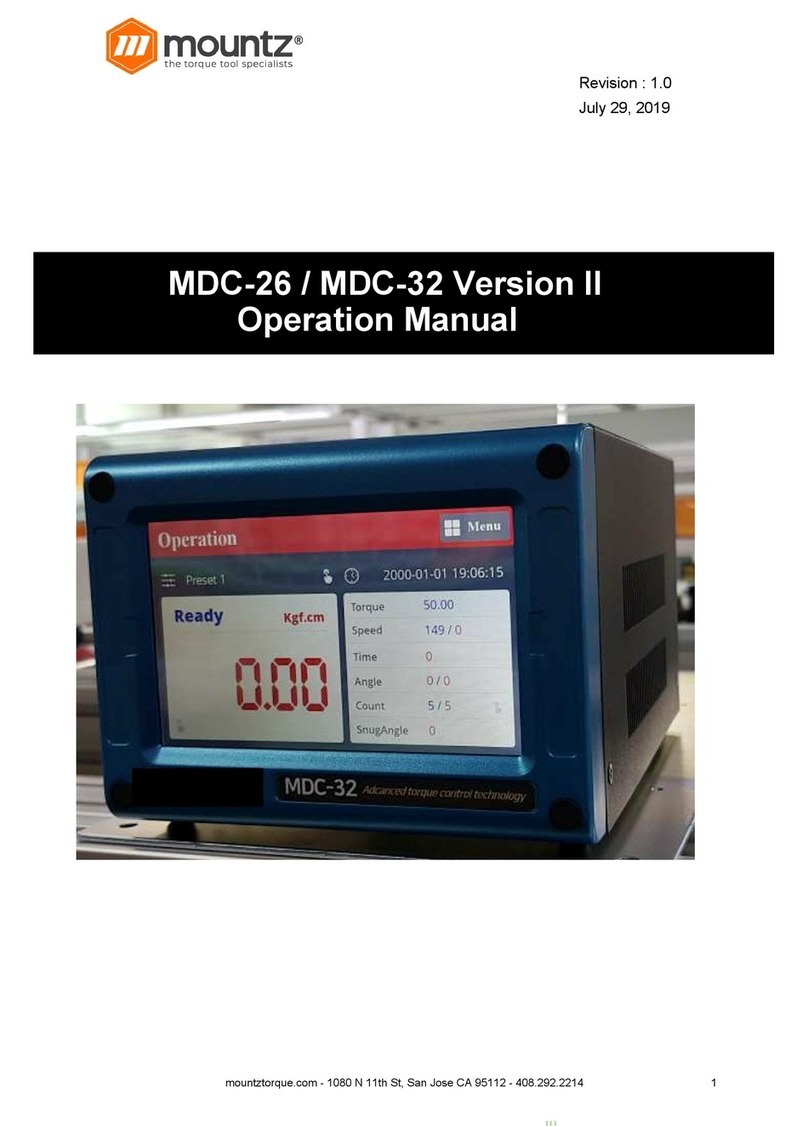
Mountz DPC Touch V2 User manual

mountztorque.com – 1080 N 11th St – San Jose CA 95112
DPC$Touch$
V2$
OPERATION MANUAL
(Differences VS DPC Version 1 highlighted in YELLOW)

mountztorque.com – 1080 N 11th St – San Jose CA 95112
IMPORTANT
The controller delivered with this
manual may be modified for specific needs.
In this case, please give us the controller serial number written on our shipping note or the
approximate controller delivery date when you will place an order for a new similar controller or for
spare parts.
In this way, you will be sure to get the required controller and/or spare parts.
WARNING
This information has to be kept in a location known to all users.
Each operator has to read carefully this instructions manual before installing,
using, and mending the product.
Be sure that the operator has understood usage recommendations and the meaning of signs put on
the product.
Most accidents could be avoided respecting this Instructions Manual. As a matter of fact, they were
created according to European laws and norms applied to the product.
In each case, please respect and follow national safety norms. Do not take off nor damage the
stickers or notifications put on the product and above all the details imposed by the law.

mountztorque.com – 1080 N 11th St – San Jose CA 95112
1. SUMMARY
2. SPECIFICATIONS ...................................................................................................................... 3
3. HARDWARE ............................................................................................................................. 4
3.1 Dimensions and mounting interface ..................................................................................... 4
3.2 Interface ports ....................................................................................................................... 5
4. GETTING STARTED ................................................................................................................... 6
5. MAIN MENU ............................................................................................................................ 6
6. JOB MANAGER ........................................................................................................................ 7
7. NEW JOB CREATION ................................................................................................................ 8
7.1 Fastening step creation ......................................................................................................... 9
6.1.1 Manual programming of fastening step: ............................................................................. 11
6.1.2 Automatic programming of fastening step: ......................................................................... 12
6.1.3 Smart tolerance detection feature: ..................................................................................... 12
7.2 Logical Input step creation .................................................................................................. 13
7.3 Logical Output step creation ............................................................................................... 14
7.4 Delay step creation .............................................................................................................. 15
7.5 Message step creation ........................................................................................................ 16
7.6 Job example ......................................................................................................................... 17
8. SETTINGS ............................................................................................................................... 18
8.1 Operating ............................................................................................................................ 18
8.2 Encoders .............................................................................................................................. 20
8.3 Inputs .................................................................................................................................. 22
8.4 Outputs ................................................................................................................................ 24
8.5 Network ............................................................................................................................... 25
8.6 Other ..................................................................................................................................... 3
9. OPERATING MODE .................................................................................................................. 4
10. ELECTRICAL WIRING ................................................................................................................ 5
10.1 Encoder’s port wiring scheme ............................................................................................... 5
10.2 RS232 port wiring scheme ..................................................................................................... 5
10.3 Inputs wiring scheme ............................................................................................................ 6
10.4 Outputs wiring scheme ......................................................................................................... 7
10.5 Connection Mountz low voltage tools BF, NF, LF and HF ...................................................... 8
10.6 Connection to Mountz current control MDC series .............................................................. 9
10.7 Connection of Atlas PF4000 ................................................................................................ 10
10.8 Connection of Stanley Alpha and Kappa tools .................................................................... 11
10.9 Automation equipment wiring example ............................................................................. 12
10.10 I/O port adaptor (DB44 à DB25 + DB9) wiring scheme ................................................. 13
11. Troubleshooting .................................................................................................................... 14

mountztorque.com – 1080 N 11th St – San Jose CA 95112
2. SPECIFICATIONS-
No
Spécifications
1. Input power
DC24V, 1A
AC 100-240V / DC 24V adaptor is provided
2. Dimensions
202(W) x 128(H) x 38(D) mm
3. Weight
0.55 kg
4. Screen
7” LCD Touch screen, 800 x 480 px
5. Graphical interface
Visualization of assembly process with graphical instructions
6. Inputs and Outputs 24V
12 inputs and 12 outputs with assignable functions
Logical I/O’s for workstation automation
7. Analog encoders
4 channels, 0...5V
8. Memory card
Removable SD card, 8Gb
9. Total jobs memory
255 jobs with open structure
10. Total positions memory
255 jobs x 80 steps x 50 positions per fastening step
max 999 positions in one job (counter limit)
11. Programming
Automatic and manual programming of a Fastening step
12. Positioning accuracy
0.09° for angular encoders
<0.5 mm for linear encoders
13. Positioning tolerance
Adjustable for each position and for each axis.
Smart tolerance detection feature.
14. Compatible tools
All tool with signals – electric or pneumatic.
Min required signals: «Fastening OK», «Tool Lock»
15. Communication
RS232 for bar code scanner and firmware upgrade
Ethernet

mountztorque.com – 1080 N 11th St – San Jose CA 95112
3. HARDWARE-
!"# $%&'()%*()+,(-+&*.(/%(0+%(/'12,3'+
Mounting plate with 4 x M3 screws is delivered with the controller as a standard accessory.
Weight of the controller: 0.55 kg

mountztorque.com – 1080 N 11th St – San Jose CA 95112
!"4 5(/'12,3'+6*1/)+
NOTE: ports shown in grey are disabled
I/O port adaptor
This adaptor is used to split I/O signals for tool interface and other automation equipment (see
Electric wiring chapter for the wiring scheme).
Ethernet port
I/O port DB44
Encoders
RS232
SD card
1:GX,GY,DO,GA
2:GX,GY,DO,GA
Power supply
USB mini-B port
USB-B port

mountztorque.com – 1080 N 11th St – San Jose CA 95112
4. GETTING-STARTED-
1. Connect power supply to the controller to turn it on. Normal booting time is about 2 sec. If
the controller is not booted, the last booting step indicates the problem (e.g. “Init SD Card…”
- missing or damaged SD card).
2. Controller is started automatically in operating mode. If default job is defined it will start
automatically.
3. Tap on the HOME button in order to access to the main menu screen. While not logged in,
JOB MANAGER and SETTINGS are not fully accessible.
4. To log into the system tap on the LOGIN button. Default factory password is “0”.
NOTE: if the password is “0”, there is no need to enter it, just press OK button directly.
5. MAIN-MENU-
The main screen provides access to the main menu with four buttons:
- Job manager
Provides access to the list of saved jobs and allows creation/modification of jobs. This menu
is partially locked while user is logged out.
- Operation mode
Provides access to the operating screen (normal work mode).
- Settings
Provides access to the controller settings. This button is locked while the user is logged out.
- Login/Logout
Allows logging into the system by entering the password to access and modify Job manager
and Settings.

mountztorque.com – 1080 N 11th St – San Jose CA 95112
6. JOB-MANAGER-
Job manager interface provides access to the list of saved jobs. It also allows to Edit or to Delete
saved jobs as well as to create new ones by pressing New button or by Copying an existing job.
Load button is used to load selected job into operating mode.
NOTE: a job can’t be loaded or renamed if it doesn’t contain any steps.
Each job has its sequential number (№). In order to change job number tap one more time on the
selected job and then change its position in the list by using Up and Down buttons.
For information purposes number of steps and screws in a job is displayed in corresponding line in
the list.
Home button provides access to the main menu screen.
Maximum number of jobs is 255.
NOTE: while not logged in, the only active buttons are Load and Home, other buttons are locked.

mountztorque.com – 1080 N 11th St – San Jose CA 95112
7. NEW-JOB-CREATION-
While in Job Manager screen, press NEW button. New job will be created and placed in the end of
the list. New job creation screen will be displayed automatically.
A job is represented by a sequence of steps. These steps can be organized in any order which
corresponds to the desired production sequence. There are 5 types of steps and each one of them
can be used multiple times if necessary.
- Fastening: this step contains fastening positions including information associated with these
positions (positioning tolerance, tightening program, tightening time, etc.)
- Logical In: this step is used to verify an input signal in order to pass to the next step (e.g.
signals from proximity sensors, buttons, etc.).
- Logical Out: this step is used to send an output signal(s) to manage automation equipment
on work station (e.g. activation of pneumatic valves, lights, etc.).
- Delay: this step allows to maintain the current state of I/O’s for specified time (e.g. a delay
required between receiving an input signal and sending an output signal, bar code,
confirmation).
- Message: this step is used to display a graphical or text message on the operating screen
during working cycle.
A job may contain up to 80 steps. The maximum number of positions in a single fastening step is 50.
In order to change sequence of steps in a job, tap one more time on the selected step and then
change its position in the list by using Up and Down buttons.
Created steps can be modified by using EDIT button or deleted by using DELETE button. COPY button
creates a copy of the selected step and inserts it in the end of the list.
Press SAVE button to save the job or CANCEL button to quit programming without saving changes.
Job index : 3

mountztorque.com – 1080 N 11th St – San Jose CA 95112
7"# 8,)/'(%(0+)/'6+31',/%*(+
NOTE: it is useful to define encoder’s reference point before creating a fastening step. See encoder’s
settings for more information.
While in Job creation screen, tap on FASTENING step button. The Fastening step creation screen will
appear.
Position Current field displays the number of position being programmed.
Position Saved field displays the total number of saved position in the fastening step being
programmed.
Position Manager Current channels fields display current values from analog encoders. Only active
channels are shown.
Position Manager Saved channels fields display saved values from analog encoders. Current values
are saved when Apply button is pressed or when Fastening OK signal is received.
Tolerance fields display tolerance values for analogue encoders to be applied for each encoder for
the current position. Tolerance values can be automatically detected by using Smart Tolerance
detection feature (please refer to corresponding chapter for more details).
Approaching area (orange):
Tool is disabled
OK zone (green):
tool can be enabled
Out of position area (red):
Tool is disabled
Screw

mountztorque.com – 1080 N 11th St – San Jose CA 95112
NOTE: real shapes of tolerance areas are not circular; they depend on the geometry of the
positioning arm being used. To avoid overlapping of tolerance areas of different screws, keep
tolerance values as low as possible.
Time control fields display measured Tightening time and calculated Min and Max limits. Min and
Max values are calculated according to percentages defined in operating settings.
Tightening job is a preset number to be selected for the current tightening position via 24V outputs
(direct or binary logic) if supported by the tool.
Retightening job is similar to the Tightening job but it is used only for rework operation and it is
automatically selected after NG tightening (if retightening is enabled in operating settings).
Pick up positions 1 and 2 can be selected to allow to start the tool in a specific position or area
(outside position OK zone) in order to pick up a screw. Fastening OK signals and Motor run signals are
not effective on pick-up position.
Driver 1 and 2 selection is only applied to Mountz tools (NF, BF, LF and HF) connected through RJ45
port. This selection allows enabling and disabling tools for each individual position.
Reset button is used to reset current position data to default values.
Delete button is used to delete the current position, with a confirmation «Are you sure?».
Select Image button is used to add images in fastening steps, and add the different screw directly on
it. The position will appears according to the fastening sequence, and change color according to
encoders.
- Image list : select the .JPG file 800x400 on the SD card (/Images).
- Screw list : select the position to place it directly on the picture, it can adjusted precisly with arrow
Up and Down, Left and Right.
- Circle size : allow to increase the size of the circle
- Circle color : allow to change the color of the circle to increase it’s visibility
NOTE: there is no need to use APPLY button after modification of any of the above values. APPLY
button is only used to save current values from encoders for the current position.
A Fastening step can be programmed manually or automatically.

mountztorque.com – 1080 N 11th St – San Jose CA 95112
6.1.1$Manual$programming$of$fastening$step:$
0. Optional: Use Smart tolerance detection feature (refer to Smart tolerance detection below)
1. Position the arm on the first screw.
Encoders monitoring fields are displaying the current position of the arm.
2. Press APPLY button to save current position of the arm. Saved values from encoders will be
displayed in corresponding fields. If not satisfied with the result press APPLY button again to
rewrite saved values from encoders.
3. Default tolerance values for the approaching Area and for the OK zone are applied. To
change default values refer to encoders’ settings. Tolerance values can be adjusted manually
for each individual position or by using Smart tolerance detection feature.
4. If necessary, define Tightening and Retightening programs to be used for the current
position, feeding point (see Pick Up positions in encoders’ settings) and the screwdriver to be
used for this tightening position (used only for Mountz (NF,BF, LF and HF tools).
5. If necessary, enter Min and Max tightening time limits in corresponding fields. Tightening
time control is not used if limits are equal to 0.
6. Press NEXT button to pass to the next position.
7. Repeat 1-6 for each position.
8. Activate Non-sequential mode if there is no need to keep strict tightening sequence.
NOTE: in non-sequential mode, retightening can’t be managed.
9. Press SAVE button to save the step or CANCEL button to quit programming without saving
changes.

mountztorque.com – 1080 N 11th St – San Jose CA 95112
6.1.2$Automatic$programming$of$fastening$step:$
For automatic programming, make sure that the tool is connected to the controller and signals are
correctly assigned. In order to register tightening time, Motor run and Fastening OK signals have to
be connected.
0. Optional: Use Smart tolerance detection feature (refer to Smart tolerance detection below)
1. Position the arm on the first screw.
Monitoring fields are displaying the current position of the arm.
2. Default tolerance values for the approaching Area and for the OK zone will be applied. To
change default values refer to encoders settings. Tolerance values can be adjusted manually
for each individual position or by using Smart tolerance detection feature.
3. If necessary, define Tightening and Retightening programs to be used for the current
position, feeding point (see Pick Up position in encoders’ settings) and the tool being used.
4. Perform a tightening operation as it has to be performed during production.
5. Tightening time will be registered automatically. Min and Max tightening time limits are
calculated automatically by using default values in operating settings. Tightening time control
is not used if limits are equal to 0.
6. Repeat 1-5 for each position.
7. Activate Non-sequential mode if there is no need to keep strict tightening sequence.
NOTE: in non-sequential mode, retightening can’t be managed.
8. Press SAVE button to save the step or CANCEL button to quit programming without saving
changes.
6.1.3$Smart$tolerance$detection$feature:$
This feature allows automatic detection of OK zone tolerance for each position. Motor Run signal has
to be connected in order to use this feature.
1. Press START button to begin smart tolerance detection.
2. Start the tool and move it around the screw to define OK zone (the zone where operator is
allowed to run the tool).
3. Stop the tool and press STOP button on the screen.
Or perform a tightening operation as it has to be performed during production.
In this case tightening time will be saved automatically together with detected tolerance
values and current position coordinates. Next position teaching will start automatically.
4. Continue with Manual or Automatic programming.

mountztorque.com – 1080 N 11th St – San Jose CA 95112
7"4 9*0%3,:+5(6./+)/'6+31',/%*(+
While in Job modification screen, tap on LOGICAL IN button. The Logical In step creation screen will
appear. Select an available input from the list of Inputs. If an Input was assigned for a specific
function in Input settings it is not available to be used as a logical signal.
Select the type of the signal. There are four types of input signals:
- Active High: for this type of signal it is necessary to detect a transition from 0 to 1.
- Active Low: for this type of signal it is necessary to detect a transition from 1 to 0.
- Status High: for this type of signal it is enough to detect if the signal is equal to 1.
- Status Low: for this type of signal it is enough to detect if the signal is equal to 0.
Logical input step is completed if the corresponding input signal matches the condition of the
selected signal type.
If two or more signals are selected, then AND condition will be applied for selected signals to
complete the step.
Press SAVE button to save the step or CANCEL button to quit programming without saving changes.

mountztorque.com – 1080 N 11th St – San Jose CA 95112
7"! 9*0%3,:+;./6./+)/'6+31',/%*(+
While in Job modification screen, tap on LOGICAL OUT button. The Logical Out step creation screen
will appear.
Select an available output and its type from the list of Outputs. If an Output was assigned for a
specific function in Output settings it is not available to be used as a logical signal.
There are three types of output signals:
- Continuous ON: the signal is continuous until it is deactivated in the next Logical Out step. To
deactivate the signal, create a new Logical Out step and deselect the corresponding signal.
- Impulse: the signal is an impulse with defined duration. Duration of the signal is defined in
ms.
- Flashing (select both above) : the signal will be blinking until it is deactivated in the next
Logical Out step. Duration between two flashing signal is defined in ms in the impluse
duration field.
Multiple output signals can be used in the same Logical Out step.
Press SAVE button to save the step or CANCEL button to quit programming without saving changes.

mountztorque.com – 1080 N 11th St – San Jose CA 95112
7"< $':,=+)/'6+31',/%*(+
While in Job modification screen, tap on DELAY button. The Delay step creation screen will appear.
There are three types of delay step :
- Delay time : The controller will stay on hold for the defined time. Delay step can be used to manage
timing between Logical In and Logical Out steps or between messages.
- Barcode : Enter the barcode to enter (until 32 alphanumerical characters) and filter it according to
the number of digit. Example : Barcode «ABCDE», start will be «1» and end is «5». If filter are «0»
and «0», all barcode are accepted. Barcode can be typed manually with the keyboard, or with a
barecode reader.
- Confirmation : User will see a confirmation message Box «Are you Sure?».
Press SAVE button to save the step or CANCEL button to quit programming without saving changes.

mountztorque.com – 1080 N 11th St – San Jose CA 95112
7"> ?')),0'+)/'6+31',/%*(+
While in Job modification screen, tap on MESSAGE button. The message step creation screen will
appear.
Enter the text to be displayed on the operation screen and activate the corresponding switch.
Select an image to be displayed from the list of available images and activate the corresponding
switch.
To hide the displayed message it is necessary to create a new Message step without text and/or
image.
Images are stored on SD card in the following directory: SD:\images
For the best result, use pictures with the following format: 800 x 480 px, .JPG
Press SAVE button to save the step or CANCEL button to quit programming without saving changes.

mountztorque.com – 1080 N 11th St – San Jose CA 95112
7"@ A*B+'C,&6:'+
A simple job may contain only a Fastening step, which will assure screws counting and tool position
control functions.
Example below illustrates a job for management of an automated station with multiple sensors and
actuators.
This job uses 5 logical inputs, 4 logical outputs, 7 messages (text and/or image) and 2 fastening steps.
No
Step type
Step functions
1
Message
Text or Image message appears on the screen to indicate what workpiece
has to be assembled. Image stays on the screen until replaced by next
message or until screen is touched.
2
Logical In
Three input signals (active high) are expected from proximity switch to
detect presence of the workpiece on the table and from two buttons which
operator has to press simultaneously in order to keep his hands off the
clamping device.
3
Message
Text or Image message is shown on the screen to worn the operator about
closing clamping device.
4
Delay
A short delay is used before activation of the clamping device.
5
Logical Out
Two output signals (continuous) are sent to activate the clamping device to
lock the workpiece on the table and to turn on assembly status light.
6
Message
Text or Image message is shown on the screen to indicate parts to be picked
7
Logical Out
One output signal (continuous) is sent to turn on pick to light indicator 1
8
Logical In
One input signal (active high) is expected for picking verification by sensor 1
9
Logical Out
Pick to light indicator 1 is turned off once picking is performed
10
Message
Text or Image message is shown on the screen to indicate first fastening
operations to be performed.
11
Fastening
First fastening operations are performed, screws are counted and tool
position is assured.
12
Message
Text or Image message is shown on the screen to indicate parts to be picked
13
Logical Out
One output signal (continuous) is sent to turn on pick to light indicator 2
14
Logical In
One input signal (active high) is expected for picking verification by sensor 2
15
Logical Out
Pick to light indicator 2 is turned off once picking is performed
16
Message
Another message is shown on the screen to indicate second fastening
operations to be performed.
17
Fastening
Second fastening operations are performed, screws are counted and tool
position is assured.
18
Logical Out
Two output signals are disabled to open the clamping device and to turn off
assembly status light.
19
Message
Job completion message
20
Delay
Delay before the job is restarted
-

mountztorque.com – 1080 N 11th St – San Jose CA 95112
8. SETTINGS-
D"# ;6'1,/%(0+
Screen 1 of 5: Management of interface
Parameter
Description
Range
Default
value
Tool selection
Select one of the following option:
- NF, BF, LF, HF: Mountz low voltage tools (XS-40D, XS-
38D, XT-30D, XS-35D, XT-35D)
- DC tools: all electric digital control tools equipped with
24V I/O signals
-
DC tools
Screws
counting
up/down
This parameter manages counting display. Turn it ON to
count up (1,2,3,…) or OFF to count down (...,3,2,1)
ON/OFF
ON
Screws
counting for
step/job
This parameter manages counting display. Turn it ON to
display counting separately for each step or OFF to
display counting for the whole job.
ON/OFF
ON
Torque
selection by
binary outputs
Selection of tightening presets for each position is done
via Torque selection outputs. These outputs can function
in binary logic or in direct logic (one output per preset).
ON/OFF
ON
Job selection by
binary inputs
Selection of Jobs of DPC Touch can be done via Job
selection inputs. These inputs can function in binary logic
or in direct logic (one input per job).
ON/OFF
ON
Default job
number
Default job is a job which is automatically started after
booting of DPC Touch. If default job number is set to 0,
DPC Touch will not boot any jobs.
NOTE: job selection via inputs has higher priority
0 - 255
0
Screen 2 of 5: Management of buttons in operating mode
Skip button
access without
password
Enables access to Skip button without entering password.
If turned OFF the password will be asked when Skip
button is pressed.
ON/OFF
ON
Back button
access without
password
Enables access to Back button without entering
password. If turned OFF the password will be asked when
Back button is pressed.
ON/OFF
ON
Reset button
access without
password
Enables access to Reset button without entering
password. If turned OFF the password will be asked when
Reset button is pressed.
ON/OFF
ON
Job selection
access without
password
Enables access to Jobs selection without entering
password. If turned OFF the password will be asked when
Job selection button is pressed.
ON/OFF
ON
Display job
reset button
Job reset button can be displayed or hidden by using this
parameter.
NOTE: if turned OFF and automatic reset is used, then the
current step will be reset instead of the current job.
ON/OFF
ON

mountztorque.com – 1080 N 11th St – San Jose CA 95112
Screen 3 of 5: Management of fastening time
Min fastening
time limit, %
Lower limit of fastening time control in percentage of
actual fastening time detected during programming.
NOTE: changes will be applied only to new jobs, existing
jobs won’t be affected.
0 - 100
25
Max fastening
time limit, %
Upper limit of fastening time control in percentage of
actual fastening time detected during programming.
NOTE: changes will be applied only to new jobs, existing
jobs won’t be affected.
0 - 100
25
Start trigger
release time
limit, ms
Fastening time threshold after which trigger release will
be considered as NG tightening. Error message “Trigger
released before Torque Up” will appear.
0 - 9999
0
Temporary
position loss
time, ms
If fastening is started (Motor Run signal is received), then
it is allowed to exit position OK zone (green) into
approaching area (orange) for the specified time without
locking the tool. If this time limit is passed the tool will be
instantly locked. If position NOK zone (red) is entered the
tool will be instantly locked.
NOTE: this parameter is used to avoid interruptions of
fastening process when position is lost for short time due
to vibrations.
0 - 3000
50
Judging time,
ms
Judging time is used if Fastening OK signal is delayed after
the fall of Motor run signal.
0 - 500
100
Screen 4 of 5: Management of NG tightenings
Number of
retightenings
on a position
Maximum number of attempts to rework a NG fastening.
If the maximum number of attempts is reached the
current position can be skipped or Job/Step can be reset
according to parameters selected.
NOTE: this parameter is not effective in non-sequential
assembly mode.
0 - 10
1
Skip NG
tightening
Allows to skip automatically a NG tightening if rework is
not allowed or if rework wasn’t successful.
ON/OFF
OFF
Fastening NG
signal if
position
skipped
If turned ON, Fastening NG signal will be provided when a
position is skipped automatically, by Skip button on the
operating screen or by external input. If turned OFF,
Fastening OK signal will be provided.
ON/OFF
ON
Auto reset
delay, ms
Alarm can be reset automatically after the specified
delay. If delay is equal to 0 than reset has to be done
manually or by external input.
0 - 9999
3000
Screen 5 of 5: Management of operating options
Automatically
restart the job
when finished
If turned ON, the job will restart automatically when
finished
ON/OFF
ON
Store logs
during
operation
If turned ON, all the events will be stored on the SD card
(/Logs) , One folder per year, One sub folder per month,
One .csv file per day
ON/OFF
ON
Skip by step
Skip the complete step instead of position
ON/OFF
OFF
Table of contents
Other Mountz Control System manuals
Popular Control System manuals by other brands

System air
System air Topvex SoftCooler TR09-15 Operation and maintenance instruction

BENDIXKing
BENDIXKing Skymap IIIC pilot's guide

Contro l4
Contro l4 Onyx user guide

A/DA
A/DA PLATINUM II owner's manual

Landi Renzo
Landi Renzo A1 V05 Installation and adjustment manual

Aqua Control
Aqua Control C4115 manual