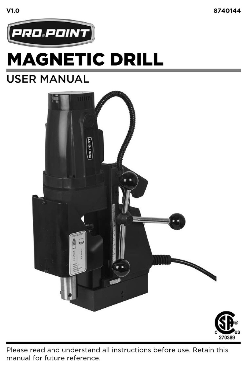
V1.0 Magnetic Drilling and Tapping Press 9027525
Visit www.princessauto.com for more information 3
WARNING! This notice indicates a specific hazard or unsafe practice that
could result in severe personal injury or death if the proper
precautions are not taken.
CAUTION! This notice indicates a potentially hazardous situation that may
result in minor or moderate injury if proper practices are not
taken.
NOTICE! This notice indicates that a specific hazard or unsafe practice
will result in equipment or property damage, but not
personal injury.
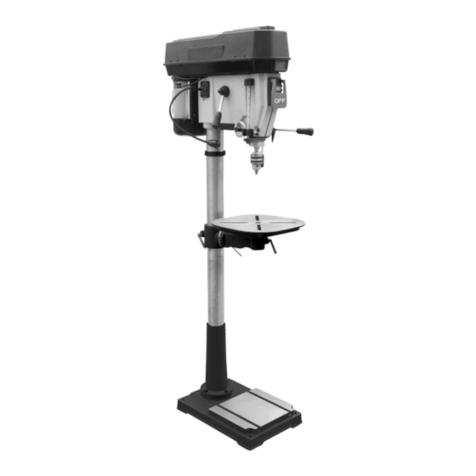
This magnetic drilling and tapping press features a 2 HP motor and 2-gear
variable speeds with speed ratings of 100 to 265 RPM and 200 to 500
RPM. Use with annular cutters, twist drill bits and Weldon shank drill and
taps to drill holes and threads in a variety of material.
The intended use of this tool is to drill holes in ferrous metals. The magnet
is intended to hold the drill in place whilst the drill is functioning. It is
designed for use in fabrication, construction, railways, petro chemical, and
any other applications when drilling ferrous metals. Any deviation from its
intended use will not be covered by warranty.
WARNING! When using electric tools, basic safety
precautions should always be followed to reduce
the risk of fire, electric shock and personal
injury, including the following. Please read these
instructions before attempting to operate the
machine.
Keep this manual for safety warnings, precautions, operating or inspection
and maintenance instructions.
1. Remove the power supply before carrying out any adjustment,
servicing or maintenance.
2. Keep work area clear—cluttered areas and benches invite injuries.
3. Consider the work area environment:
3.1 Do not expose tool to rain.
