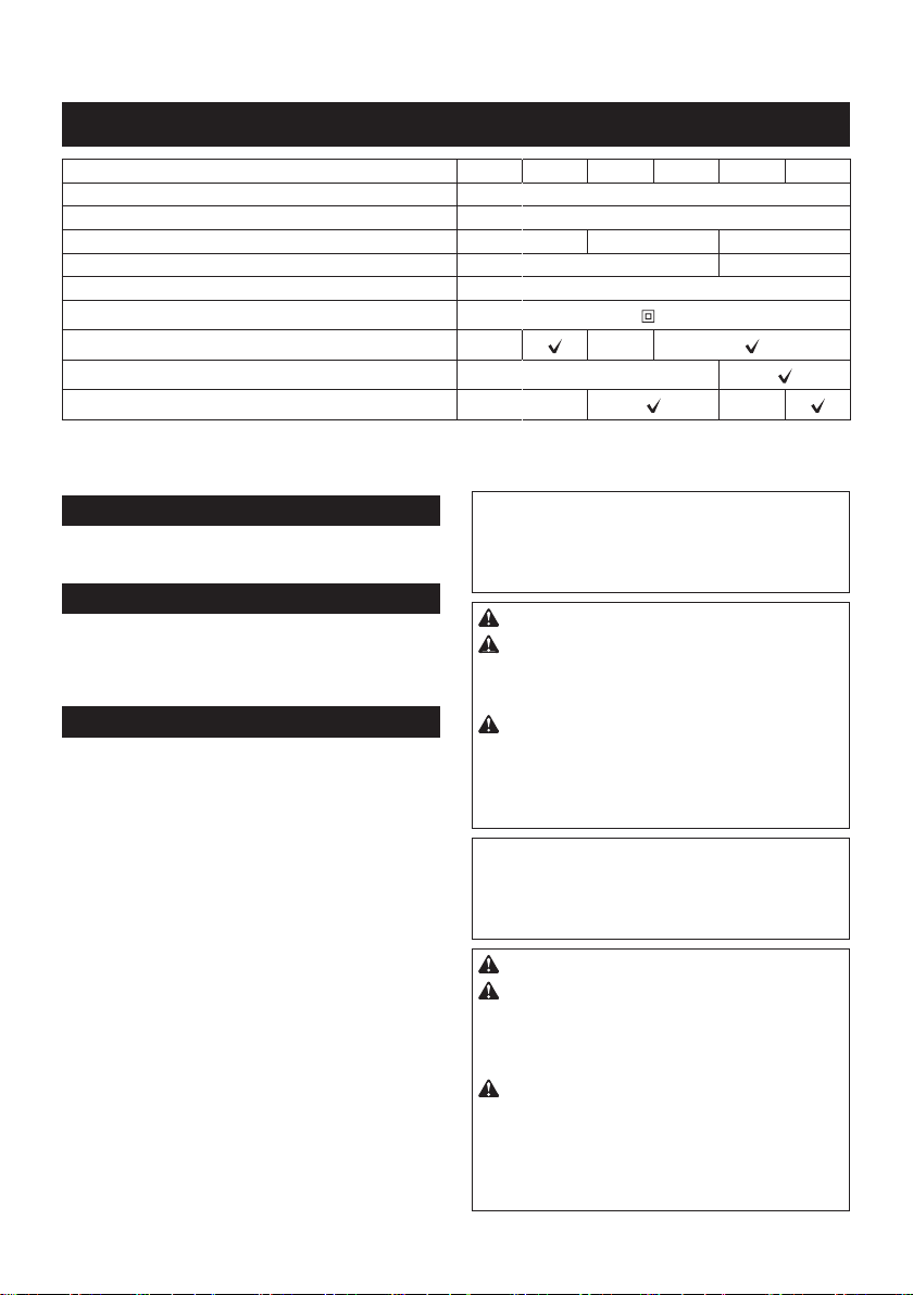
Makita RP1803 User manual

RP1802
RP1802F
RP1803
RP1803F
RP2302FC
RP2303FC
EN Router INSTRUCTION MANUAL 9
FR Défonceuse MANUEL D’INSTRUCTIONS 17
DE Oberfräse BETRIEBSANLEITUNG 26
IT Fresatrice verticale ISTRUZIONI PER L’USO 35
NL Bovenfrees GEBRUIKSAANWIJZING 44
ES Rebajadora MANUAL DE
INSTRUCCIONES 53
PT Tupia MANUAL DE INSTRUÇÕES 62
DA Overfræser BRUGSANVISNING 71
EL 79
TR Freze KULLANMA KILAVUZU 88

4
7
8
15
6
2
3
Fig.1
1
Fig.2
1
2
3
Fig.3
1
2
Fig.4
1
Fig.5
1
Fig.6
1
Fig.7
1
2
3
4
Fig.8
2

1
Fig.9
Fig.10
1
2
3
44
2
Fig.11
1
23
4
Fig.12
1
2
3
4
5
Fig.13
C1
A
B
2
Fig.14
Fig.15
1
2
3
Fig.16
3

1
2
3
Fig.17
1
Fig.18
Fig.19
Fig.20
Fig.21
1
2
Fig.22
1
2
3
5
6
4
(X)
Fig.23
1
Fig.24
4

1
2
3
45
6
Fig.25
3
1
2
Fig.26
1
2
Fig.27
Fig.28
1
2
Fig.29
2
1
Fig.30
1
Fig.31
1
2
Fig.32
5

1
Fig.33
1
Fig.34
1
Fig.35
Fig.36
R
Fig.37
Fig.38
Fig.39
Fig.40
6

Fig.41
Fig.42
Fig.43
Fig.44
Fig.45
Fig.46
Fig.47
Fig.48
7

Fig.49
Fig.50
8

9ENGLISH
ENGLISH (Original instructions)
SPECIFICATIONS
Model: RP1802
RP1802F
RP1803
RP1803F
RP2302FC RP2303FC
Collet chuck capacity
Plunge capacity 0 - 70 mm
No load speed 23,000 min-1 22,000 min-1 9,000 - 23,000 min-1
Overall height 312 mm 327 mm
Net weight 6.2 kg
Safety class /II
Lamp --
Speed adjusting dial -
Electric brake - -
•
• Weight according to EPTA-Procedure 01/2014
Intended use
wood, plastic and similar materials.
Power supply
The tool should be connected only to a power supply of the same
voltage as indicated on the nameplate, and can only be operated
on single-phase AC supply. They are double-insulated and can,
therefore, also be used from sockets without earth wire.
Noise
The typical A-weighted noise level determined accord-
ing to EN62841-2-17:
Model RP1802
Sound pressure level (LpA) : 85 dB(A)
Sound power level (LWA) : 96 dB (A)
Uncertainty (K) : 3 dB(A)
Model RP1802F
Sound pressure level (LpA) : 85 dB(A)
Sound power level (LWA) : 96 dB (A)
Uncertainty (K) : 3 dB(A)
Model RP1803
Sound pressure level (LpA) : 85 dB(A)
Sound power level (LWA) : 96 dB (A)
Uncertainty (K) : 3 dB(A)
Model RP1803F
Sound pressure level (LpA) : 85 dB(A)
Sound power level (LWA) : 96 dB (A)
Uncertainty (K) : 3 dB(A)
Model RP2302FC
Sound pressure level (LpA) : 88 dB(A)
Sound power level (LWA) : 99 dB (A)
Uncertainty (K) : 3 dB(A)
Model RP2303FC
Sound pressure level (LpA) : 88 dB(A)
Sound power level (LWA) : 99 dB (A)
Uncertainty (K) : 3 dB(A)
NOTE:
The declared noise emission value(s) has been
measured in accordance with a standard test method
and may be used for comparing one tool with another.
NOTE:
The declared noise emission value(s) may
also be used in a preliminary assessment of exposure.
WARNING: Wear ear protection.
WARNING:
The noise emission during actual
value(s) depending on the ways in which the tool is
used especially what kind of workpiece is processed.
WARNING:
Be sure to identify safety measures
to protect the operator that are based on an estima-
tion of exposure in the actual conditions of use (tak-
ing account of all parts of the operating cycle such
it is running idle in addition to the trigger time).
NOTE:
The declared noise emission value(s) has been
measured in accordance with a standard test method
and may be used for comparing one tool with another.
NOTE:
The declared noise emission value(s) may
also be used in a preliminary assessment of exposure.
WARNING: Wear ear protection.
WARNING: The noise emission during actual
value(s) depending on the ways in which the
tool is used especially what kind of workpiece is
processed.
WARNING: Be sure to identify safety mea-
sures to protect the operator that are based on an
estimation of exposure in the actual conditions of
use (taking account of all parts of the operating
cycle such as the times when the tool is switched
trigger time).

10 ENGLISH
Vibration
The vibration total value (tri-axial vector sum) deter-
mined according to EN62841-2-17:
Model RP1802
Work mode: cutting grooves in MDF
Vibration emission (ah) : 5.1 m/s2
Uncertainty (K) : 1.5 m/s2
Model RP1802F
Work mode: cutting grooves in MDF
Vibration emission (ah) : 5.1 m/s2
Uncertainty (K) : 1.5 m/s2
Model RP1803
Work mode: cutting grooves in MDF
Vibration emission (ah) : 5.1 m/s2
Uncertainty (K) : 1.5 m/s2
Model RP1803F
Work mode: cutting grooves in MDF
Vibration emission (ah) : 5.1 m/s2
Uncertainty (K) : 1.5 m/s2
Model RP2302FC
Work mode: cutting grooves in MDF
Vibration emission (ah) : 4.2 m/s2
Uncertainty (K) : 1.5 m/s2
Model RP2303FC
Work mode: cutting grooves in MDF
Vibration emission (ah) : 4.2 m/s2
Uncertainty (K) : 1.5 m/s2
NOTE: The declared vibration total value(s) has been
measured in accordance with a standard test method
and may be used for comparing one tool with another.
NOTE: The declared vibration total value(s) may also
be used in a preliminary assessment of exposure.
WARNING:
The vibration emission during actual
-
ue(s) depending on the ways in which the tool is used
especially what kind of workpiece is processed.
WARNING:
Be sure to identify safety measures
to protect the operator that are based on an estima-
tion of exposure in the actual conditions of use (tak-
ing account of all parts of the operating cycle such
it is running idle in addition to the trigger time).
EC Declaration of Conformity
For European countries only
The EC declaration of conformity is included as Annex A
to this instruction manual.
SAFETY WARNINGS
General power tool safety warnings
WARNING: Read all safety warnings, instruc-
with this power tool. Failure to follow all instructions
serious injury.
Save all warnings and instruc-
tions for future reference.
The term "power tool" in the warnings refers to your
mains-operated (corded) power tool or battery-operated
(cordless) power tool.
Router safety warnings
1. Hold the power tool by insulated gripping
surfaces only, because the cutter may contact
its own cord. Cutting a "live" wire may make
exposed metal parts of the power tool "live" and
could give the operator an electric shock.
2.
Use clamps or another practical way to secure
and support the workpiece to a stable platform.
Holding the work by your hand or against the body
leaves it unstable and may lead to loss of control.
3. The cutter bit shank must match the designed
collet chuck.
4. Only use a bit that is rated at least equal to the
maximum speed marked on the tool.
5. Wear hearing protection during extended
period of operation.
6. Handle the router bits very carefully.
7. Check the router bit carefully for cracks or
damage before operation. Replace cracked or
damaged bit immediately.
8. Avoid cutting nails. Inspect for and remove all
nails from the workpiece before operation.
9.
10. Keep hands away from rotating parts.
11. Make sure the router bit is not contacting the
workpiece before the switch is turned on.
12. Before using the tool on an actual workpiece,
let it run for a while. Watch for vibration or
wobbling that could indicate improperly
installed bit.
13. Be careful of the router bit rotating direction
and the feed direction.
14. Do not leave the tool running. Operate the tool
only when hand-held.
15.
come to a complete stop before removing the
tool from workpiece.
16. Do not touch the router bit immediately after
operation; it may be extremely hot and could
burn your skin.
17. Do not smear the tool base carelessly with
thinner, gasoline, oil or the like. They may
cause cracks in the tool base.
18.
Some material contains chemicals which may be
toxic. Take caution to prevent dust inhalation and
skin contact. Follow material supplier safety data.
19. Always use the correct dust mask/respirator
for the material and application you are work-
ing with.
20. Place the tool on stable area. Otherwise falling
accident may occur and cause an injury.
21. Keep cord away from your foot or any objects.
Otherwise an entangled cord may cause a falling
accident and result in personal injury.
SAVE THESE INSTRUCTIONS.

11 ENGLISH
WARNING:
DO NOT let comfort or familiarity with
product (gained from repeated use) replace strict adher-
ence to safety rules for the subject product. MISUSE or
failure to follow the safety rules stated in this instruc-
tion manual may cause serious personal injury.
FUNCTIONAL DESCRIPTION
CAUTION: Always be sure that the tool is
checking function on the tool.
Adjusting the depth of cut
Fig.1: 1. Lock lever 2. Adjusting hex bolt 3. Stopper
block 4. Adjusting knob 5. Depth pointer
6. Stopper pole 7. Stopper pole setting nut
8. Fast-feed button
1.
surface. Tighten the lock lever to lock the tool body.
2. Turn the stopper pole setting nut counterclock-
wise. Lower the stopper pole until it makes contact
with the adjusting hex bolt. Align the depth pointer with
the "0" graduation. The depth of cut is indicated on the
scale by the depth pointer.
3. While pressing the fast-feed button, raise the
stopper pole until the desired depth of cut is obtained.
Minute depth adjustments can be obtained by turning
the adjusting knob (1 mm per turn).
4. By turning the stopper pole setting nut clockwise,
5. Now, your predetermined depth of cut can be
obtained by loosening the lock lever and then lowering
the tool body until the stopper pole makes contact with
the adjusting hex bolt of the stopper block.
Nylon nut
CAUTION: Do not lower the nylon nut too low.
The router bit will protrude dangerously.
The upper limit of the tool body can be adjusted by
turning the nylon nut.
Fig.2: 1. Nylon nut
Stopper block
CAUTION: Since excessive cutting may cause
the tool, the depth of cut should not be more than
15 mm at a pass when cutting grooves with an 8
mm diameter bit.
CAUTION: When cutting grooves with a 20
mm diameter bit, the depth of cut should not be
more than 5 mm at a pass.
CAUTION: For extra-deep grooving opera-
tions, make two or three passes with progres-
sively deeper bit settings.
As the stopper block has three adjusting hex bolts
which raise or lower 0.8 mm per turn, you can easily
the stopper pole.
Fig.3: 1. Stopper pole 2. Adjusting hex bolt
3. Stopper block
Adjust the lowest adjusting hex bolt to obtain the deep-
est depth of cut, following the method of "Adjusting the
depth of cut".
Adjust the two remaining adjusting hex bolts to obtain
depths of cut.
To adjust the adjusting hex bolts, turn the adjusting hex
bolts with a screwdriver or wrench. The stopper block is
also convenient for making three passes with progres-
sively deeper bit settings when cutting deep grooves.
Switch action
CAUTION: Before plugging in the tool, always
check to see that the switch trigger actuates
properly and returns to the "OFF" position when
released.
CAUTION: Make sure that the shaft lock is
released before the switch is turned on.
To prevent the switch trigger from being accidentally
pulled, a lock button is provided.
Fig.4: 1. Lock button 2. Switch trigger
To start the tool, depress the lock button and pull the
switch trigger. Release the switch trigger to stop.
For continuous operation, depress the lock button fur-
ther while the switch trigger is being pulled.
To stop the tool, pull the switch trigger so that the lock
button returns automatically. Then release the switch
trigger.
works to prevent the switch trigger from being pulled.
CAUTION:
Electronic function
The tool is equipped with the electronic functions for
easy operation.
Indication lamp
Fig.5: 1. Indication lamp
The indication lamp lights up green when the tool is
plugged. If the indication lamp does not light up, the mains
cord or the controller may be defective. The indication lamp
is lit but the tool does not start even if the tool is switched
on, the carbon brushes may be worn out, or the controller,
the motor or the ON/OFF switch may be defective.
Unintentional restart proof
The tool does not start with the switch trigger pulled
even when the tool is plugged.
At this time, the indication lamp blinks in red and shows
the unintentional restart proof device is on function.
To cancel the unintentional restart proof, release the
switch trigger.

12 ENGLISH
Soft start feature
Soft-start feature minimizes start-up shock, and makes
the tool start smoothly.
Constant speed control
Only for model RP2302FC, RP2303FC
kept constant even under the loaded condition.
Speed adjusting dial
Only for model RP2302FC, RP2303FC
WARNING: Do not use the speed adjusting
dial during operation. The router bit can be touched
by the operator because of reaction force. This may
result in personal injury.
NOTICE: If the tool is operated continuously
at low speeds for a long time, the motor will get
overloaded, resulting in tool malfunction.
NOTICE: The speed adjusting dial can be turned
only as far as 6 and back to 1. Do not force it past
6 or 1, or the speed adjusting function may no
longer work.
The tool speed can be changed by turning the speed
adjusting dial to a given number setting from 1 to 6.
Fig.6: 1. Speed adjusting dial
Higher speed is obtained when the dial is turned in the
direction of number 6. And lower speed is obtained
when it is turned in the direction of number 1.
This allows the ideal speed to be selected for optimum
material processing, i.e. the speed can be correctly
adjusted to suit the material and bit diameter.
Refer to the table for the relationship between the num-
ber settings on the dial and the approximate tool speed.
Number min-1
19,000
211,000
314,000
417,000
520,000
623,000
Lighting up the lamps
Only for model RP1802F, RP1803F, RP2302FC,
RP2303FC
CAUTION: Do not look in the light or see the
source of light directly.
Pull the switch trigger to turn on the light. The lamp
keeps on lighting while the switch trigger is being pulled.
releasing the trigger.
Fig.7: 1. Lamp
NOTE:
the lamp. Be careful not to scratch the lens of lamp, or
it may lower the illumination.
ASSEMBLY
CAUTION: Always be sure that the tool is
any work on the tool.
Installing or removing the router bit
CAUTION: Install the router bit securely.
Always use only the wrench provided with the
tool. A loose or overtightened router bit can be
dangerous.
NOTICE: Do not tighten the collet nut without
inserting a router bit or install small shank bits
without using a collet sleeve. Either can lead to
breakage of the collet cone.
1. Insert the router bit all the way into the collet cone.
2. Press the shaft lock to keep the shaft stationary
and use the wrench to tighten the collet nut securely.
insert the appropriate collet sleeve into the collet cone,
then install the router bit.
Fig.8: 1. Shaft lock 2. Wrench 3. Loosen 4. Tighten
To remove the router bit, follow the installation proce-
dure in reverse.
OPERATION
WARNING:
Before operation, always make
stopper pole setting nut. Otherwise the depth of cut
may change during operation and cause personal injury.
CAUTION:
Before operation, always make
sure that the tool body automatically rises to the
upper limit and the router bit does not protrude
from the tool base when the lock lever is loosened.
CAUTION:
hold the tool by both grips during operations.
CAUTION: Before operation, always make
Fig.9: 1.
1. Set the base on the workpiece to be cut without
the router bit making any contact.
2. Turn the tool on and wait until the router bit attains
full speed.
3. Lower the tool body and move the tool forward
advancing smoothly until the cutting is complete.
Fig.10
When doing edge cutting, the workpiece surface should
be on the left side of the router bit in the feed direction.
Fig.11: 1. Workpiece 2. Bit revolving direction
3. View from the top of the tool 4. Feed
direction

13 ENGLISH
NOTE: Moving the tool forward too fast may cause
a poor quality of cut, or damage to the router bit or
motor. Moving the tool forward too slowly may burn
and mar the cut. The proper feed rate will depend on
the router bit size, the kind of workpiece and depth
of cut.
Before beginning the cut on the actual workpiece, it
is advisable to make a sample cut on a piece of scrap
lumber. This will show exactly how the cut will look as
well as enable you to check dimensions.
NOTE: When using the straight guide or the trimmer
guide, be sure to install it on the right side in the feed
the workpiece.
Fig.12: 1. Feed direction 2. Bit revolving direction
3. Workpiece 4. Straight guide
Straight guide
when chamfering or grooving.
1. Install the straight guide on the guide holder using
the clamping screw (B). Insert the guide holder into the
holes in the tool base and tighten the clamping screw
(A). To adjust the distance between the router bit and
the straight guide, loosen the clamping screw (B) and
desired distance, tighten the clamping screw (B) to
secure the straight guide in place.
Fig.13: 1. Clamping screw (A) 2. Straight guide
3. Guide holder 4. Fine adjusting screw
5. Clamping screw (B)
2. When cutting, move the tool with the straight guide
Wider straight guide of desired dimensions may be
made by using the convenient holes in the guide to bolt
on extra pieces of wood.
When using a large diameter router bit, attach pieces
of wood to the straight guide which have a thickness of
striking the straight guide.
Fig.14: 1. Straight guide 2. Wood
If the distance between the side of the workpiece and the
cutting position is too wide for the straight guide, or if the
side of the workpiece is not straight, the straight guide
board to the workpiece and use it as a guide against the
base. Feed the tool in the direction of the arrow.
Fig.15
Fine adjusting straight guide
Optional accessory
Insert the two rods into the outer mounting slots of the
guide holder, and secure them by tightening the two
clamping screws (B). Make sure that the thumb screw
(A) is tightened down, insert the two rods into the base,
and tighten the clamping screws (A).
Fig.16: 1. Clamping screw (B) 2. Thumb screw (A)
3. Clamping screw (A)
Fine adjusting function for
positioning blade in relation to
straight guide
Fig.17: 1. Thumb screw (A) 2. Thumb screw (B)
3. Scale ring
1. Loosen the thumb screw (A).
2. Turn the thumb screw (B) to adjust position (one
turn adjusts the position by 1 mm) as necessary.
3. Tighten the thumb screw (A) until it is secured.
Scale ring can be rotated separately, so scale unit can
be aligned to zero (0).
Adjusting guide shoe width
Loosen the screws marked by the circles to alter the
width of the straight guide. After altering width, tighten
the screws until they are secured.
Guide shoe width alteration range is 280 mm to 350
mm.
Fig.18: 1. Screw
When set to minimum opening width
Fig.19
When set to maximum opening width
Fig.20
Templet guide
Optional accessory
The templet guide provides a sleeve through which the
router bit passes, allowing use of the router with templet
patterns.
Fig.21
1. Pull the lock plate lever and insert the templet
guide.
Fig.22: 1. Templet guide 2. Lock plate lever
2. Secure the templet to the workpiece. Place the
tool on the templet and move the tool with the templet
guide sliding along the side of the templet.
Fig.23: 1. Router bit 2. Base 3. Base plate
4. Templet 5. Workpiece 6. Templet guide
NOTE:
size from the templet. Allow for the distance (X)
between the router bit and the outside of the templet
guide. The distance (X) can be calculated by using
the following equation:
Distance (X) = (outside diameter of the templet
guide - router bit diameter) / 2
Trimmer guide
Optional accessory
Trimming, curved cuts in veneers for furniture and the
like can be done easily with the trimmer guide. The
Fig.24: 1. Trimmer guide

14 ENGLISH
Install the trimmer guide on the guide holder using the
clamping screw (D). Insert the guide holder into the
holes in the tool base and tighten the clamping screw
(A). To adjust the distance between the router bit and
the trimmer guide, loosen the clamping screw (D) and
adjusting the guide roller up or down, loosen the clamp-
ing screw (C). After adjusting, tighten all the clamping
screws securely.
Fig.25: 1. Guide holder 2. Fine adjusting screw
3. Clamping screw (D) 4. Clamping screw
(C) 5. Guide roller 6. Clamping screw (A)
When cutting, move the tool with the guide roller riding
the side of the workpiece.
Fig.26: 1. Router bit 2. Guide roller 3. Workpiece
Dust nozzle sets
Use the dust nozzle for dust extraction.
1. Install the dust nozzle on the tool base using the
the notch in the tool base.
Fig.27: 1. Dust nozzle 2. Thumb screw
2. Connect a vacuum cleaner to the dust nozzle.
Fig.28
How to use screw M6 x 135 for
adjusting the depth of cut
When using the tool with a router table available in the
market, using this screw allows an operator to obtain
a small amount of adjustment of the depth of cut from
above the table.
Fig.29: 1. Flat washer 6 2. Screw M6 x 135
Installing the screw and washer on
the tool
1.
2. Insert the screw through a screw hole on the tool
base and then screw in the threaded part of the motor
bracket of the tool. At this time, apply some grease or
lubricating oil to the inside of the screw hole on the tool
base and the threaded part of the motor bracket.
Fig.30: 1. Flat washer 6 2. Screw M6 x 135
Fig.31: 1. Screw M6 x 135 in a screw hole
Fig.32: 1. Screw M6 x 135 2. Threaded part of the
motor bracket
Adjusting the depth of cut
1. A small amount of depth of cut can be obtained
by turning this screw with a screwdriver from above the
table. (1.0 mm per a full turn)
2. Turning the screw clockwise makes the depth
of cut greater and turning the screw counterclockwise
makes the depth of cut smaller.
Fig.33: 1. Screwdriver
MAINTENANCE
CAUTION: Always be sure that the tool is
perform inspection or maintenance.
NOTICE: Never use gasoline, benzine, thinner,
alcohol or the like. Discoloration, deformation or
cracks may result.
To maintain product SAFETY and RELIABILITY,
repairs, any other maintenance or adjustment should
be performed by Makita Authorized or Factory Service
Centers, always using Makita replacement parts.
Replacing carbon brushes
Fig.34: 1. Limit mark
Check the carbon brushes regularly.
Replace them when they wear down to the limit mark.
Keep the carbon brushes clean and free to slip in the
holders. Both carbon brushes should be replaced at the
same time. Use only identical carbon brushes.
1.
Use a screwdriver to remove the brush holder caps.
2. Take out the worn carbon brushes, insert the new
ones and secure the brush holder caps.
Fig.35: 1. Brush holder cap
Only for model RP1803, RP1803F, RP2303FC
After replacing brushes, plug in the tool and break in
brushes by running tool with no load for about 10 min-
utes. Then check the tool while running and electric
brake operation when releasing the switch trigger.
If electric brake is not working well, ask your local
Makita service center for repair.
OPTIONAL ACCESSORIES
CAUTION: These accessories or attachments
are recommended for use with your Makita tool
The use of any other
accessories or attachments might present a risk of
injury to persons. Only use accessory or attachment
for its stated purpose.
If you need any assistance for more details regarding
these accessories, ask your local Makita Service Center.
• Straight & groove forming bits
• Edge forming bits
• Laminate trimming bits
• Straight guide
• Trimmer guide
• Guide holder
• Templet guides
• Templet guide adapter
• Lock nut
• Collet cone
• Collet sleeve
• Wrench
• Dust nozzle set

15 ENGLISH
NOTE: Some items in the list may be included in the
tool package as standard accessories. They may
Router bits
Straight bit
Fig.36
Unit:mm
D A L1 L2
620 50 15
12 12 60 30
12 10 60 25
8 8 60 25
6 8 50 18
6 6 50 18
“U”Grooving bit
Fig.37
Unit:mm
D A L1 L2 R
6 6 50 18 3
“V”Grooving bit
Fig.38
Unit:mm
D A L1 L2
20 50 15 90°
Fig.39
Unit:mm
D A L1 L2 L3
12 12 60 20 35
8 8 60 20 35
6 6 60 18 28
Fig.40
Unit:mm
D A L1 L2 L3 L4
6 6 70 40 12 14
Board-jointing bit
Fig.41
Unit:mm
DA1 A2 L1 L2 L3
12 38 27 61 420
Corner rounding bit
Fig.42
Unit:mm
DA1 A2 L1 L2 L3 R
625 948 13 5 8
620 845 10 4 4
Chamfering bit
Fig.43
Unit:mm
D A L1 L2 L3
623 46 11 630°
620 50 13 545°
620 49 14 260°
Cove beading bit
Fig.44
Unit:mm
D A L1 L2 R
620 43 8 4
625 48 13 8
Fig.45
Unit:mm
D A L1 L2
610 50 20
Ball bearing corner rounding bit
Fig.46
Unit:mm
DA1 A2 L1 L2 L3 R
615 837 73.5 3
621 840 10 3.5 6
21 840 10 3.5 6

16 ENGLISH
Ball bearing chamfering bit
Fig.47
Unit:mm
DA1 A2 L1 L2
626 842 12 45°
620 841 11 60°
Ball bearing beading bit
Fig.48
Unit:mm
DA1 A2 A3 L1 L2 L3 R
620 12 840 10 5.5 4
626 12 842 12 4.5 7
Ball bearing cove beading bit
Fig.49
Unit:mm
DA1 A2 A3 A4 L1 L2 L3 R
620 18 12 840 10 5.5 3
626 22 12 842 12 5 5
Ball bearing roman ogee bit
Fig.50
Unit:mm
DA1 A2 L1 L2 L3 R1 R2
620 840 10 4.5 2.5 4.5
626 842 12 4.5 3 6

17 FRANÇAIS
FRANÇAIS (Instructions originales)
SPÉCIFICATIONS
Modèle : RP1802
RP1802F
RP1803
RP1803F
RP2302FC RP2303FC
Capacité du mandrin à bague
Capacité de plongée 0 - 70 mm
Vitesse à vide 23 000 min-1 22 000 min-1 9 000 - 23 000 min-1
Hauteur hors tout 312 mm 327 mm
Poids net 6,2 kg
Catégorie de sécurité /II
Lampe --
Molette de réglage de la vitesse -
Frein électrique - -
• Poids selon la procédure EPTA 01/2014
Utilisations
du bois, du plastique et de matériaux semblables.
Alimentation
L’outil ne devra être raccordé qu’à une alimentation
signalétique, et il ne pourra fonctionner que sur un
courant secteur monophasé. Réalisé avec une double
isolation, il peut de ce fait être alimenté par une prise
sans mise à la terre.
Bruit
Niveau de bruit pondéré A typique, déterminé selon
EN62841-2-17 :
Modèle RP1802
Niveau de pression sonore (LpA) : 85 dB (A)
Niveau de puissance sonore (LWA ) : 96 dB (A)
Incertitude (K) : 3 dB (A)
Modèle RP1802F
Niveau de pression sonore (LpA) : 85 dB (A)
Niveau de puissance sonore (LWA ) : 96 dB (A)
Incertitude (K) : 3 dB (A)
Modèle RP1803
Niveau de pression sonore (LpA) : 85 dB (A)
Niveau de puissance sonore (LWA ) : 96 dB (A)
Incertitude (K) : 3 dB (A)
Modèle RP1803F
Niveau de pression sonore (LpA) : 85 dB (A)
Niveau de puissance sonore (LWA ) : 96 dB (A)
Incertitude (K) : 3 dB (A)
Modèle RP2302FC
Niveau de pression sonore (LpA) : 88 dB (A)
Niveau de puissance sonore (LWA ) : 99 dB (A)
Incertitude (K) : 3 dB (A)
Modèle RP2303FC
Niveau de pression sonore (LpA) : 88 dB (A)
Niveau de puissance sonore (LWA ) : 99 dB (A)
Incertitude (K) : 3 dB (A)
NOTE : La ou les valeurs d’émission de bruit décla-
rées ont été mesurées conformément à la méthode
de test standard et peuvent être utilisées pour com-
parer les outils entre eux.
NOTE : La ou les valeurs d’émission de bruit décla-
rées peuvent aussi être utilisées pour l’évaluation
préliminaire de l’exposition.
AVERTISSEMENT : Portez un serre-tête
antibruit.
AVERTISSEMENT : L’émission de bruit
lors de l’usage réel de l’outil électrique peut être
la façon dont l’outil est utilisé, particulièrement
selon le type de pièce usinée.
AVERTISSEMENT : Les mesures de sécurité
à prendre pour protéger l’utilisateur doivent être
basées sur une estimation de l’exposition dans
des conditions réelles d’utilisation (en tenant
compte de toutes les composantes du cycle
d’utilisation, comme par exemple le moment de
sa mise hors tension, lorsqu’il tourne à vide et le
moment de son déclenchement).
NOTE : La ou les valeurs d’émission de bruit décla-
rées ont été mesurées conformément à la méthode
de test standard et peuvent être utilisées pour com-
parer les outils entre eux.
NOTE : La ou les valeurs d’émission de bruit décla-
rées peuvent aussi être utilisées pour l’évaluation
préliminaire de l’exposition.

18 FRANÇAIS
AVERTISSEMENT : Portez un serre-tête
antibruit.
AVERTISSEMENT : L’émission de bruit
lors de l’usage réel de l’outil électrique peut être
la façon dont l’outil est utilisé, particulièrement
selon le type de pièce usinée.
AVERTISSEMENT : Les mesures de sécurité
à prendre pour protéger l’utilisateur doivent être
basées sur une estimation de l’exposition dans
des conditions réelles d’utilisation (en tenant
compte de toutes les composantes du cycle
d’utilisation, comme par exemple le moment de
sa mise hors tension, lorsqu’il tourne à vide et le
moment de son déclenchement).
Vibrations
Valeur totale de vibrations (somme de vecteur triaxial)
déterminée selon EN62841-2-17 :
Modèle RP1802
Mode de travail : coupe de rainures sur un panneau de
Émission de vibrations (ah) : 5,1 m/s2
Incertitude (K) : 1,5 m/s2
Modèle RP1802F
Mode de travail : coupe de rainures sur un panneau de
Émission de vibrations (ah) : 5,1 m/s2
Incertitude (K) : 1,5 m/s2
Modèle RP1803
Mode de travail : coupe de rainures sur un panneau de
Émission de vibrations (ah) : 5,1 m/s2
Incertitude (K) : 1,5 m/s2
Modèle RP1803F
Mode de travail : coupe de rainures sur un panneau de
Émission de vibrations (ah) : 5,1 m/s2
Incertitude (K) : 1,5 m/s2
Modèle RP2302FC
Mode de travail : coupe de rainures sur un panneau de
Émission de vibrations (ah) : 4,2 m/s2
Incertitude (K) : 1,5 m/s2
Modèle RP2303FC
Mode de travail : coupe de rainures sur un panneau de
Émission de vibrations (ah) : 4,2 m/s2
Incertitude (K) : 1,5 m/s2
NOTE : La ou les valeurs de vibration totales décla-
rées ont été mesurées conformément à la méthode
de test standard et peuvent être utilisées pour com-
parer les outils entre eux.
NOTE : La ou les valeurs de vibration totales décla-
rées peuvent aussi être utilisées pour l’évaluation
préliminaire de l’exposition.
AVERTISSEMENT : L’émission de vibrations
lors de l’usage réel de l’outil électrique peut être
la façon dont l’outil est utilisé, particulièrement
selon le type de pièce usinée.
AVERTISSEMENT : Les mesures de sécurité
à prendre pour protéger l’utilisateur doivent être
basées sur une estimation de l’exposition dans
des conditions réelles d’utilisation (en tenant
compte de toutes les composantes du cycle
d’utilisation, comme par exemple le moment de
sa mise hors tension, lorsqu’il tourne à vide et le
moment de son déclenchement).
Déclaration de conformité CE
Pour les pays européens uniquement
La déclaration de conformité CE est fournie en Annexe
A à ce mode d’emploi.
CONSIGNES DE SÉCURITÉ
Consignes de sécurité générales
pour outils électriques
AVERTISSEMENT : Veuillez lire les
consignes de sécurité, instructions, illustrations
électrique. Le non-respect de toutes les instructions
indiquées ci-dessous peut entraîner une électrocu-
tion, un incendie et/ou de graves blessures.
Conservez toutes les mises en
garde et instructions pour réfé-
rence ultérieure.
Le terme « outil électrique » dans les avertissements
fait référence à l’outil électrique alimenté par le secteur
(avec cordon d’alimentation) ou à l’outil électrique fonc-
tionnant sur batterie (sans cordon d’alimentation).
Consignes de sécurité pour défonceuse
1.
Tenez l’outil électrique par une surface de prise
isolée uniquement, étant donné que l’outil de
coupe peut entrer en contact avec son cordon.
Couper un câble sous tension risque de mettre
sous tension les pièces métalliques à découvert de
l’outil électrique et d’électrocuter l’utilisateur.
2.
Utilisez des dispositifs de serrage ou un autre
sur une plateforme stable. La pièce sera instable
et vous risquez d’en perdre la maîtrise si vous la
tenez dans vos mains ou l’appuyez contre le corps.
3. La tige de la fraise de coupe doit correspondre
au mandrin à bague indiqué.
4. Utilisez uniquement une fraise dont la vitesse
nominale est au moins égale à la vitesse maxi-
male indiquée sur l’outil.
5. Portez des protège-tympans si vous utilisez
l’outil pendant une période prolongée.

19 FRANÇAIS
6. Manipulez les fraises de défonceuse avec
beaucoup de précaution.
7.
ou de dommages sur les fraises de défon-
ceuse avant l’utilisation. Remplacez immédia-
8. Prenez garde aux clous pendant la coupe.
Avant de travailler votre pièce, inspectez-la et
retirez-en tous les clous.
9. Tenez l’outil fermement à deux mains.
10. Gardez vos mains à l’écart des pièces en
rotation.
11. Assurez-vous que la fraise de défonceuse
n’est pas en contact avec la pièce avant de
mettre l’outil en marche.
12. Avant d’utiliser l’outil sur une pièce, faites-le
tourner un instant à vide. Soyez attentif aux
vibrations ou sautillements pouvant indiquer
que la fraise n’est pas bien installée ou est mal
équilibrée.
13. Faites attention au sens de rotation de la fraise
de défonceuse et au sens d’avance.
14. N’abandonnez pas l’outil alors qu’il tourne. Ne
faites fonctionner l’outil qu’une fois que vous
l’avez bien en main.
15. Avant de retirer l’outil de la pièce, mettez
toujours l’outil hors tension et attendez que
la fraise de défonceuse soit complètement
immobilisée.
16. Ne touchez pas la fraise de défonceuse immé-
diatement après avoir terminé le travail ; elle
peut être très chaude et vous brûler la peau.
17. Prenez garde de ne pas tacher le socle de
l’outil avec du diluant, de l’essence, de l’huile
ou toute substance similaire. Elles peuvent
18. Certains matériaux contiennent des produits
chimiques qui peuvent être toxiques. Prenez
les précautions nécessaires pour ne pas
inhaler les poussières et pour éviter tout
contact avec la peau. Suivez les données de
sécurité du fournisseur du matériau.
19. Portez toujours un masque anti-poussières/un
à l’application utilisée.
20. Placez l’outil sur une zone stable. Autrement,
une chute pourrait survenir et provoquer des
blessures.
21. Éloignez le cordon de vos pieds ou d’autres
objets. Autrement, un cordon enchevêtré peut
provoquer une chute entraînant des blessures.
CONSERVEZ CES
INSTRUCTIONS.
AVERTISSEMENT : NE vous laissez PAS
sentiment d’aisance et de familiarité avec le
produit, en négligeant le respect rigoureux des
consignes de sécurité qui accompagnent le pro-
duit en question. La MAUVAISE UTILISATION de
l’outil ou l’ignorance des consignes de sécurité
de graves blessures.
DESCRIPTION DU
FONCTIONNEMENT
ATTENTION : Assurez-vous toujours que
l’outil est hors tension et débranché avant de
Réglage de la profondeur de la coupe
Fig.1:
1. Levier de verrouillage 2. Boulon hexagonal
de réglage 3. Bloc butoir 4. Bouton de réglage
5. Index de profondeur 6. Tige d’arrêt 7. Écrou de
réglage de la tige d’arrêt 8. Bouton d’avance rapide
1. Placez l’outil sur une surface plane. Desserrez
le levier de verrouillage et abaissez le corps de l’outil
jusqu’à ce que la fraise de défonceuse entre légère-
ment en contact avec la surface plane. Serrez le levier
de verrouillage pour verrouiller le corps de l’outil.
2. Tournez l’écrou de réglage de la tige d’arrêt dans
le sens inverse des aiguilles d’une montre. Abaissez la
tige d’arrêt jusqu’à ce qu’elle entre en contact avec le
boulon hexagonal de réglage. Alignez l’index de profon-
deur sur la graduation « 0 ». La profondeur de coupe
est indiquée sur l’échelle par l’index de profondeur.
3.
Tout en appuyant sur le bouton d’avance rapide, soule-
vez la tige d’arrêt jusqu’à ce que vous obteniez la profondeur
de coupe souhaitée. Il est possible de régler minutieusement la
profondeur en tournant le bouton de réglage (1 mm par tour).
4. En tournant l’écrou de réglage de la tige d’arrêt
dans le sens des aiguilles d’une montre, vous pouvez
serrer fermement la tige d’arrêt.
5. À présent, la profondeur de coupe que vous avez
prédéterminée peut être obtenue en desserrant le levier
de verrouillage, puis en abaissant le corps de l’outil
jusqu’à ce que la tige d’arrêt entre en contact avec le
boulon hexagonal de réglage du bloc butoir.
Écrou en nylon
ATTENTION : N’abaissez pas trop l’écrou en
nylon. La fraise de défonceuse dépasserait alors
dangereusement.
Vous pouvez régler la limite supérieure du corps de
l’outil en tournant l’écrou en nylon.
Fig.2: 1. Écrou en nylon
Bloc butoir
ATTENTION :
Comme une coupe trop profonde
-
doit pas être supérieure à 15 mm par passe lors du
rainurage avec une fraise de 8 mm de diamètre.
ATTENTION :
Lors du rainurage avec une
fraise de 20 mm de diamètre, la profondeur de
coupe ne doit pas être supérieure à 5 mm par passe.
ATTENTION : Pour un rainurage très profond,
faites deux ou trois passes en augmentant pro-
gressivement la profondeur de la fraise.

20 FRANÇAIS
Le bloc butoir étant pourvu de trois boulons hexago-
naux de réglage qui se soulèvent ou s’abaissent de
0,8 mm par tour, vous pouvez facilement obtenir trois
la tige d’arrêt.
Fig.3: 1. Tige d’arrêt 2. Boulon hexagonal de
réglage 3. Bloc butoir
Réglez le boulon hexagonal de réglage le plus bas
pour obtenir la profondeur de coupe la plus profonde
en suivant la méthode indiquée dans « Réglage de la
profondeur de la coupe ».
Réglez les deux boulons hexagonaux de réglage res-
tants pour obtenir des profondeurs de coupe moins pro-
entre les profondeurs de coupe.
Pour ajuster les boulons hexagonaux de réglage, tour-
nez-les avec un tournevis ou une clé. Le bloc butoir
augmentant progressivement la profondeur de la fraise
pour obtenir des rainures profondes.
Fonctionnement de l’interrupteur
ATTENTION : Avant de brancher l’outil,
assurez-vous toujours que la gâchette fonctionne
correctement et revient en position d’arrêt une
fois relâchée.
ATTENTION : Assurez-vous que le blocage
de l’arbre est relâché avant de mettre l’interrup-
teur sur la position de marche.
Pour éviter tout déclenchement accidentel de la
gâchette, l’outil est muni d’un bouton de blocage.
Fig.4: 1. Bouton de blocage 2. Gâchette
Pour démarrer l’outil, enfoncez le bouton de blocage et enclen-
chez la gâchette. Pour arrêter l’outil, relâchez la gâchette.
Pour un fonctionnement continu, enclenchez le bouton de
blocage plus loin pendant que la gâchette est enclenchée.
Pour arrêter l’outil, enclenchez la gâchette de sorte
que le bouton de blocage revienne automatiquement.
Relâchez ensuite la gâchette.
Après avoir relâché la gâchette, la fonction de ver-
rouillage s’active pour empêcher la gâchette d’être
enclenchée.
ATTENTION : Tenez fermement l’outil lorsque
vous le mettez hors tension pour ne pas en perdre
Fonction électronique
L’outil est doté de fonctions électroniques pour en facili-
ter le fonctionnement.
Voyant lumineux
Fig.5: 1. Voyant lumineux
Le voyant lumineux s’allume en vert lorsque l’outil
est branché. Si le voyant lumineux ne s’allume pas,
il se peut que le cordon secteur ou le contrôleur soit
défectueux. Si le voyant lumineux est allumé, mais que
l’outil ne démarre pas alors qu’il est sous tension, il se
peut que les balais en carbone soient usés ou que le
contrôleur, le moteur ou l’interrupteur Marche/Arrêt soit
défectueux.
Protection contre le redémarrage
accidentel
Même branché, l’outil ne démarre pas avec la gâchette enclenchée.
À cet instant, le voyant lumineux clignote en rouge et
indique que le dispositif de protection contre le redé-
marrage accidentel est activé.
Pour désactiver la protection contre le redémarrage
accidentel, relâchez la gâchette.
Fonction de démarrage en douceur
La fonction de démarrage progressif réduit le choc du
démarrage et permet à l’outil de démarrer doucement.
Contrôle de vitesse constante
Uniquement pour le modèle RP2302FC, RP2303FC
de rotation est maintenue constante même en condition
de charge.
Molette de réglage de la vitesse
Uniquement pour le modèle RP2302FC, RP2303FC
AVERTISSEMENT : N’utilisez pas la molette
de réglage de la vitesse pendant le fonctionne-
ment. La fraise de défonceuse peut être touchée par
l’opérateur en raison de la force de réaction. Ce qui
peut entraîner des blessures corporelles.
REMARQUE : Si l’outil est utilisé de manière
continue à vitesse basse sur une période prolon-
dysfonctionnement de l’outil.
REMARQUE : La molette de réglage de la
vitesse ne peut pas être tournée plus haut que
6 ou plus bas que 1. N’essayez pas de la placer
au-delà de 6 ou en dessous de 1, sinon la fonc-
tion de réglage de la vitesse risque de ne plus
fonctionner.
molette de réglage de la vitesse sur un numéro de
réglage donné, de 1 à 6.
Fig.6: 1. Molette de réglage de la vitesse
Une vitesse plus élevée est obtenue lorsque la molette
est tournée en direction du numéro 6. Une vitesse
moins élevée est obtenue lorsque la molette est tournée
en direction du numéro 1.
Cela permet de sélectionner la vitesse idéale pour un traitement
optimal du matériau, à savoir que la vitesse peut être ajustée
correctement selon le matériau et le diamètre de la fraise.
Reportez-vous au tableau pour le rapport entre les
réglages numérotés sur la molette et la vitesse approxi-
mative de l’outil.
Numéro min-1
19 000
211 000
314 000
417 000
520 000
623 000
This manual suits for next models
6
Table of contents
Languages:
Other Makita Power Tools manuals

Makita
Makita HM1802 User manual

Makita
Makita 6924N User manual

Makita
Makita MAKSTAR BTW250 Series User manual

Makita
Makita 5621RD User manual

Makita
Makita JS8000 User manual

Makita
Makita XSJ04T User manual

Makita
Makita DTW1002 User manual

Makita
Makita DTW450RTJ User manual

Makita
Makita 4324 User manual

Makita
Makita DHR280 User manual

Makita
Makita TM3010C User manual

Makita
Makita 4324 User manual

Makita
Makita JS8000 User manual

Makita
Makita TW161D User manual

Makita
Makita HM1500 User manual

Makita
Makita DHR242ZJ User manual

Makita
Makita MU02 User manual

Makita
Makita EX2650LH User manual

Makita
Makita DTR180 User manual

Makita
Makita HM0810 User manual