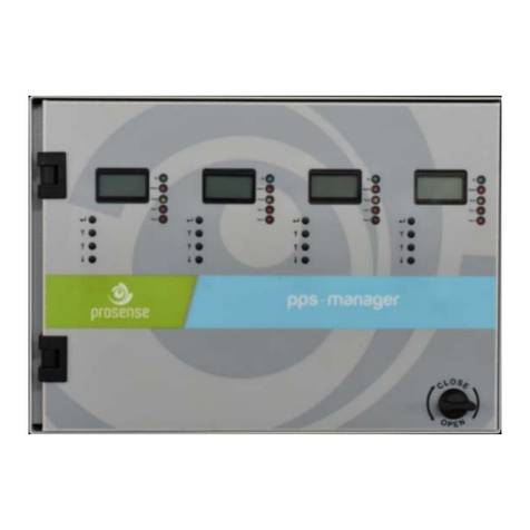
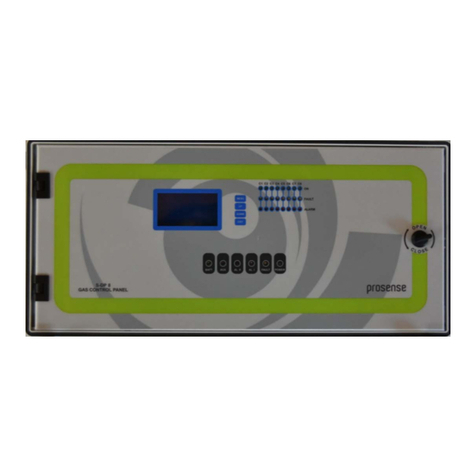
Prosense DPX Series User manual

2
PRS-UM-DP-X-EN-Rev1.0-17.11.2021
WARNING!
READ THIS INSTRUCTION FIRST!
This manual must be carefully read by all persons who have or will have the
responsibility for installing, using or servicing this product.
Like any equipment, this product will perform as designed only if installed,
used and serviced in accordance with the manufacturer’s instructions.
Otherwise, it could fail to perform as designed and persons who rely on this
product for their safety could suffer severe personal injury or death.
The warranties made by Prosense with respect to this product are voided if
the product is not installed, used and serviced in accordance with the
instructions in this user guide. Please protect yourself and other by following
them.
WARNING!
Inductive or capacitive loads like motors, ventilation, e.g. should not be
directly connected to the panel directly. In such cases, auxiliary external
relays should be use to drive these loads.

3
PRS-UM-DP-X-EN-Rev1.0-17.11.2021
Contents
1 Introduction..................................................................................................................................... 5
2 Technical Specifications................................................................................................................... 6
3 Panel Dimensions ............................................................................................................................ 7
4 Installation....................................................................................................................................... 8
5 Connections................................................................................................................................... 11
5.1 MODBUS and Siren Outputs:................................................................................................. 12
5.2 Analogue Channel Inputs: ..................................................................................................... 13
5.3 Relay Outputs ........................................................................................................................ 14
5.4 MODBUS Channel Inputs:...................................................................................................... 16
5.5 Power Inputs: ........................................................................................................................ 18
5.5.1 Main Power Connection................................................................................................ 19
5.5.2 Backup Battery Connection........................................................................................... 19
5.6 Fuses...................................................................................................................................... 20
5.7 Analogue Input Module......................................................................................................... 20
6 Indicators....................................................................................................................................... 22
6.1 Display: .................................................................................................................................. 23
6.2 Special States......................................................................................................................... 25
6.3 Warm-up Status: ................................................................................................................... 25
6.4 Fault Status:........................................................................................................................... 26
6.5 Overrange Status:.................................................................................................................. 26
6.6 Alarm Status: ......................................................................................................................... 27
7 Programming................................................................................................................................. 28
7.1 Panel Configuration:.............................................................................................................. 29
7.1.1 Setting Up Network Parameters: .................................................................................. 29
7.1.2 Setting Up Passwords:................................................................................................... 30
7.1.3 Setting Up Date and Time: ............................................................................................ 31
7.1.4 Setting Up Language:..................................................................................................... 31
7.1.5 Setting Up Battery: ........................................................................................................ 32
7.2 Detector Settings:.................................................................................................................. 32
7.2.1 Analogue Detector Configuration: ................................................................................ 32
7.2.2 Analogue Detector Alarm Settings:............................................................................... 35
7.2.3 4-20mA Settings: ........................................................................................................... 36
7.2.4 MODBUS Detector Configuration:................................................................................. 37
7.2.5 MODBUS Detector Alarm Settings: ............................................................................... 38
7.2.6 MODBUS Detector Calibration: ..................................................................................... 39
7.3 Relay Settings: ....................................................................................................................... 41
7.4 Test Options: ......................................................................................................................... 42
7.5 Information: .......................................................................................................................... 43
7.6 Resetting Alarms: .................................................................................................................. 45

4
PRS-UM-DP-X-EN-Rev1.0-17.11.2021
7.7 What to Do In Case Of Alarm ................................................................................................ 46
7.8 Failure Codes: ........................................................................................................................ 47
8 Declaration .................................................................................................................................... 49
9 Appendix-A – Prosense Gas No Index ........................................................................................... 50
10 Warranty statement.................................................................................................................. 52
10.1 Exclusions .............................................................................................................................. 52
10.2 Warranty Limitation and Exclusion ....................................................................................... 52
10.3 Limitation of Liability............................................................................................................. 52

5
PRS-UM-DP-X-EN-Rev1.0-17.11.2021
1Introduction
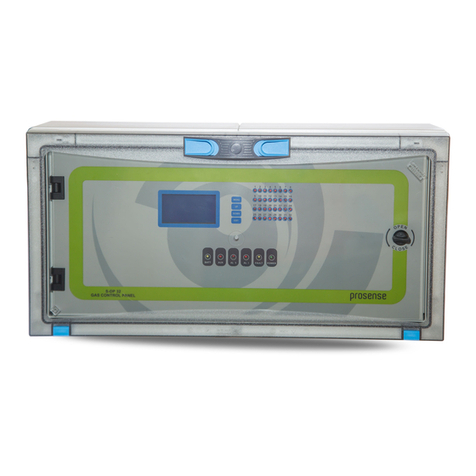
Prosense DPX Series Gas Control Panel is able to provide automatic gas concentration
reading and protection against gas explosions. The control panel is intended for the
continuous measurement and control of the gases present in the atmosphere. DPX Series
Gas Control Panel built as a wall mounted system. Panel permanently transmits the gas
concentration measurement from detectors and instantly handles the measurement of
detectors. The control panel is able to generate sound and visual alarm, when
measurements reach the programmed limit value.
Prosense DPX Series Control Panel has three levels of alarm which are adjustable according
to the measuring range and one fault alarm for the detection loop. Individual relays per
function ensure remote controlled output. There are 5 relays on the panel. Three of them
used as alarm relays and configured as ALARM-1, ALARM-2 and ALARM-3. There is one
FAULT relay to monitor overall fault status. An additional relay programmed for Overrange
can be optionally adjusted to alarm status.
Prosense DPX Series Panel is configured in 5 different configurations:
DPX4
4 x 4-20mA Analogue Channels
DPX8
8 x 4-20mA Analogue Channels
DPX32
32 x RS485 MODBUS RTU Detectors + 8 x 4-20mA Analogue Channels
DPX64
64 x RS485 MODBUS RTU Detectors + 8 x 4-20mA Analogue Channels
DPX128
128 x RS485 MODBUS RTU Detectors + 8 x 4-20mA Analogue Channels
Table 1: DPX Series Panel Models
DPX Series Gas Control Panel provides option for creating logical zones for independent
detectors to build similar infrastructure of the real detector location at panel side.
DPX Series Gas Control Panel has 128x64 OLED screen on the front panel to show status of
each detector. This screen and menu keys allow user to set correct properties for each
detector like gas concentrations by gas type, measurement type, measurement range and
alarm levels.
DPX Series Gas Control Panel complies to IEC 60079-0:2017 and IEC 60079-29-1:2016
standard requirements. Please refer to the certification label on the control panel to identify
the type of certification that relates to the product supplied.
Diagram 1:Panel Label
The model and serial number of the product given with “DP128/???????” numbers.

6
PRS-UM-DP-X-EN-Rev1.0-17.11.2021
2Technical Specifications
Power Source
220VAC
Power Consumption
27VDC/250mA - 6.75W max. (without connected detectors)
Inputs
DPX4 : 4 x Analogue input
DPX8 : 8 x Analogue input
DPX32 : 2 x MODBUS input (16 + 16) + 8 x Analogue input
DPX64 : 2 x MODBUS input (32 + 32) + 8 x Analogue input
DPX128 : 2 x MODBUS input (64 + 64) + 8 x Analogue input
Relay Outputs
FAULT, ALARM1, ALARM2, ALARM3, OVERRANGE (optional programmable
relay)
Contacts rating
3A, 24VDC
Display
Graphic OLED (128x64)
LED indicators
FAULT, ALARM1, ALARM2, ALARM2, OVERRANGE status LEDs for each zone
(40 LEDs)
Power/On, FAULT, ALARM1, ALARM2, ALARM3, SYS-FAULT LEDs for overall
monitoring
Audible indicators
Internal buzzer
Audible Output
Siren 24VDC/2A
Network Output
Ethernet-RJ45 / MODBUS over Ethernet (optional)
MODBUS Output
RS485 MODBUS RTU Output for external device communication
Backup battery
2 x 12V 7A/h (Optional)
Operating Temp.
-10 : 60
0
C
Humidity
15 - 95% non condensing
Housing
ABS IP66 (546 X 276 X 186 mm)
Weight
DPX4: 4kg
DPX8, DPX32, DPX64, DPX128: 6kg
Main power fuse
2A
Backup battery fuse
2A
Warm-up time
Up to 2 minutes
Delay time
Panel can recognize any special state in 2 minutes
Special States
Fault (Fault Relay is de-energised)
Alarm (Alarm Relays are energised)
Overrange (Overrange Relay is energised)
EMC conformity
EN 61326-1 Group-1 Class-A
IEC conformity
IEC 60079-29-1:2106
ATEX conformity
IEP 21 ATEX 0883X
ATEX Label
[Ex Gb] IIC
Program Release
V3.02.1.03
Special condition
Do NOT install in hazardous area
Event log
Up to 500 records
Clock battery
RTC 3V/10mA
Table 2: Technical specifications

7
PRS-UM-DP-X-EN-Rev1.0-17.11.2021
3Panel Dimensions
Panel dimensions are different for DPX4 and other models. DPX4 panel dimensions are
explained in Diagram-2:
Diagram 2: Dimensions (mm)
DPX8, DPX32, DPX64, DPX128 Panel dimensions are explained in Diagram 3:
Diagram 3: Dimensions (mm)

8
PRS-UM-DP-X-EN-Rev1.0-17.11.2021
4Installation
The DPX Series Gas Control Panel should never be placed in an explosive atmosphere and
should be readily accessible. It is necessary to drill holes for cable glands either on the top or
bottom of the control unit, depending on which side the electric cables are running in.
Before drilling any holes you can unscrew and remove the electronic parts to avoid
accidentally damaging it. DPX Series Gas Control Panel should not be placed nearby high
voltage cables or power cable, coaxial cables or transmitters, welding stations or frequency
regulators.
DPX Series Gas Control Panel box produced based on IP66 standard specifications. Always
use the screw holes to mount it and do not pierce panel from any other side. Always use
cable glands to make cable entries.
S-DPX4 panel has 4 plastic screws keeping panel door in place in front of panel. Use a flat
screwdriver to lose them and remove the panel door assembly. Please take care and remove
the connectors on the electronic card while removing the cover. Fix the panel on to the wall
via using 4 screw holes in each corner after removing the front cover. M4 screws are suitable
to fix the panel body to the wall. Once wall mounting completed reattached the front cover
and tighten 6 plastic screws.
Diagram 4: Panel cover plastic screw
To prepare cable entries, remove plastic cover from top or bottom on the panel. Then drill
the holes for cable entry and install cable glands to the holes you made it. Make sure you are
using an adequate IP66 rate cable gland to assure the box ingress protection is not
compromised. The panel box is modular and can be used with different assemblies. Prosense
recommends having cable entries from the lower side. Electronic board is located in the
front cover of the panel. The power supply is located at the back of panel box. The power
must be connected to this power supply. If the installation requires the connection to a
backup battery, place the battery to lover right side of the panel inside.
Plastic screws
Plastic screws

9
PRS-UM-DP-X-EN-Rev1.0-17.11.2021
Diagram 5: Panel body
DPX8, DPX32, DPX64, DPX128 panel has 6 plastic screws on the front of panel. Use a flat
screwdriver to lose them and remove the cover part on the front. Please take care and
remove the connectors on the electronic card while removing the cover. Fix the panel on the
wall via using 6 screw holes after removing the front cover. Reattached the front cover and
tighten 6 plastic screws when wall mounting completed.
To prepare cable entries, remove plastic covers from top or bottom on the panel. Then drill
the holes for cable entry and install cable glands to the holes you made it. Make sure you are
using an adequate IP66 rate cable gland to assure the box ingress protection is not
compromised. The panel box is modular and can be used with different assemblies. Prosense
recommends having cable entries from the lower side. Electronic board is located in the
front cover of the panel. The power supply is located at the back of panel box. The power
must be connected to this power supply. If the installation requires the connection to a
backup battery, place the battery to lover right side of the panel inside.
Backup battery connectors and fuse
Wall mounting hole
Power supply
N L G V-V+
Wall mounting hole
Wall mounting hole
Wall mounting hole
Main power entry and fuse
Space for backup
batteries
Power supply LED
Power supply output
adjustment switch

10
PRS-UM-DP-X-EN-Rev1.0-17.11.2021
Diagram 6: Panel cover plastic screw
Diagram 7: Panel body
Plastic screws
Backup battery connectors and fuse
Power supply
N L G V-V+
Wall mounting hole
Wall mounting hole
Main power entry and fuse
Space for backup batteries
Power supply output adjustment switch
Wall mounting hole
Plastic screws

11
PRS-UM-DP-X-EN-Rev1.0-17.11.2021
5Connections
DPX Series Gas Control Panel connections must be done on main board.
The main building blocks of the panel PCB are pointed with letters on picture. Their meaning
and details are as follows:
A
MODBUS and Siren Outputs
B
Analogue Channel Inputs
C
Relay Outputs
D
MODBUS Channel Inputs
E
Power Inputs
F
Ethernet Output (Optional)
Table 3: Main board sections
Diagram 8: Control panel main board
A
B
C
D
E
F

12
PRS-UM-DP-X-EN-Rev1.0-17.11.2021
5.1 MODBUS and Siren Outputs:
DPX Series Gas Control Panel provides RS485 MODBUS interface to communicate external
devices or computers. Prosense Panel Monitor Software can be used to configure panel
parameters and monitor the panel status through MODBUS communication. This Interface is
marked as RS485-3 on main PCB board.
Diagram 9: Control panel Modbus and Siren outputs
The Siren output provides 24VDC output to drive a sounder device. If panel is in normal
condition it does not provide power. It only provides power when power went in to fault or
alarm status. In case of alarm or fault user can disable this output temporarily via pressing
the MENU button. Panel waits five minutes and perform control again. If there is still alarm
or fault condition on panel it automatically activates output again to generate audible alarm.
Panel itself has also a buzzer on main board. Siren output is specially designed to provide
external audible alarm.
1K resistor should be placed between V + and V- pins of the SIREN1 port to the external siren
output. Otherwise, the panel will not be able to check the port status, so it will set an error
for this port. In case there is more than one sounder, 1K resistor should be added to the last
siren output
.
GND
A
B
MODBUS Output
V+
V-
Siren Output
2A Fuse for Siren Output

13
PRS-UM-DP-X-EN-Rev1.0-17.11.2021
5.2 Analogue Channel Inputs:
DPX series Gas Control Panel has analogue channel inputs to connect detectors via using
4-20mA output. DPX4 Panel has 4 analogue channel inputs while DPX8 Panel will have 8
analogue channel inputs.
Diagram 10: Analogue Channel Inputs
Panel must be connected to detectors through V+, V-(GND) and S via using three-wire cable.
Panel channels supply 24VDC power to detector and read the output signal of detector from
S port. Thus connections should be made correctly to do not cause any damage on the
detectors. Detector connections should be made with 3 core cable and pin definitions are as
follows:
Detector Pin
Panel pin
Meaning
S
S
4-20mA signal
V-
GND
GND (V-)
V+
V+
Supply (V+)
Table 4: Connection pin definitions
A sample connection schema is shown in below figure:
Diagram 11: Panel – Detector 4-20mA connection
DP4 Panel 4x Inputs:
CH1, CH2, CH3,CH4
DP8 Panel 8x Inputs:
CH1, CH2, CH3,CH4
CH5, Ch6,CH7,CH8
Ground

14
PRS-UM-DP-X-EN-Rev1.0-17.11.2021
Detectors should be connected with three-wire 1.5mm2cross section cable. Cable diameter
will be increased while distance increase between the panel and detectors. Recommended
cable types per distance are given in table 6:
Cable size
Cable type
Cable resistance
Maximum Cable length (L)
(cross sectional area)
nearest equivalent
Ω/km
Meters
0.5mm2
20AWG
36.8 Ω/km
400
1.0mm2
17AWG
19.5 Ω/km
750
1.5mm2
16AWG
12.7 Ω/km
1000
2.0mm2
14AWG
10.1 Ω/km
1250
2.5mm2
13AWG
8.0 Ω/km
1500
Table 5: Typical cable details and maximum distance for cabling
The use of industrial grade, suitably shielded field cable is recommended. The best
practices shown that, screened 3 cores (plus screen 90% coverage), suitably mechanically
protected copper cable with a suitable explosion-proof gland, or ¾” NPT steel conduit,
depending on the distance between signal received or control panel and detector 0.5 to 2.5
mm2 (20 to 13 AWG) conductors can give better results. Ensure the cable gland is installed
correctly and fully tightened.
5.3 Relay Outputs
DPX Series Gas Control Panel without any optional relay modules has five relay outputs
which are FAULT, ALARM1, ALARM2, ALARM3 and OVERRANGE. The connection ports are
marked on mainboard.
Diagram 12: Relay Outputs
Relay contacts can be adjusted as normally Open or Normally Close. Mainboard has 3 pins
for each relay to select relay contact mode via changing the jumper position:
NC : Normally closed contact pin (Select by jumper under relay)
NO : Normally open pin (Select by jumper under relay)
NO/NC setting pins

15
PRS-UM-DP-X-EN-Rev1.0-17.11.2021
The relay output pin positions shown below:
Table 6: Relay output pin positions
Fault Relay is always works in Normally Close mode and there is no selection pin for fault
relay (Relay-1). If panel lost power user will always get switching contact from fault relay.
Relay numbers and related events are defined as below:
Relay No
Event
Monitoring area
Assignment
Relay-1
FAULT
All Zones and Panel itself
No alteration
Relay-2
ALARM-1
All Zones
No alteration
Relay-3
ALARM-2
All Zones
No alteration
Relay-4
ALARM-3
All Zones
No alteration
Relay-5
OVERRANGE
All Zones
Can be altered
Table 7: Relay assignments
Relay activation rules are as follows:
FAULT (RELAY-1): This relay will be activated when any of the detectors in the system is in
fault status.
ALARM1 (RELAY-2): This relay will be activated when any of the detectors in the system will
exceed the programmed AL1 level.
ALARM2 (RELAY-3): This relay will be activated when any of the detectors in the system will
exceed the programmed AL2 level.
ALARM3 (RELAY-4): This relay will be activated when any of the detectors in the system will
exceed the programmed AL3 level.
OVERRANGE (RELAY-5): This relay will be activated when any of the detectors in the system
will exceed the defined measurement level.
Not: Relays should not be connected directly to devices using high current. The relay outputs
should be used as control signal. In order to drive high load devices external relays should be
used and panel relay outputs must be used to drive external relays.
Normally Open (NO)
Normally Close (NC)

16
PRS-UM-DP-X-EN-Rev1.0-17.11.2021
5.4 MODBUS Channel Inputs:
DPX Series Gas Control Panel has two MODBUS channel input ports on main board:
Diagram 13: MODBUS Channel Inputs
MODBUS Channel pin details are given in table XX:
Socket Label
SW name
Pins
Pin definitons
RS485-A MODBUS Line 1
GND
Ground for MODBUS connection
A
A Line for MODBUS communication
B
B Line for MODBUS communication
VOUT-A Power Output Line 1
+
V+ to supply detector power on Line 1
-
V- to supply detector power on Line 1
RS485-B MODBUS Line 1
GND
Ground for MODBUS connection
A
A Line for MODBUS communication
B
B Line for MODBUS communication
VOUT-B Power Output Line 2
+
V+ to supply detector power on Line 2
-
V- to supply detector power on Line 3
Table 8: MODBUS Channel pin definitions
DPX Series Gas Control Panel is a master device in the MODBUS Network and it initiates the
communication with a “query” to “Slave” devices which are detectors. The “Slave “ which is
constantly monitoring the network for “Queries” will recognise only the “Queries” addressed
to it and will respond by returning a “response”. The connection topology will be as follows:
Diagram 14: MODBUS Communication

17
PRS-UM-DP-X-EN-Rev1.0-17.11.2021
DPX Series Gas Control Panel can monitor detectors via RS485 serial connection. It can also
provide power for detectors. V+, V-(GND), A and B ports must be connected via using four-
wire cable. Detector connections supply 27VDC power to detector and read the output
signal of detector from A and B ports. Thus connections should be made correctly to do not
cause any damage on the detectors. Detector power connection should be done with
1.5mm2cross section cable. The total distance between control panel and detectors should
not exceed 800 meters. Detector connections should be made with 4 core cable wire that 2
for power and 2 for RS485 and pin definitions are as follows:
Port
Type
Usage
V+
output
+24VDC to provide power for detector
V-
output
-VDC to provide power for detector
A
input
RS485 port A
B
input
RS485 port B
Table 9: Connection pin definitions
The wiring for detectors utilized with RS485 board should be done by using connection cable
EIA RS485 2 core wires with section 0.22 / 0.35 mm2 and shielded. Nominal capacity
between the wires should be < 50pF/m and nominal impedance should be 120 Ohms.
The V+, V- ports and A, B ports are located different sockets in DPX Series Gas Control Panel
main board. These ports are also formed in different sockets on Prosense detectors. The
connections should be done with care to do not mix power and RS485 ports. All detectors
will be connected through one cable via hopping one detector to another till the last
detector on the line. The connection schema is given in Diagram 11:
Diagram 15: Panel to detector connections
The connection must have bus structure (daisy-chain) as given in above diagram16. Star
topology should not be used. Also devices cannot be used with mixed connection.
B AV- V+
A
B
V+
V-
DP Series Panel
B A V-V+
V+
V-
A
B
Detector 1
Detector 2

18
PRS-UM-DP-X-EN-Rev1.0-17.11.2021
Diagram 16: MODBUS detector connections
Each detector connected to same DPX Series Gas Control Panel should have unique address.
Detectors having same address would not be recognised by control panel. The last detector
at the RS485 serial line should have the end of line resistor to enable the total
communication line. Otherwise control panel may not communicate to all, some or none of
the detectors.
5.5 Power Inputs:
DPX series Gas Control Panel has internal switching power supply. The connections between
switching power supply and main board is already done in factory. The battery connections
are already provided as ready to connect for user. The connection pins are marked on
mainboard:
Diagram 17: Power Inputs
Star connection - Wrong
Mixed connection - Wrong
Main Power In
V+
V-
Backup Battery Power In
V+
V-
Backup Battery Operation button
Daisy Chain Connection - Correct

19
PRS-UM-DP-X-EN-Rev1.0-17.11.2021
There is no need to remove the power and grounding connections from panel mainboard.
But in case of any service action pins and connection locations must be controlled according
to labels printed on mainboard.
5.5.1 Main Power Connection
The Panel has internal switching power supply to mains connection (220VAC). This
connection must be made three-wire 1.5mm2cross section cable to the main supply
terminal entries and fixed by using cable fastener on the terminal. Make sure all the
detectors connected properly before applying the power. The power supply pin labels and
their definitions are given in table10:
Name
Type
Usage
L
input
Phase
Gnd
input
Ground
N
input
Neutral
V+
output
+24VDC (Only for panel and detectors, do not use for any other device)
V-
output
-VDC
Table 10: Main power connection details
5.5.2 Backup Battery Connection
To continue operation in case of main power failure two backup batteries (12V 7Ah) must be
serially connected to the system. Take extra care to connect the batteries with correct poles.
The cables or main board can be damaged in case of mixing pins or making short circuits.
Backup batteries must be connected as shown below.
Diagram 18: Backup battery connection
Panel will automatically switch working with battery power in case of mains loss. If panel
was off when mains power is not available user must press the battery operation button to
start the panel via using backup battery power.
Panel battery input
V+
V-
V+
V-
Battery 1/ 12V 7Ah
Battery 2/ 12V 7Ah
V-
V+

20
PRS-UM-DP-X-EN-Rev1.0-17.11.2021
5.6 Fuses
DPX series Gas Control Panel has six fuses on main board to keep connected devices and
panel safe. Their names and details are given below:
Fuse
Rating
Usage
F1
2A
Main power protection
F2
2A
VOUT A Protection
F3
2A
VOUT B Protection
F4
2a
Analog channel power protection
F5
2A
Battery protection
F6
2A
Siren (sounder) power protection
Table 11: Main board Fuse details
5.7 Analogue Input Module
Prosense provides analogue input module to connect analogue output detectors to panel.
The module has two input ports to connect analogue detectors and connects them as
Modbus detector. Module converts measurement signal coming from detectors to MODBUS
data and performs MODBUS communication with the panel. Detectors will be part of
MODBUS chain. Module needs power input to operate and must be connected to panel
MODBUS chain as similar to MODBUS detectors. The board details are given below:
Diagram 18: Analogue Module connections
S GND V+
Channel-1 Input
to connect first
analogue detector
Power and MODBUS
input ports to
connect DPX panel
S GND V+
Channel-2 Input to
connect second
analogue detector
Fault Alarm1 Alarm2
Relay Output ports
Status LEDs
Fault|On|Overrange|Alarm1|Alarm2
Alarm level adjustment switches
NO/NC pins
Fuse
This manual suits for next models
5
Table of contents
Other Prosense Control Panel manuals
Popular Control Panel manuals by other brands

Bender
Bender COMTRAXX CP305 manual

Endress+Hauser
Endress+Hauser Liquiline CM442 Brief operating instructions

GE Security
GE Security 1200C user manual

Clarion
Clarion CMRC1-BSS Owner's manual & installation guide

Trane
Trane Zone Panel installation guide

Ness
Ness M1 Cross Platform Control installation manual