protech prox KF-P230 User manual

USER
MANUAL
KF-P230
21.5" Multi-Functional
Kiosk System
KF-P230 M2

KF-P230
21.5” Multi-Functional
Kiosk System
COPYRIGHT NOTICE & TRADEMARK
All trademarks and registered trademarks mentioned herein are the
property of their respective owners.
This manual is copyrighted in Dec. 2021. You may not reproduce or
transmit in any form or by any means, electronic, or mechanical,
including photocopying and recording.
DISCLAIMER
This user’smanual is meant to assist users in installing and setting up
the system. The information contained in this document is subject to
change without any notice.
CE NOTICE
This is a class A product. In a domestic environment this product may
cause radio interference in which case the user may be required totake
adequate measures.

FCC NOTICE
This equipment has been tested and found to comply with the limits for
a Class A digital device, pursuant to part 15 of the FCC Rules. These
limits are designed to provide reasonable protection against harmful
interference when the equipment is operated in a commercial
environment. This equipment generates, uses, and can radiate radio
frequency energy and, if not installed and used in accordance with the
instruction manual, may cause harmful interference to radio
communications. Operation of this equipment in a residential area is
likely to cause harmful interference in which case the user will be
required to correct the interference at his own expense.
You are cautioned that any change or modifications to the equipment
not expressly approve by the party responsible for compliance could
void your authority to operate such equipment.
CAUTION: Danger of explosion may occur when the battery
is incorrectly replaced. Replace the battery
only with the
same or equivalent type recommended by the manufacturer.
Dispose of used batteries according to the manufacturer’s
instructions.
WARNING: Some internal parts of the system may have
high electrical voltage. We strongly recommend that only
qualified engineers are allowed to service and disassemble
the system. If any damages should occur on the system and
are caused by unauthorized servicing, it will not be covered
by the product warranty. Please operate the LCD and
Touchscreen with extra care as they can break easily.

i
Contents
Revision History ............................................................................................ vi
1Introduction ........................................................................................... 1-1
1.1 About This Manual ..................................................................... 1-2
2Getting Started ...................................................................................... 2-1
2.1 Package List............................................................................... 2-2
2.2 System Overview ....................................................................... 2-3
2.3 Quick Setup................................................................................ 2-7
2.3.1 Turning On and Connecting KF-P230 to Network .............. 2-7
2.3.2 Installing Printer Paper Roll ................................................ 2-8
2.4 System Specifications ................................................................ 2-9
2.5 Safety Precautions ................................................................... 2-10
3System Configuration............................................................................ 3-1
3.1 System I/O Ports Diagrams........................................................ 3-2
3.1.1 Panel PC Rear I/O Ports Diagram ...................................... 3-2
3.1.2 Kiosk System Rear I/O Ports Diagram ............................... 3-2
3.2 Main Board Component Locations & Jumper Settings .............. 3-3
3.3 How to Set Jumpers................................................................... 3-4
3.4 Connector & Jumper Quick Reference Table............................. 3-6
3.5 Panel PC I/O Ports ..................................................................... 3-8
3.5.1 PWR IN Connector ............................................................. 3-8
3.5.2 COM Ports (COM1, COM2, COM3, JCOM4_1) ................. 3-8
3.5.3 VGA Port (VGA) .................................................................. 3-9
3.5.4 LAN Port (LAN) ................................................................. 3-10
3.5.5 HDMI Port Connector (HDMI)........................................... 3-11

ii
3.5.6 USB 3.0 Connector (USB1) ..............................................3-12
3.5.7 USB 2.0 Connector (USB2) ..............................................3-13
3.6 Setting Connectors and Jumpers.............................................3-14
3.6.1 COM2, COM3 Voltage Selection (JP_COM2, JP_COM3)3-14
3.6.2 COM Connectors (JCOM2_1, COM3_1, JCOM4_1)........ 3-15
3.6.3 COM4 Port and iButton Selection (JP4, JP5, JP6)........... 3-15
3.6.4 SPI (BIOS) Flash Wafer (JP13) ........................................ 3-16
3.6.5 USB Connectors (JUSB4, JUSB6, JUSB7, JUSB8, JUSB910)
.......................................................................................... 3-17
3.6.6 USB 2.0 Port / On Board Touch Selection (JP18, JP14) ..3-19
3.6.7 USB4 / M.2_E (Wi-Fi) Selection (JP20, JP15) ................. 3-20
3.6.8 Power for 2nd Display Connector (JVOUT_12V) ............. 3-20
3.6.9 Power for Thermal Printer Connector (JVOUT_24V) ....... 3-21
3.6.10 Fan Connector (CPU_FAN1) ............................................ 3-21
3.6.11 PS/2 Keyboard function for MSR Device (JPS2).............. 3-22
3.6.12 Audio Connector (JAUDIO1) ............................................3-22
3.6.13 Speaker Connector (JSPK1) ............................................ 3-23
3.6.14 System LED Wafer (JSYS_LED1) ....................................3-23
3.6.15 Power Switch Wafer (JPWR_SW) .................................... 3-23
3.6.16 System Reset Wafer (JP19) ............................................. 3-24
3.6.17 I2C Wafer (JI2C1) .............................................................3-24
3.6.18 RTC Coin Battery Wafer (JBAT1) .....................................3-24
3.6.19 Clear RTC Data Selection (JRTC1).................................. 3-25
3.6.20 Clear CMOS Data Selection (JCMOS1) ........................... 3-25
3.6.21 Unlock the Entire SPI Flash (override descriptor setting) (JP1)
...................................................................................... 3-26
3.6.22 SATA 3.0 Connector (SATA1) ........................................... 3-26
3.6.23 LVDS Connector (JLVDS1)............................................... 3-27
3.6.24 Inverter Connector (JINV1)............................................... 3-28
3.6.25 HDD Power Port (JHDD_PWR1)...................................... 3-28

iii
3.6.26 LVDS Resolution Selection (JP7, JP8) ............................. 3-29
3.6.27 LVDS VCC Selection (JP11) ............................................. 3-30
3.6.28 LVDS Backlight Control Selection (JP12) ......................... 3-31
3.6.29 M.2 M-Key Connector for SSD (M2_M)............................3-32
3.6.30 M.2 E-Key Connector for Wi-Fi (M2_E) ............................ 3-33
3.6.31 On Board Touch Wafer (JTOUCH1) ................................. 3-34
3.6.32 Flash MCU Firmware Wafer (JMCU)................................ 3-34
4Software Utilities ................................................................................... 4-1
4.1 Introduction................................................................................. 4-2
4.1.1 Installing Intel®Chipset Software Installation Utility ........... 4-4
4.1.2 Intel®Management Engine Components Installer Installation
............................................................................................ 4-5
4.1.3 Installing Microsoft Hotfix Driver installation ....................... 4-6
4.1.4 Installing Graphics Driver Utility.......................................... 4-7
4.1.5 Installing LAN Driver Utility ................................................. 4-8
4.1.6 Installing Sound Driver Utility.............................................. 4-9
4.1.7 Installing Intel®Serial I/O Driver Utility.............................. 4-10
5BIOS SETUP......................................................................................... 5-1
5.1 Introduction................................................................................. 5-2
5.1.1.1 Accessing Setup Utility ................................................... 5-4
5.1.2 Main .................................................................................... 5-7
5.1.3 Advanced ............................................................................ 5-8
5.1.3.1 Advanced - CPU Configuration..................................... 5-10
5.1.3.2 Advanced - SATA Configuration.................................... 5-12
5.1.3.3 Advanced – Intel(R) Rapid Storage Technology........... 5-13
5.1.3.4 Advanced - PCH-FW Configuration.............................. 5-14
5.1.3.5 Advanced - Trusted Computing .................................... 5-15
5.1.3.6 Advanced - ACPI Settings ............................................ 5-17
5.1.3.7 Advanced - F81866 Super IO Configuration ................5-18

iv
5.1.3.8 Advanced - Hardware Monitor ...................................... 5-25
5.1.3.9 Advanced - F81866 Watchdog ..................................... 5-27
5.1.3.10 Advanced - USB Configuration ..................................... 5-28
5.1.3.11 Advanced - Network Stack Configuration ..................... 5-29
5.1.4 Chipset .............................................................................. 5-31
5.1.4.1 System Agent (SA) Configuration .................................5-32
5.1.4.2 PCH IO Configuration ................................................... 5-34
5.1.5 Security ............................................................................. 5-36
5.1.6 Boot...................................................................................5-38
5.1.7 Save & Exit ....................................................................... 5-40
Appendix A System Diagrams .......................................................A-1
KF-P230 System Assembly Exploded Diagram .......................................A-2
KF-P230 System Body Assembly Exploded Diagram (1) ........................A-3
KF-P230 System Body Assembly Exploded Diagram (2) ........................A-4
KF-P230 System Body Assembly Exploded Diagram (3) ........................A-5
KF-P230 System Body Assembly Exploded Diagram (4) ........................A-6
KF-P230 System Body Assembly Exploded Diagram (5) ........................A-7
KF-P230 System Body Assembly Exploded Diagram (6-1) .....................A-9
KF-P230 System Body Assembly Exploded Diagram (6-2) ...................A-10
KF-P230 System Body Assembly Exploded Diagram (6-3) ...................A-11
KF-P230 System Body Assembly Exploded Diagram (6-4) ...................A-12
KF-P230 Upper Door Assembly Exploded Diagram (1) .........................A-13
KF-P230 Upper Door Assembly Exploded Diagram (2) .........................A-14
KF-P230 Upper Door Assembly Exploded Diagram (3) .........................A-15
KF-P230 Upper Door Assembly Exploded Diagram (4-1)......................A-18
KF-P230 Upper Door Assembly Exploded Diagram (4-2)......................A-19
KF-P230 Lower Door Assembly Exploded Diagram (1) .........................A-20
KF-P230 Lower Door Assembly Exploded Diagram (2) .........................A-21

v
Appendix B Technical Summary ................................................B-1
Interrupt Map............................................................................................B-2
I/O MAP ..................................................................................................B-17
Memory Map...........................................................................................B-20
Configuring WatchDog Timer .................................................................B-22
Flash BIOS Update.................................................................................B-24

vi
Revision History
The revision history of KF-P230 User Manual is described below:
Version No.
Revision History
Date
M2
In Section 2.5 Safety Precautions, added the
caution message: “The equipment power supply
cord shall be connected to a socket-outlet with
earthing connection.” on Page 2-10.
2021/12/02
M1
Initial Release
2021/04/26

KF-P230 SERIES USER MANUAL
Page: 1-1
1 Introduction
This chapter provides the introduction for KF-P230 system
as well as the framework of the user manual.
The following topic is included:
•About This Manual

Chapter 1 Introduction
KF-P230 SERIES USER MANUAL
Page: 1-2
1.1 About This Manual
Thank you for purchasing our KF-P230 system. The KF-P230 is an updated system
designed to be comparable with the highest performance of IBM AT personal
computers. The KF-P230 provides faster processing speed, greater expandability and
can handle more tasks than before. This manual is designed to assist you how to
install and set up the whole system. It contains 5 chapters and 2 appendixes. Users can
configure the system according to their own needs. This user manual is intended for
service personnel with strong hardware background. It is not intended for general
users.
The following section describes the structure of this user manual.
Chapter 1 Introduction
This chapter introduces the framework of this user manual.
Chapter 2 Getting Started
This chapter describes the package contents and system specifications, and illustrates
the physical appearances for KF-P230 system. Read the safety reminders carefully on
how to take care of your system properly.
Chapter 3 System Configuration
This chapter describes the locations and functions of the system main board
components. You will learn how to properly configure the connectors and system
configuration jumpers on the main board and configure the system to meet your own
needs.
Chapter 4 Software Utilities
This chapter introduces how to install Intel Chipset Software Installation Utility, Intel
Management Engine Components Installer Driver Utility, Microsoft Hotfix Driver
Utility, Graphics Driver Utility, LAN Driver Utility, Sound Driver Utility and Serial
IO Driver Utility.
Chapter 5 AMI BIOS Setup
This chapter provides BIOS setup information.
Appendix A System Diagrams
This appendix provides the easy maintenance and exploded diagrams and part
numbers of KF-P230.
Appendix B Technical Summary
This appendix provides the information about the system block diagram, allocation
maps for system resources, Watchdog Timer Configuration and Flash BIOS Update.

KF-P230 Series User Manual
Page: 2-1
2 Getting Started
This chapter provides the introduction for the KF-P230
system as well as the framework of the user manual.
The following topic is included:
•Package List
•Kiosk System Overview
•System Specifications
•Quick Setup
•Safety Precautions
Experienced users can jump to Chapter 3 on page 3-1
for a quick start.

Chapter 2 Getting Started
KF-P230 Series User Manual
Page: 2-2
2.1 Package List
If you discover any of the items listed below are damaged or lost, please contact
your local distributor immediately.
Item
Q’ty
KF-P230 Kiosk System
1
Quick Guide
1
Manual/Driver DVD
1
Door Key
2

Chapter 2 Getting Started
KF-P230 Series User Manual
Page: 2-3
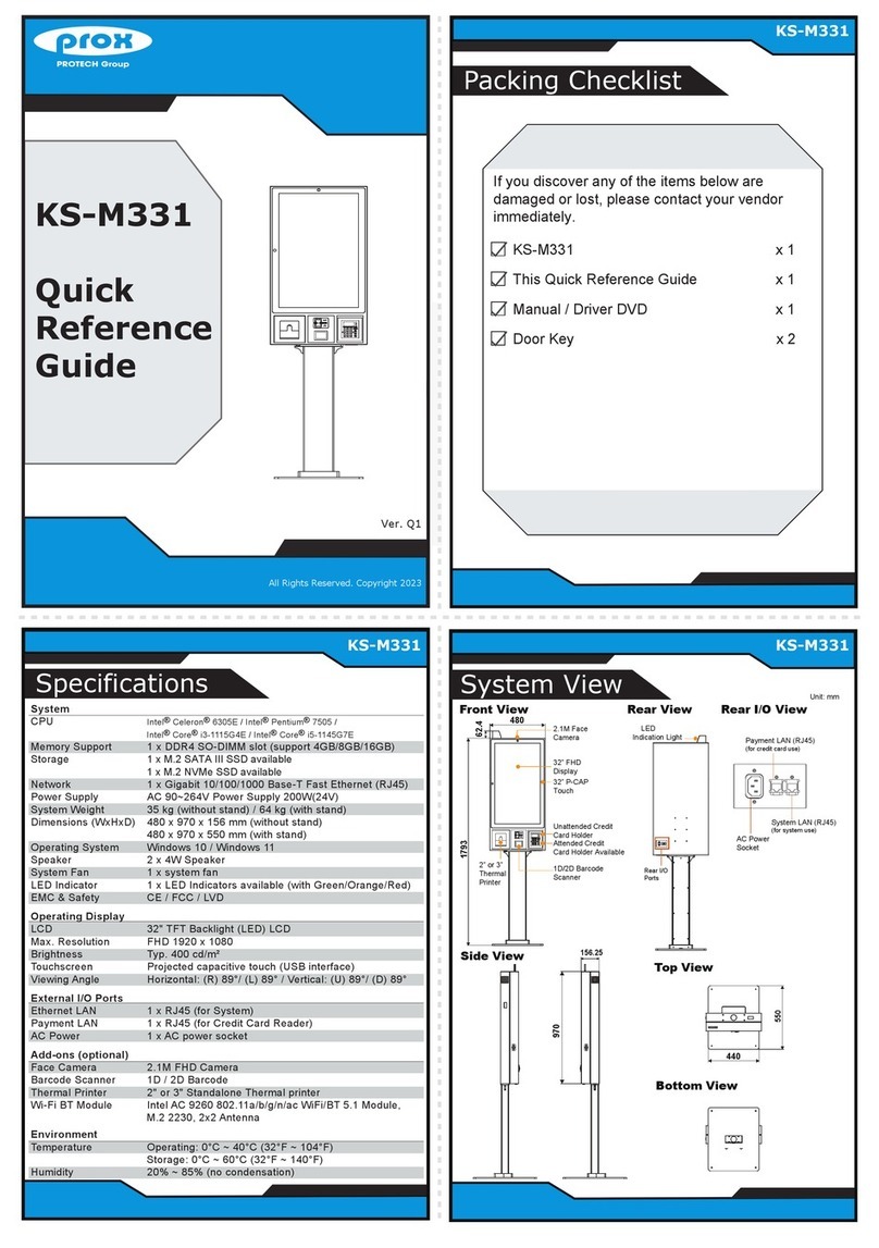
2.2 System Overview
Unit: mm
Front View
1070
904.35
895
1279
1378
1625
452
543.60
Face Camera
Barcode Scanner
Coin Acceptor
Credit Card Reader
IC Card Reader
Bill Acceptor
21.5” Touch Panel
Return
(with Printer)
Stand

Chapter 2 Getting Started
KF-P230 Series User Manual
Page: 2-4
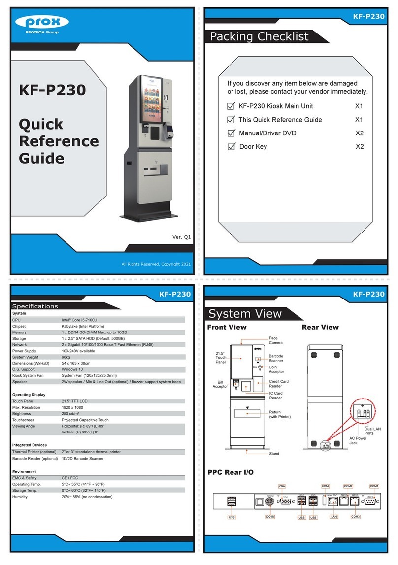
Rear View
AC Power
Jack
Dual LAN
Ports

Chapter 2 Getting Started
KF-P230 Series User Manual
Page: 2-5
Side View
Unit: mm
380
273.10

Chapter 2 Getting Started
KF-P230 Series User Manual
Page: 2-6
Top View
Unit: mm
Bottom View
689.69
479.15

Chapter 2 Getting Started
KF-P230 Series User Manual
Page: 2-7
2.3 Quick Setup
2.3.1 Turning On and Connecting KF-P230 to Network
Step 1. From the lower bottom on the rear of the system, connect the AC
power cord to the AC power jack and connect the Ethernet cables
to the dual LAN ports.
Step 2. After the I/O ports are all connected properly, attach the I/O panel
cover bracket onto the I/O ports panel compartment and secure
it with the M3 screw.
AC Power Jack
Dual LAN
Ports
KF-P230 I/O Ports

Chapter 2 Getting Started
KF-P230 Series User Manual
Page: 2-8
2.3.2 Installing Printer Paper Roll
Step 1. Insert the key to unlock the Printer Door.
Step 2. Open up the printer door from the top side.
Step 3. Press the printer door latch located on the upper-right of the Printer
to release.
Step 4. Pull out a small paper slip from the start of the paper roll and drop
the paper roll into the thermal printer.
Step 5. Close the cover of Thermal Printer and the Kiosk Printer Door and
lock it up with the key to complete.
Note: The starting paper slip must be positioned on top of the paper roll before you drop it into the
printer.
KF-P230 Thermal Printer

Chapter 2 Getting Started
KF-P230 Series User Manual
Page: 2-9
2.4 System Specifications
System
CPU
Intel®Core™ i3-7100U
Chipset
Kaby Lake (Intel Platform)
Memory
1 x DDR4 SO-DIMM (max. up to 16GB)
Storage
1 x 2.5" SATA HDD (Default: 500GB)
Network
2 x Gigabit 10/100/1000 Base-T Fast Ethernet
(RJ45)
Power Supply
100-240V available
Speaker
2W speaker
Mic & Line Out (optional)
Buzzer support system beep
System Weight
98kg
Dimensions
54 x 163 x 38cm (W x H x D)
O.S. Support
Windows 10
Kiosk System Fan
System Fan (120x120x25.3mm)
Operating Display
Touch Panel
21.5” TFT LCD
Max. Resolution
1920 x 1080
Brightness
250 cd/m2
Touchscreen
Projected Capacitive Touch
Viewing Angle
Horizontal: (R) 89°/ (L) 89°
Vertical: (U) 89°/ (L) 8°
Integrated Devices
Thermal Printer (optional)
2" or 3" standalone thermal printer
Barcode Reader (optional)
1D/2D Barcode Scanner
Environment
EMC & Safety
CE / FCC
Operating Temp.
5°C ~ 35°C (41°F ~ 95°F)
Storage Temp.
0°C ~ 60°C (32°F ~ 140°F)
Humidity
20% ~ 85% (no condensation)
Other manuals for prox KF-P230
1
This manual suits for next models
1
Table of contents
Other protech Digital Signage manuals

protech
protech MD-591X User manual

protech
protech prox KS-M220 User manual

protech
protech prox KF-P230 User manual

protech
protech KF-7131 User manual

protech
protech prox SP-C085 User manual

protech
protech KF-7270 User manual

protech
protech KS-M331 User manual

protech
protech PA-1822 User manual

protech
protech prox KS-M220 User manual

protech
protech KS-1130 User manual