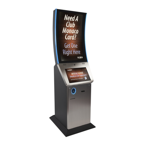
protech KF-7270 User manual

USER
MANUAL
KF-7270 M1
KF-7270
Hi-Life Self-Service Kiosk System

KF-7270 Self-Service Kiosk
with P-Cap Touch
COPYRIGHT NOTICE & TRADEMARK
All trademarks and registered trademarks mentioned herein are the
property of their respective owners.
This manual is copyrighted in June 2018. You may not reproduce or
transmit in any form or by any means, electronic, or mechanical,
including photocopying and recording.
DISCLAIMER
This user’s manual is meant to assist users in installing and setting up
the system. The information contained in this document is subject to
change without any notice.
CE NOTICE
This is a class A product. In a domestic environment this product may
cause radio interference in which case the user may be required to take
adequate measures.

FCC NOTICE
This equipment has been tested and found to comply with the limits for
a Class A digital device, pursuant to part 15 of the FCC Rules. These
limits are designed to provide reasonable protection against harmful
interference when the equipment is operated in a commercial
environment. This equipment generates, uses, and can radiate radio
frequency energy and, if not installed and used in accordance with the
instruction manual, may cause harmful interference to radio
communications. Operation of this equipment in a residential area is
likely to cause harmful interference in which case the user will be
required to correct the interference at his own expense.
You are cautioned that any change or modifications to the equipment
not expressly approve by the party responsible for compliance could
void your authority to operate such equipment.
CAUTION: Danger of explosion may occur when the battery
is incorrectly replaced. Replace the battery
only with the
same or equivalent type recommended by the manufacturer.
Dispose of used batteries according to the manufacturer’s
instructions.
WARNING: Some internal parts of the system may have high
electrical voltage. We strongly recommend that only qualified
engineers are allowed to open and disassemble the system.
Please operate the LCD and Touchscreen with extra care as
they can be broken easily.

i
Contents
Revision History ........................................................................................... vii
1 Introduction ......................................................................................... 1-1
1.1 About This Manual ....................................................................... 1-2
2 Getting Started .................................................................................... 2-1
2.1 Package List ................................................................................ 2-2
2.3 System Overview ......................................................................... 2-3
2.3.1 Front View ............................................................................. 2-3
2.3.2 Rear View .............................................................................. 2-4
2.3.3 Side View .............................................................................. 2-5
2.3.4 Top View ................................................................................ 2-6
2.3.5 Bottom View .......................................................................... 2-6
2.3.6 Quarter View ......................................................................... 2-7
2.4 Acrylic Board View ....................................................................... 2-8
2.5 Panel View ................................................................................. 2-10
2.6 Life ET Logo, RFID Sensor Area and Text Design .................... 2-12
2.7 Turning On KF-7270 and Connecting System to Network ........ 2-15
2.8 System Specifications ................................................................ 2-18
2.9 Safety Precautions ..................................................................... 2-21
3 System Configuration......................................................................... 3-1
3.1 External System I/O Ports Diagram ............................................. 3-2
3.2 Internal Main Board Box I/O Ports Diagram ................................ 3-3

ii
3.3 Function Buttons and I/O Ports ................................................... 3-4
3.3.1 DC IN Port ............................................................................. 3-4
3.3.2 COM Ports & VGA Connector (COM1, COM_VGA, COM3,
COM3_1, COM4_1, COM5) .................................................. 3-4
3.3.3 LAN & USB Ports .................................................................. 3-7
3.3.4 USB 3.0 Connectors (eSATA, USB2, USB3) ........................ 3-8
3.3.5 2nd Display Power Port ......................................................... 3-9
3.4 Main Board Component Locations & Jumper Settings .............. 3-10
3.5 Jumper & Connector Quick Reference Table ............................ 3-13
3.6 Setting Jumpers ......................................................................... 3-15
3.7 Setting Main Board Connectors and Jumpers ........................... 3-17
3.7.1 COM Port RI & Voltage Selection (JP_COM1, JP_COM2,
JP_COM3, JP_COM4) ........................................................ 3-17
3.7.2 i-Button Connector (I-BUT) ................................................. 3-18
3.7.3 i-Buttion Function Selection (JP22, JP23, JP24) ................ 3-19
3.7.4 Internal USB 2.0 Connectors (USB6~8, USB9-1, USB4_1) ......
....................................................................................... 3-20
3.7.5 LED Connectors (PWR_LED, HDD_LED) .......................... 3-21
3.7.6 System Fan and CPU FAN Connectors (SYS_FAN1,
CPU_FAN1) ......................................................................... 3-22
3.7.7 Power Input Connector (PWR_IN1) .................................... 3-23
3.7.8 Power Connectors (DC24V, DC12V, DC5V) ....................... 3-24
3.7.9 Power Switch Connectors (SW1, SW2) .............................. 3-25
3.7.10 External Speaker Connectors (SPK1, SPK2) (option) ........ 3-26
3.7.11 Speaker Selection (JP13) ................................................... 3-27
3.7.12 Inverter Connector (JINV1) ................................................. 3-28
3.7.13 LVDS Connector (LVDS1) ................................................... 3-29
3.7.14 LVDS Panel Power Input Selection (JP25) ......................... 3-30

iii
3.7.15 LVDS Backlight Type Selection (JP26) ............................... 3-31
3.7.16 LVDS Backlight Control Selection (JP27) ........................... 3-31
3.7.17 LVDS Panel Sequence Selection (JP29) ............................ 3-32
3.7.18 MSR/Card Reader Connector (PS2_1) ............................... 3-33
3.7.19 SATA & SATA Power Connectors (SATA1, SATA2,
SATA_PWR1, SATA_PWR2) .............................................. 3-34
3.7.20 Touch Panel Connector (TOUCH1) ..................................... 3-35
3.7.21 Touch Panel & USB9-1 Selection (JP18, JP19) .................. 3-36
3.7.22 LVDS Output Resolution Selection (JP8 and JP9) ............. 3-37
3.7.23 Mini PCIe/mSATA Connector .............................................. 3-38
3.7.24 Mini PCIe and USB6 Selection (JP21) ................................ 3-39
3.7.25 Embedded DisplayPort (EDP) Connector (EDP) (option) ... 3-40
3.7.26 Configuration / Recovery Selection (JP11) ......................... 3-41
3.7.27 VCCIO / REFIN Selection (JP10) ........................................ 3-42
3.7.28 Clear CMOS Data Selection (JCMOS1) ............................. 3-43
3.7.29 GPIO Connector (GPIO1) ................................................... 3-44
3.7.30 Audio Jack (LINE-OUT1) .................................................... 3-44
4 Software Utilities ................................................................................. 4-1
4.1 Introduction .................................................................................. 4-2
4.2 Installing Intel® Chipset Software Installation Utility .................... 4-3
4.2.1 Introduction ............................................................................ 4-3
4.2.2 Intel® Chipset Software Installation Utility ............................. 4-3
4.3 Installing Graphics Driver Utility ................................................... 4-4
4.4 Installing LAN Driver Utility .......................................................... 4-5
4.5 Installing Sound Driver Utility ....................................................... 4-6
4.5.1 Installing Intel® Management Engine Components Installer . 4-7
4.5.2 Installing Microsoft Hotfix kb3211320 and kb3213986 Driver

iv
Utility ...................................................................................... 4-8
5 BIOS SETUP ........................................................................................ 5-1
5.1 Introduction .................................................................................. 5-2
5.2 Accessing Setup Utility ................................................................ 5-3
5.3 Main Menu ................................................................................... 5-6
5.4 Advanced ..................................................................................... 5-7
5.4.1 Advanced - CPU Configuration ............................................. 5-8
5.4.2 Advanced - SATA Configuration (AHCI Mode) .................... 5-10
5.4.3 Advanced - PCH-FW Configuration .................................... 5-12
5.4.4 Advanced - ACPI Settings ................................................... 5-13
5.4.5 Advanced - F81866 Super IO Configuration ....................... 5-14
5.4.6 Advanced - Hardware Monitor ............................................ 5-20
5.4.7 Advanced - F81866 Watchdog Configuration ..................... 5-22
5.4.8 Advanced - S5 RTC Wake Settings .................................... 5-23
5.4.9 Advanced - Network Stack Configuration ........................... 5-24
5.4.10 Advanced - USB Configuration ........................................... 5-25
5.5 Chipset ....................................................................................... 5-26
5.5.1 Chipset - System Agent (SA) Configuration ........................ 5-27
5.5.2 Chipset - PCH-IO Configuration .......................................... 5-32
5.6 Security ...................................................................................... 5-37
5.7 Boot ............................................................................................ 5-38
5.7.1 Boot - Hard Drive BBS Priorities ......................................... 5-40
5.7.2 Boot - CSM Configuration ................................................... 5-41
5.8 Save & Exit ................................................................................ 5-43
Appendix A System Diagrams....................................................A-1

v
Unlocking KF-7270 Kiosk System for Easy Maintenance ........................A-2
Body Unit, Panel Unit, Front Door Unit Exploded Diagram ......................A-3
Body Unit & Key Parts Exploded Diagram ...............................................A-4
Body Unit Assembly Exploded Diagram ...................................................A-6
Panel Unit Assembly Exploded Diagram ..................................................A-8
LCD Panel Exploded Diagram..................................................................A-9
Main Board BOX Cable Connection Exploded Diagram ........................A-10
Main Board BOX Assembly Exploded Diagram .....................................A-12
Front Door Assembly Exploded Diagram ...............................................A-14
Main Board BOX Top Unit Assembly Exploded Diagram .......................A-16
HDD Tray Unit Assembly Exploded Diagram .........................................A-17
IC Card Reader Unit Assembly Exploded Diagram ................................A-18
Barcode Scanner Unit Assembly Exploded Diagram .............................A-19
Screen Top AD Board Unit Assembly Exploded Diagram ......................A-20
AD Board Assembly Exploded Diagram .................................................A-21
Appendix B Technical Summary ................................................B-1
System Block Diagram .............................................................................B-2
Interrupt Map ............................................................................................B-3
I/O Map .....................................................................................................B-7
Memory Map .............................................................................................B-9
Configuring WatchDog Timer ................................................................. B-11
Flash BIOS Update .................................................................................B-13

vi
List of Figures
Figure 2-1. Locations of KF-7270 AC Power Jack and LAN Port .... 2-15
Figure 2-2. Open KF-7270 Printer Door ......................................... 2-16
Figure 2-3. Power On KF-7270 Kiosk System ................................ 2-17
Figure 5-1. Extensible Firmware Interface Diagram ......................... 5-2
Figure 5-2. POST Screen with AMI Logo.......................................... 5-3
Figure 5-3. BIOS Setup Menu Initialization Screen .......................... 5-4

vii
Revision History
The revision history of KF-7270 User Manual is described below:
Version No.
Revision History
Page No.
Date
M1
Initial Release
-
2018/06

KF-7270 SERIES USER MANUAL
Page: 1-1
1 Introduction
This chapter provides the introduction for the KF-7270
system as well as the framework of the user manual.
The following topic is included:
• About This Manual

Chapter 1 Introduction
KF-7270 SERIES USER MANUAL
Page: 1-2
1.1 About This Manual
Thank you for purchasing our KF-7270 system. The KF-7270 is an updated system
designed to be comparable with the highest performance of IBM AT personal
computers. The KF-7270 provides faster processing speed, greater expandability and
can handle more tasks than before. This manual is designed to assist you how to
install and set up the whole system. It contains 5 chapters and 2 appendixes. Users can
configure the system according to their own needs. This user manual is intended for
service personnel with strong hardware background. It is not intended for general
users.
The following section describes the structure of this user manual.
Chapter 1 Introduction
This chapter introduces the framework of this user manual.
Chapter 2 Getting Started
This chapter describes the package contents and system specifications, and illustrates
the physical appearances for the KF-7270 system. Read the safety reminders carefully
on how to take care of your system properly.
Chapter 3 System Configuration
This chapter describes the locations and functions of the system main board
components. You will learn how to properly configure the connectors and system
configuration jumpers on the motherboard and configure the system to meet your own
needs.
Chapter 4 Software Utilities
This chapter introduces how to install Intel Chipset Software Installation Utility, Intel
Management Engine Components Installer Driver Utility, Graphics Driver Utility,
LAN Driver Utility, Sound Driver Utility and Microsoft Hotfix kb3211320 and
kb3213986 Driver Utility.
Chapter 5 AMI BIOS Setup
This chapter provides BIOS setup information.
Appendix A System AssemblyDiagrams
This appendix provides the easy maintenance diagrams, exploded diagrams and part
numbers of the KF-7270.
Appendix B Technical Summary
This appendix provides the information about the system block diagram, allocation
maps for system resources, Watchdog Timer Configuration and Flash BIOS Update.

KF-7270 SERIES USER MANUAL
Page: 2-1
2 Getting Started
This chapter provides the information for the KF-7270
system. It describes how to set up the system quickly and
outlines the system specifications.
The following topics are included:
• Package List
• System Overview
• Quick Setup
• System Specification
• Safety Precautions
Experienced users can go to Chapter 3 System
Configuration on page 3-1 for a quick start.

Chapter 2 Getting Started
KF-7270 SERIES USER MANUAL
Page: 2-2
2.1 Package List
If you discover any of the items listed below are damaged or lost,
please contact your local distributor immediately.
Item
Q’ty
KF-7270 Kiosk Main Unit
1
AD Board
1
AC Power Cord Cable
1
2ND D Screw Cover
1
Panel Key
2
Door Key
2

Chapter 2 Getting Started
KF-7270 SERIES USER MANUAL
Page: 2-3
2.3 System Overview
Unit: mm
2.3.1 Front View

Chapter 2 Getting Started
KF-7270 SERIES USER MANUAL
Page: 2-4
2.3.2 Rear View

Chapter 2 Getting Started
KF-7270 SERIES USER MANUAL
Page: 2-5
2.3.3 Side View
Unit: mm

Chapter 2 Getting Started
KF-7270 SERIES USER MANUAL
Page: 2-6
2.3.4 Top View
Unit: mm
2.3.5 Bottom View

Chapter 2 Getting Started
KF-7270 SERIES USER MANUAL
Page: 2-7
2.3.6 Quarter View
Unit: mm

Chapter 2 Getting Started
KF-7270 SERIES USER MANUAL
Page: 2-8
2.4 Acrylic Board View
Unit: mm
Table of contents
Other protech Digital Signage manuals

protech
protech KS-M320 User manual

protech
protech KT-7290 User manual

protech
protech KS-1132 User manual

protech
protech prox KF-P230 User manual

protech
protech KF-7131 User manual

protech
protech KS-M331 User manual

protech
protech KS-M331 User manual

protech
protech prox KS-M220 User manual

protech
protech prox KF-P230 User manual

protech
protech PA-1822 User manual