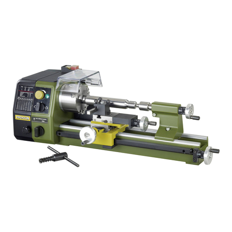
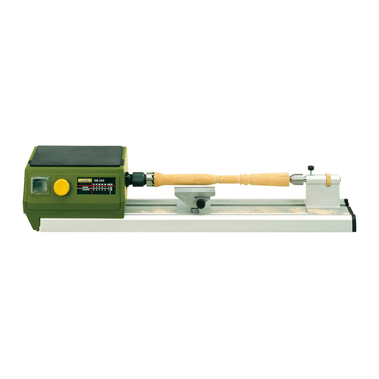
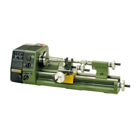
Proxxon PD 250/E User manual

PD 250/E
Manual

1
1 2 35 4
2 31
1
2
Fig. 2
Fig. 3
Fig. 1
Fig. 5Fig. 4
Fig. 9
Fig. 7Fig. 8
23 22
20
19
18
44 6
102524 12 111314151617
87 9
2 21 26 31 1
12
1
1
I
0
b
a
cdef
14 3 2
Fig. 6
-2-

Fig. 12
Fig. 10 Fig. 11
Fig. 15
Fig. 13 Fig. 14
Fig. 18
Fig. 16 Fig. 17
Fig. 21
Fig. 19 Fig. 20
1
1
2
ØD
L=3xD
1
22
1
3
3
3
1
3
1 4 5
2
1 2
2
1
1 4 23
15 43 2
L
W
1 432 Z1/ Z2
123
1
1
2
3
-3-

3
1
4
2
A
A
A
B
112 2
1
Fig. 22 Fig. 23 Fig. 24
Fig. 25
Fig. 28
Fig. 26 Fig. 27
23 4
1
1 2
1 2 3 5 4
1
1
2
2
Fig. 29
1
2
-4-

-5-
Contents
Page
Foreword5
Safety regulations 5
Legend 7
Description of the machine 7
Technical data 7
Installation and setting up 8
Switching on the machine 8
Operating the handwheels 8
Switching on the automatic feed 8
Working with the tailstock 9
Selecting the turning tool 9
Inserting the turning tool in the tool holder 9
Setting the spindle speeds 9
Calculating the maximum spindle speed 9
Clamping the work piece in the lathe chuck 10
Turning the jaws of the lathe chuck 10
Longitudinal turning 10
Face turning 10
Taper turning 10
Cutting offawork piece 10
Machining longer work pieces with tailstock and centre11
Fitting change gears for thread cutting 11
Thread cutting with the turning tool 11
Thread cutting using the top slide 12
Cutting left threads 12
Accessories for Lathe PD 250/E 12
Installing the centrelathe (No.24014) 12
Four-jaw chuck (No. 24036) 12
Fastening the drill chuck (No. 24020) 13
Fixed steady (No. 24010) 13
Careand Maintenance 13
General 13
Setting the guide play 13
Spareparts list 14
Foreword
Dear Customer,
By purchasing your PROXXON Lathe PD 250/E, you have chosen
agood-quality,high-grade machine. The latest production and
testing methods guarantee ahigh level of reliability for this
machine.
This instruction manual covers:
•safety regulations
•operation and maintenance
•spareparts list
Please read carefully!
Using this instruction manual will
•make it easier for you to get used to the machine,
•help prevent faults occurring due to improper use and
•increase the service life of your machine.
Keep this instruction manual in an easily accessible place.
Only operate this machine if you arequalified to do so and follow
the guidelines in this instruction manual.
PROXXON does not accept responsibility for the safe functioning
of the machine
•i
fitishandled in amanner which constitutes improper use,
•ifitisused for other purposes which arenot specified in the
instruction manual,
•ifthe safety regulations arenot observed.
Warranty claims areinvalid if
•the machine is incorrectly operated,
•the machine has not been sufficiently maintained.
In the interests of your safety,please always observe the safety
regulations.
Only use genuine PROXXON spareparts.
We reserve the right to make further alterations for the purpose of
technical progress.
We wish you every success with your machine.
Safety regulations
IMPORTANT
•Ensurethe workplace is tidy.
•Check the unit for damage beforeuse.
•(connection cable, protective devices, etc.), have defective
parts replaced by qualified personnel.
•This unit corresponds to the pertinent safety regulations.
Repairs (e.g., replacement of the power supply lead) may only
be performed by aqualified electrician.
•Never work without the safety equipment fitted.
•Donot use electrical power tools in the rain, in damp surroun-
dings or in the vicinity of flammable liquids or gases.
•Only use the tool when the handle is dry and free from grease.
•Avoid contact with earthed components, e.g., pipes, radiators,
ovens and refrigerators.
•Protect the connection lead from heat and sharp edges and
route it so it cannot be damaged.
•Donot remove the plug from the socket by pulling on the cable.
•Donot pick up the unit by the cable.
•Keep children and thirdparties away from the workplace.
•Keep tools in childsafe locations when not in use.
•Donot overload the tool.
•
Do not use the tool to perform operations for which it is not suitable.
•Replace blunt tools in good time.
•
Visually inspect application tools to ensurethey areingood
working order and suitable for the task prior to setting up the job.
•Fasten tools securely.
•Clean the unit thoroughly following all work.
•Disconnect the plug from the power supply when the unit is not
in use, beforeperforming maintenance, tool replacement or
repair work.
•Only plug the unit in when the unit is switched off.
•Always wear protective goggles (danger of tool breakage).
•Ifnecessary,wear aprotective dust mask.
•Only use appropriate working clothes (no loose sleeves, ties,
jewellery).
•Wear ahair net if you have long hair.
•Only use accessories and spareparts recommended by
PROXXON.
•Observe the max. permitted rotational speed.
•Ifnecessary,use dust extract equipment.
•Donot use the tool when you aretired or under the influence of
alcohol.
•Keep fingers away from rotating or fast moving tools
(saws, etc.).
•Keep the operation instructions in asafe place.

-6-
General safety instructions
Read and become familiar with this entireinstructions manual.
Learnthe tool`s applications, limitations and possible hazards.
1. KEEP GUARDS IN PLACE and in working order.
2. REMOVE ADJUSTING KEYS AND WRENCHES. Form habit of
checking to see that keys and adjusting wrenches areremoved
from tool beforeturning it on.
3. KEEP WORK AREA CLEAN. Cluttered areas and benches invite
accidents.
4. DON'T USE IN DANGEROUS ENVIRONMENT.Don't use power
tools in damp or wet locations, or expose them to rain. Keep
work area well lighted.
5. KEEP CHILDREN AWAY. All visitors should be kept safe
distance from work area.
6. MAKE WORKSHOP KID PROOF with padlocks, master swit-
ches, or by removing starter keys.
7. DON'T FORCE TOOL. It will do the job better and safer at the
rate for which it was designed.
8. USE RIGHT TOOL. Don't force tool or attachment to do ajob
for which it was not designed.
9. USE PROPER EXTENSION CORD. Make sureyour extension
cordisingood condition. When using an extension cord, be
suretouse one heavy enough to carry the current your product
will draw.Anundersized cordwill cause adropinline voltage
resulting in loss of power and overheating. Ta ble 1shows the
correct size to use depending on cordlength and nameplate
ampererating. If in doubt, use the next heavier gage. The
smaller the gage number,the heavier the cord.
Exception No. 1: The reference to the table and the table itself
may be omitted if astatement indicating the appropriate gage
and length is incorporated into the instruction.
Exception No. 2: The information regarding extension cords
need not be provided for apermanently connected tool.
10. WEAR PROPER APPAREL. Do not wear loose clothing, gloves,
neckties, rings, bracelets, or other jewelry which may get
caught in moving parts. Non-slip footwear is recommended.
Wear protective hair covering to contain long hair.
Exception: The reference to gloves may be omitted from the
instructions for agrinder.
11. ALWAYS USE SAFETY GLASSES. Also use face or dust mask
if cutting operation is dusty.Everyday eyeglasses only have
impact resistant lenses, they areNOT safety glasses.
12. SECURE WORK. Use clamps or avise to hold work when
practical. It's safer than using your hand and it frees both
hands to operate tool.
13. DON'T OVERREACH. Keep proper footing and balance at all
times.
14. MAINTAIN TOOLS WITH CARE. Keep tools sharp and clean for
best and safest performance. Follow instructions for lubricating
and changing accessories.
15. DISCONNECT TOOLS beforeservicing; when changing acces-
sories, such as blades, bits, cutters, and the like.
16. REDUCE THE RISK OF UNINTENTIONAL STARTING. Make
sureswitch is in offposition beforeplugging in.
17. USE RECOMMENDED ACCESSORIES. Consult the owner's
manual for recommended accessories. The use of improper
accessories may cause risk of injury to persons.
18. NEVER STAND ON TOOL. Serious injury could occur if the tool
is tipped or if the cutting tool is unintentionally contacted.
19. CHECK DAMAGED PARTS. Beforefurther use of the tool,
aguardorother part that is damaged should be carefully
checked to determine that it will operate properly and perform
its intended function check for alignment of moving parts, bin-
ding of moving parts, breakage of parts, mounting, and any
other conditions that may affect its operation. Aguardorother
part that is damaged should be properly repaired or replaced.
20. DIRECTION OF FEED. Feed work into ablade or cutter against
the direction of rotation of the blade or cutter only.
21. NEVER LEAVE TOOL RUNNING UNATTENDED. TURN POWER
OFF.Don't leave tool until it comes to acomplete stop.
Warning
Additional safety instructions for lathes:
For Your Own Safety Read Instruction Manual BeforeOperating Lathe
a) Wear eye protection.
b) Do not wear gloves, necktie, or loose clothing.
c) Tighten all locks beforeoperating.
d) Rotate workpiece by hand beforeapplying power.
e) Rough out workpiece beforeinstalling on faceplate.
f) Do not mount split workpiece or one containing knot.
g) Use lowest speed when starting new.
GROUNDING INSTRUCTIONS:
1. All grounded, cord-connected tools:
In the event of amalfunction or breakdown, grounding provides a
path of least resistance for electric current to reduce the risk of
electric shock. This tool is equipped with an electric cordhaving
an equipment-grounding conductor and agrounding plug.
The plug must be plugged into amatching outlet that is properly
installed and grounded in accordance with all local codes and
ordinances. Do not modify the plug provided -- if it will not fit the
outlet, have the proper outlet installed by aqualified electrician.
Improper connection of the equipment-grounding conductor can
result in arisk of electric shock. The conductor with insulation
having an outer surface that is green with or without yellow stripes
is the equipment-grounding conductor.Ifrepair or replacement of
the electric cordorplug is necessary,donot connect the equip-
ment-grounding conductor to alive terminal. Check with aquali-
fied electrician or service personnel if the grounding instructions
arenot completely understood, or if in doubt as to whether the
tool is properly grounded.
Use only 3-wireextension cords that have 3prong grounding plugs
and 3pole receptacles that accept the tool's plug.
Repair or replace damaged or worncordimmediately.
2. Grounded, cord-connected tools intended for use on asupply
circuit having anominal rating less than 150 volts:
This tool is intended for use on acircuit that has an outlet that
looks like the one illustrated in Sketch AinFigure30. The tool has
agrounding plug that looks like the plug illustrated in Sketch Ain
Figure30. Atemporary adapter,which looks like the adapter illust-
rated in Sketches Band C, may be used to connect this plug to a
2-pole receptacle as shown in Sketch Bifaproperly grounded
outlet is not available. The temporary adapter should be used only
until aproperly grounded outlet can be installed by aqualified
electrician. The green-colored rigid ear,lug, and the like, extending
from the adapter must be connected to apermanent ground such
as aproperly grounded outlet box.
Grounding methods
GROUNDING
ADAPTER
GROUNDING GROUNDING
MEANS
METAL SCREW
COVER OF GROUNDED
OUTLET BOX
<A> <B>
<C>
<D>
PIN
PIN
Fig. 30
-7-
Table 1
Minimum gage for cord
Effective date for Table 1changed from November 1, 1995 to
November 11, 1996
AmpereRating Volts Total length of cordinfeet
120 V25ft. 50 ft. 100 ft. 150 ft.
240 V50ft. 100 ft. 200 ft. 300 ft.
MoreNot MoreAWG
Than Than
06 18 16 16 14
61018161412
10 12 16 16 14 12
12 16 14 12 Not Recommended
Legend (Fig. 1)
1. Main spindle
2. Lathe chuck
3. Turning tool holder
4. Rotating centre
5. Flange surface for milling unit
6. Sleeve
7. Clamp screw for sleeve
8. Tailstock
9. Sleeve adjusting handwheel
10. Handwheel for leadscrew
11. Clamp screw for tailstock
12. Leadscrew
13. Adjusting handwheel for top slide
14. Topslide
15. Support
16. Cross-slide
17. Adjusting handwheel for cross-slide
18. Clutch switch for automatic feed
19. Drive gearbox cover with speed table
20. Switch for anticlockwise rotation stop clockwise rotation
21. Main switch
22. Function display
23. Control
24. Hollow hexagon wrench
25. Lathe chuck wrench
Description of the machine
The PROXXON lathe PD 250/E is an extensible system which
consists of
•
solid shaft electronics for high torques over the entirespeed range
•automatic feed
•lathe chuck and
•rotating centre
for machining steel, brass, aluminium and plastics.
It can also be used for face turning, longitudinal turning and
thread cutting.
The machine is also suitable for boring, milling work and grooving
by using the appropriate accessories.
The ribbed, grey cast iron machine bed with ground prismatic
guideways ensures vibration-free work.
Warning
This Lathe is for indoor use only.Donot expose to rain or use in
damp locations.
Do not attempt to modify this tool or create accessories not
recommended for use with this tool. Any such alternation or modi-
fication is misuse and could result in hazardous condition leading
to possible serious injury.
Technical data:
Centredistance 9.8” (250 mm)
Centreheight 2.76" (70 mm)
Height above support 1.7" (43 mm)
Holding capacity
–Inner jaws 0.1" to 1.1" (2 -27mm)
–Outer jaws 1" to 2.8" (25 -75mm)
Cross-slide travel 2.4" (60 mm)
Topslide adjustment 1.8" (45 mm)
Spindle bore0.4" (10.5 mm)
Nose support on chuck side MK1/short
Tool holder 0.3" x0.3" (8x8 mm)
Machine dimensions approx. 22" x10,63" x6,7"
(560 x270 x170 mm)
Weight approx. 26,5 lb
Possible thread leads 0.5, 0.625, 0.7, 0.75, 0.8, 1.0, 1.25, 1.5 mm
Spindle speeds
–byshifting the V-belt 300/900/ and 3000 rpm
–bycontrol 25% to 100%
Feed 0.05 and 0.1 mm/revolution
Sleeve motion 1.2”
Sleeve for morse taper MK 1/short
Motor
Voltage: 115 Volt, 60 Hz,~
Power consumption 140 Watt
Noise emission 70 dB (A)
Only to be operated in closed rooms!
Do not dispose of the electrical device
in the household waste!
Always work with hearing protection!
Wear safety glasses!
Installation and setting up
Warning
To avoid injury from unexpected starting or electrical shock, do not
plug the power cordinto apower source receptacle during
unpacking and assembly.This cordmust remain unplugged
whenever you areworking on the lathe.
If any part is missing or damaged, do not plug the lathe in until the
missing or damaged part is replaced, and assembly is complete.
To avoid electrical shock, use only identical replacement parts
when servicing grounded tools.

-8-
The standardequipment of the PROXXON Lathe PD 250/E
consists of the following parts:
•l
athe complete with motor,automatic feed and three jaw chuck
with chuck wrench
•rotating centre
•tool kit
•c
hange gear kit for thread turning
•t
ool holder.
The floor space must be even, vibration-free and stable. The
machine must be fastened to astable work bench using the bores
provided.
Important
When lifting the machine, ensurethat the plastic cover of the
drive gearbox is closed. If it is not, the cap may break.
All naked metal parts aresupplied in acorrosion protection preser-
vative.
This preservative must be washed offwith paraffin oil beforeusing
for the first time.
All naked guides and spindles must then be thoroughly oiled.
Warning
For your safety,never connect the plug to the power source recept-
acle until the assembly and adjustment steps arecompleted, and you
have read and understood the safety and operating instructions.
To avoid injury from accidental start, make surethe switch is in the
OFF position and the plug is not connected to the power source
receptacle beforechanging any parts or tools (i. e. cutter)
Switching on the machine
Warning
To avoid injury from accidental start, make surethe switch is in the
OFF position and the plug is not connected to the power source
receptacle beforemaking any adjustments.
Caution!
Please comply with the following when commissioning and wor-
king with the PD 250/E: Your machine is equipped with an auto-
matic safety shutdown and can only be operated when the chuck
guardisfolded down! As soon as the chuck guardisfolded up
during operation, the motor will shut offautomatically! Only work
with afolded down chuck guard! If the guardisdefective, the
machine may no longer be operated!
Caution:
Beforeinserting the mains plug, please check if the information
on the rating plate matches the local conditions of your mains
supply.Ifthey do not match, then damage or hazards during work
could be result!
Always work within the intended performance range! Avoid spind-
le blockages caused by overloading. In the event of the spindle
blocking during operation, please switch offthe machine imme-
diately and configurethe feed and infeed for further machining to
avoid overloading of the machine.
Caution!
Beforeinserting the mains plug, please check if the information
on the rating plate matches the local conditions of your mains
supply.Ifthey do not match, then damage or hazards during work
could be result!
Avoid unnatural body positions. Ensurethat you arestanding in a
safe position and keep your balance.
1. Set selection switch 2(Fig. 2) to "0" position.
2.
Switch on main switch (1). The function display should now illuminate.
3. Turn the selection switch (2) to the right for normal turning.
4. Turn the selection switch to the left for anticlockwise rotation.
5. When you have finished working, switch offthe machine again
using the main switch. Only then is the machine completely dis-
connected from the mains.
Operating the handwheels
Important
If the support will not move easily,release screw 1(Fig. 3) slightly.
Note:
The handwheels for the leadscrew,crossslide, top slide and tail-
stock sleeve produce a1mmfeed when turned once.
Important
If the automatic feed is switched on, manual adjustment of the
support is not possible.
1. Turn the handwheel 2(Fig. 3) for the crossslide, the slide and
the tool holder move at right angles to the bed.
Example: One turnofthe handwheel
=1mmadvance
=2m
mchange in diameter
2. Turn the handwheel (3) for the top slide, the top slide moves
parallel to the bed.
3. Turn the handwheel 1(Fig. 4) for the support adjustment,
the support (2) moves lengthwise.
4. Turn the handwheel 1(Fig. 5) for the sleeve, the sleeve moves
lengthwise.
Switching on the automatic feed
Important
Only switch on the feed when the machine is stationary.
When the automatic feed is switched on, always ensurethat the
support or turning tool do not collide with the lathe chuck or
tailstock.
1. Turn the switch 1(Fig. 6) to the right.
2. Turn the switch to the left to switch offthe feed.
If stiff, slightly move the handwheel of the leadscrew.
Note:
Please note the sticker on the inside of the drive gearbox when
adjusting the feed.
The support always moves from right to left when the spindle is
turning normally (clockwise rotation) and the automatic feed is
switched on. This is also the normal feed when turning.
Of course, the support can also be moved back to the output
position automatically.
To do so, switch offthe machine, slightly draw back the turning
tool and then set the switch 2(Fig. 2) to anticlockwise rotation.
Working with the tailstock
Note:
Amount is located on the sleeve for the drill chuck or rotating cen-
trewith morse taper,size MK 1/short.
Important
Receiving tapers must always be perfectly clean.
Dirt, especially metal chips, affect the precision and can render
the sleeve and shank taper unusable

-9-
1. Release the clamp screw 4(Fig. 7), push the tailstock (2) on the
guide into the required position and retighten the clamp screw.
2. To insert atool, e.g. the centre1(Fig. 7), extend the sleeve
approx. 10 mm by turning the handwheel 3.
3. Insert the centre1(Fig. 7) and shank taper firmly into the sleeve
by hand. The shank taper is secureand cannot be removed
from the front.
4. To release an inserted tool, turnhandwheel (3) to the left to
stop.
5. Then turnapprox. one further turnagainst the resistance. The
taper is released and can be removed.
6. The sleeve can be clamped in any position by tightening the
screw 5(Fig. 7).
Selecting the turning tool
Warning
Use only accessories recommended for this lathe. Follow the
instructions that accompany accessories. Use of improper acces-
sories may cause hazards.
For your own safety,use only lathe cutters sized and recommended
for this lathe. Follow the instructions that accompany the cutters.
Important
For proper turning, it is essential that:
•the correct turning tool has been selected for the appropriate
purpose
•the blade of the turning tool is sharp
•the blade of the turning tool sits exactly in the "centre" position
•and is operated at the correct speed.
Inside turning tools (a) (Fig. 8)
•are used for interior diameter turning.
Cutofftools (b)
•for plungecutting grooves and cutting offwork pieces.
Thread tools (c)
•are used for cutting outer threads. Finishing or tapering tools (d)
•are used to achieve aclean surface when removing small chips.
Right side tools (e)
•are used to remove as many chips as possible in ashort time
when machining towards the right, regardless of the surface
quality of the work piece.
Left side tools (f)
•are used to remove as many chips as possible in ashort time
when machining towards the left, regardless of the surface qua-
lity of the work piece.
Inserting the turning tool in the tool holder
Important
Give the turning tool as short an overhang as possible. Allowing
the tool to project too far leads to vibrations, imprecision and an
unclean surface.
1. Unscrew both fastening screws 1(Fig. 9) until the selected tur-
ning tool (3) fits into the mount.
2. Give the turning tool as short an overhang as possible. Allowing
the tool to project too far leads to vibrations, imprecision and
an unclean surface.
3. Insert the turning tool (3) and tighten the fastening screws (1).
4. Move the turning tool to the centre(4) and check whether the
height has been correctly adjusted.
Note:
For height deviations, small metal sheets (2) (e.g. valve sensor
gauges) must be placed beneath the complete surface.
Setting the spindle speeds
Important
Always disconnect the mains plug beforeworking on the drive
gearbox. Risk of injury.
The spindle speed must be adjusted to suit the work piece
material and diameter.
Calculating the maximum spindle speed
The required spindle speed can be calculated when the specified
maximum cutting speed for acertain material is known.
Maximum permissible spindle speed
Cutting speed x1000
=
Working piece diameter x3.14
Example:
Awork piece with adiameter of 20 mm is to be turned at acutting
speed of 50 rpm.
50 x1000 =796/min
20 x3.14
By shifting the V-belt (Fig. 10), set to the next highest speed. In
this case, the speed is 1600 rpm. The correct speed is now set via
the controls, and hereisimportant to note that the controls cover
aspeed range of 25% to 100%, i.e. in our example, 400 rpm to
1600 rpm.
1. Release the clamp screw from the drive gearbox and open the
flap.
2. Release Vbelt tensioner 1(Fig. 10).
3.
Adjust the relevant speed by shifting the Vbelt according to Fig. 11
4. Retighten Vbelt tensioner.Note the appropriate tension of the
Vbelt. Overtensioning increases the wear of the belt and
bearing and reduces the motor power.
5. Close the drive gearbox beforecommencing turning work.
Clamping the work piece in the lathe chuck
Warning
To avoid injury from accidental start, make surethe switch is in the
OFF position and the plug is not connected to the power source
receptacle beforechanging any parts or tools (i. e. cutter).
Important
If work pieces areclamped in the lathe chuck using the tail stock
without asteady,the projection (Fig. 12) must not be greater than
three times the diameter of the material (L =3xD).

-10-
Note:
The normal lathe chuck has three steel jaws, which areuniformly
adjusted and centreround work pieces automatically.
In the normal position, work pieces can be clamped up to adia-
meter of 27 mm. After turning the jaws, it is possible to clamp up
to adiameter of 75 mm.
Do not leave the wrench in the lathe chuck. Risk of injury.
Clamping alonger work piece which has been guided through the
spindle and is projecting to the left increases the risk of injury.In
this case, be particularly careful to ensurethat no objects are
caught in the rotating shaft. Protect this zone separately by fuse.
1. Turn the lathe chuck 2(Fig. 12) using the wrench (1) until the
work piece fits in the mount.
2. Clamp the work piece tightly and remove the wrench from the
chuck.
3. Check the running of the work piece and correct if necessary.
Turning the jaws of the lathe chuck
Remove mains plug.
Do not clamp work pieces with adiameter greater than 71 mm.
The clamping force of the jaws is then too small and the work
piece may become loose. Danger of accident.
Note:
1.
Open the lathe chuck until the jaws arereleased from the chuck.
The jaws arenumbered.This occurs in the sequence 3, 2and 1.
2. Turn the jaws and first insert no. 3inone of the three guides
(Fig. 13).
3. Press jaw no. 3inthe direction of the lathe chuck centreand
simultaneously turnthe chuck wrench in the "clamp" direction.
4. When the thread worm (4) has gripped jaw no. 3, insert jaw
no. 2into the next guide (clockwise).
5. Repeat proceduredescribed above with nos. 2and 1.
6. Then check that all jaws areinthe central position.
7. If you want to work with the inside jaw chuck again, repeat the
steps described above in the reverse order,i.e. first insert jaw
nos. 1and 2, and then 3.
Longitudinal turning
Do not allow the support or turning tool to collide with the
lathe chuck.
Note:
1. Select the spindle speed according to the table on your lathe.
2. Adjust the required speed by shifting the belt in the drive gear-
box (see previous section).
3. Clamp aright side tool 2(Fig. 14) in the tool holder (see pre-
vious section).
4. Switch offthe automatic feed (3).
5. Move the support from the right to the left of the work piece.
6. Adjust the cutting depth using the crossslide (1).
7. Switch on the machine (clockwise rotation).
8. Manually feed or switch on the automatic feed (3), do not
overload the machine.
9. Beforeswitching on the machine, manually check whether the
spindle, chuck and work piece arerunning free.
Note:
If the top slide is not necessary,itisadvisable to clamp it with the
screw 4(Fig. 14). The turning performance is improved by elimina-
ting play.
Face turning
Important
The cutting speed from outside inwards differs considerably for
work pieces with larger diameters. Therefore, push the cross-
slide slowly and sensitively.
Note:
This method of working is used to turnoff the face of awork piece.
1. Adjust the right side tool by approx. 2° to 3° (Fig. 15).
2. Move the cross-slide from outside inwards (to the centre) with
the turning tool.
Taper turning
The top slide (Fig. 16) is equipped with ascale and can be swivel-
led by 45° on either side of zerofor taper turning. To do so, release
fastening screw (1), adjust top slide and then re tighten.
Cutting offawork piece
Important
Give the cutofftool as short an overhang as possible (half of the
diameter of the work piece +1mm). Similarly,give the work piece
as short an overhang as possible.
Note the exact centreheight of the cutofftool. Work at low
speeds and cool blade as often as possible.
1. Clamp the cutofftool at right angles in the tool holder.
2. Sensitively move the crossslide from outside inwards (to the
centre) with the turning tool. Machining longer work pieces with
tail stock and centre
Machining longer work pieces with
tailstock and centre
If the chuck projection is greater than three times the diameter of
the work piece, the work piece must be held at the right end by
the tailstock and centre.
For this purpose, acentreboremust be drilled on the right side of
the work piece.
1. Face turnthe right face.
2. Insert the drill chuck (accessories) in the tailstock and clamp
the centring drill.
3. Move the tailstock with drill chuck and centring drill up to the
face of the work piece.
4. Switch on the machine and drill centreboreusing the sleeve
feed.
5. Replace the drill chuck with the rotating centre1(Fig. 17).
6. Insert the centreinthe centreboreand clamp the tailstock (3)
securely.
7. Advance the sleeve (2) until all play is eliminated.
8. Securethe sleeve using aset screw (4).

-11-
Fitting change gears for thread cutting
Note:
The PROXXON Lathe PD 250/E offers Youthe possibillity to cut
metric threads. Youfind alabel on the inside of the cover of the
gearbox of the machine to get the desired gear combination. The
number of teeth is imprinted on all change gears. All required
change gears areincluded in delivery.
The PD 250/E is supplied with installed gear arm and the change
gear combination for the automatic feed of 0.05 mm/revolution. It
is only necessary to replace the change gears installed on the gear
arm for thread cutting.
For example, if cutting athread with apitch of 1.0 mm, the table
on the drive gearbox will show the following data:
W15-gear on the main spindle with 15 teeth. This gear is already
installed on the shaft and must not be replaced.
Z115-Z220-Intermediate gear for the toothed belt of the main
spindle with15 teeth and permanently linked gear for the leadscr-
ew with 20 teeth.
L20 -leadscrew gear with 20 teeth. Of course all operations to cut
ainch system based thread areanalogous to the described exam-
ple with the metric thread! Note the different units for the thread
pitch on the labels inside the gear box cover!
1. Release the clamp screw 1(Fig. 18) and tilt the gear arm (2)
slightly upwards to remove the toothed belt (4).
2. Remove the fastening screws (3 and 5) from the normal gears
for the automatic feed.
3. Fasten the change gear "Z1-Z2" with 15/20 teeth (Fig. 19) to
the gear arm (3) using the screw (2), pulley,reduction sleeve
and nut. Please observe: The change gear "Z1-Z2" runs freely
between pulley and sleeve.The washer prevents the toothed
belt from becoming detached from the gear"Z1".
4. Do not yet tighten the fastening screw nut (2) (off-centre
adjustment must still be possible).
5. Release the set screw (1), remove the change gear "L40" and
replace with the change gear "L20".
6. Please observe: The grain of the leadscrew change "L" must
always point to the lathe chuck. The set screw (1) must be
clamped onto the flattened part of the shaft.
7. To ensurethat thereissufficient play between the change
gears, always insert astrip of newspaper between the teeth
when pushing the change gears together.The thickness of the
newspaper should correspond to the required tooth play.
8. Push the axle of the change gear "Z1-Z2" onto the arm so that
it contacts the leadscrew gear "L" and then tighten the
fastening screw nut (2).
9. Position the short toothed belt for the connection between the
gears "W" and "Z1" on the main spindles.
10.
Push the gear arm (3) downwards and tighten the clamp screw (4).
Auseful hint:
Ap
erfect, good-quality thread can only be cut by using the top
slide. Advancing the thread tool is performed using the cross-slide
as described above.
However,this causes the top slide to shift by 0.025 mm to the left
and the same distance to the right.
The chip in the thread is thereforealways only removed from one side.
Once the full thread depth has been reached, afinal full cut is
made by advancing slightly.
Thread cutting with the turning tool
Important
Use the lowest speed when cutting threads and proceed with
utmost caution.
The automatic feed must remain switched on until completion of
the thread. Disengaging between individual steps renders further
work impossible.
Only switch over the motor switch once the lathe chuck has come
to acomplete standstill. Switching over immediately increases
wear and reduces the service life of the motor.
Note:
For the following operations, the work piece must be machined
completely and have the correct thread outer diameter.
It is advisable to work out achamfer at the beginning of the
thread. The thread turning tool must be clamped at an angle of 90°
exactly.
1. Clamp the work piece.
2. Switch offthe automatic feed and set the turning tool to the
starting position.
3. Switch on the machine 2(Fig. 20) (clockwise rotation).
4. Advance the turning tool on the cross-slide (1) and engage
feed (3).
5. Switch offthe machine when the required thread length has
been reached (2).
6. Move back the turning tool slightly with the cross-slide.
7. Move the support back to the output position. To do so, switch
over the turning direction of the main spindle.
8. Advance the turning tool and repeat the steps described above
until the required thread depth is reached.
Thread cutting using the top slide
Aperfect, good-quality thread can only be cut by using the top
slide (accessories).
Advancing the thread tool is performed using the cross-slide as
described above.

-12-
However,this causes the top slide to shift by 0.025 mm to the left
and the same distance to the right.
The chip in the thread is thereforealways only removed from one side.
Once the full thread depth has been reached, afinal full cut is
made by advancing slightly.
Cutting left threads
To cut left threads, the intermediate gear 1(Fig. 21) must be instal-
led between "Z1-Z2"and the leadscrew gear "L1".
In doing so, the turning direction of the leadscrew is reversed. The
support runs from right to left when the chuck is turning clockwise.
Installation and operation areasdescribed above.
Accessories for Lathe PD 250/E
Note:
The described accessories arenot included in the standardequipment.
Installing the centrelathe (No. 24014)
When using acentrefixed to the tailstock, regular lubrication of
the centreand centreboreisnecessary to prevent the temper
from loosening.
Note:
Longer work pieces areclamped between the brad points of the
main spindle and tailstock.
The work piece must have acentreboreonboth faces.
An exact cylindrical work piece is only achieved if the points align
in the horizontal position.
1. Remove three fastening screws from the three-jaw chuck and
remove chuck.
2. Thoroughly clean the fit for the driving disc and centreand its fit
in the main spindle.
3. Insert the centre 4(Fig. 22) in the fit (1) of the main spindle.
4. Fit the driving disc (2) and fasten with three screws (3).
5. Push the lathe carrier 1(Fig. 23) onto the work piece (driving
pin outwards) and tighten the fastening screw (2).
6. On the left side, insert driving pin in one of the three long holes
on the driving disc and the centreinthe centrebore.
7. On the right side, attach the work piece using the tailstock and
fixed or rotating centre.
8. To remove the centre, guide asuitable aluminium or brass rod
through the main spindle from left to right.
9. Hold the centreand release by lightly tapping the rod.
Four-jaw chuck (No. 24036)
In the normal clamping jaw position, only work pieces with an
edge of up to max. 30 mm long can be clamped. The maximum
length is 80 mm in the reverse position.
Larger work pieces arenot securely held. Danger of accident.
Collet chuck unit and collet chucks
Remove mains plug.
Note:
Round, oval, squareand irregularly shaped work pieces can be
clamped as it is possible to adjust the jaws individually.
Centric or eccentric clamping is possible.
Unlike the threejaw chuck, centring of the work piece must be per-
formed manually.
1. Detach the three-jaw chuck and attach the four-jaw chuck.
2. Open the four jaws, clean the contact faces and clamp the
work piece lightly according to visual estimation.
3. Move the support and turning tool onto the plane surface of the
work piece.
4. Turn the chuck by hand to establish symmetrical deviations.
6. Adjust by opening one of the jaws and reset the opposite jaw
accordingly.
7. Tighten all four jaws evenly,alternating crosswise.
Collet set with ER 20 collets (No. 24038)
Important
Always use the correct collet chuck to suit the work piece.
Chucks with an oversized diameter aredestroyed.
Important
Never tighten the union nut when thereisnowork piece inserted.
The collet chuck unit is especially suitable for processing round
parts with great precision. The truth of running is considerably
greater than when working with ajaw chuck.
1. Remove three fastening screws from the threejaw chuck and
remove chuck.
2. Thoroughly clean the fit for the collet chuck mount 2(Fig. 24)
and the fit in the main spindle (1).
3. Attach the collet chuck mount (2) using four fastening screws (3).
4. Insert the collet chuck (6) and loosely screw in the union nut (5).
5. Insert the appropriate work piece in the collet chuck and tighten
the union nut (5) using the tool pins (4).
6. Remove the pins 4(Fig. 24) for tightening the union nut (5)
immediately after tightening.
Fastening the drill chuck (No. 24020)
The jaws (2) must only touch the work piece and must not jam.
Otherwise thereisarisk of the work piece surface becoming
scratched and the motor becoming overloaded.
1. Remove the rotating centrefromthe sleeve. Thoroughly clean
the grease and dirt from the shank taper and chuck bore.
2. Insert the journal in the sleeve and firmly push onto the drill
chuck.
Note:
Releasing the drill chuck is performed in the same way as the
rotating centre.
Fixed steady (No. 24010)
The steady is particularly suitable for hollowing out long work
pieces with diameters up to 40 mm.
1. Release the fastening screw 4(Fig. 25) and position retaining
plate (3) crosswise.
2. Place the steady on the bed guide and set to the required
position.
3. Swivel the retaining plate (3) parallel to the steady base and
tighten fastening screw (4).

-13-
4. Release all clamp screws (1) and drive the individual retaining
jaws (2) onto the work piece
If the work piece is not round and smooth at the support point, it
must first be turned round.
Lubricate the jaws and work piece regularly when turning.
5. Check that the work piece is positioned in the steady free of
play and retighten clamp screws (1).
Careand Maintenance
Cleaning
Caution!
Always disconnect the mains plug for all adjustment and mainten-
ance work! Risk of serious injuries or damage due to inadvertent
starting up of the device, or hazarddue to electric shock!
1. After use, thoroughly clean all chips from the machine using a
brush or handbrush. Do not use compressed air for cleaning.
2. Regularly lubricate or oil all moving parts, spindles and guides!
The outside of the housing can be cleaned with asoft, dry or
damp cloth. Do not use compressed air when cleaning.
It is possible to use mild soap or other suitable cleaning agent
here. Solvents or cleaning agents containing alcohol (e.g. petrol,
cleaning alcohol etc.) should be avoided, since these can attack
the plastic housing casings as well as wash offthe lubricants. To
avoid fireortoxic reaction, never use gasoline, naphtha, acetone,
lacquer thinner,orsimilar highly volatile solvents to clean the lathe.
Do not allow brake fluids, gasoline, or penetrating oils to come in
contact with the plastic parts. They contain chemicals that can
damage or destroy plastics.
Please observe:
All electrical or mechanical repairs should be done only by quali-
fied service technicians. When servicing use only PROXXON repla-
cement parts. Use of any other parts may create ahazardorcause
product damage.
Any attempt to repair or replace electrical parts on this lathe may
create ahazardunless repair is done by aqualified service techni-
cian. Repair service is available at your PROXXON service center.
Lubricating:
Lubricate or oil all parts according to lubrication diagram (Fig. 26).
A=oil /lubricate beforeuse
B=oil /lubricate once amonth
Adjusting the play of the guides (Fig. 27)
Turn switch OFF and always remove plug from power source befo-
re making any adjustments or repairs.
Note:
Even if the guides areregularly lubricated or oiled, it is unavoidable
that the guides will exhibit play after some time due to wear.
The proceduredescribed hereusing the example of the upper car-
riage is the same for all guides, thereforeitapplies analogously to
the other guides on your lathe. For that reason they will not be
treated separately here. Adjust the guides according to the motto:
As "tightly" as necessary,aseasy running as possible!
Please consider: If guides areset too closely,this causes higher
operating forces as well as increased wear!
1. Release and slightly unscrew the counter nuts 1ofthe adju-
sting screws 2for the upper carriage 3using an open-end
spanner 5.
2. Evenly turninthe adjusting screws 2with an Allen key 4until
the play is eliminated.
3. Retighten the counter nuts 1. In the process, hold the adjusting
screws 2inposition with the fixed spanner 5sothat they do
not misadjust again.
4. Turn over the machine and slightly unscrew the set screw 2
(Fig. 28).
5. Then check if the support can still be moved easily and if it runs
completely without play.
Adjusting the play of the handwheels (Fig. 29):
Just as for the guides, handwheel wear during operation cannot be
avoided which ensures that the backlash increases slowly but con-
sistently.Tominimise this again, please proceed as follows:
1. Hold on to the handwheel 1and release the cap nut 2.
2. Turn the handwheel slightly to the right.
3. Retighten the cap nut while still holding the handwheel.
Please consider hereaswell:
The complete elimination of the backlash and atoo "tight" adjust-
ment for the handwheels is unreasonable: If the handwheels are
set too closely,this causes higher operating forces as well as
increased wear hereaswell!

-14-
29
6 7 8 9 10 11 12 13 14
22/23/24
25/26
4/5
321
28 27 20 18/19 1721 16 15
Spare parts list
Assembly 00: Change gears

-15-
Spare parts list
Please order spareparts in writing from PROXXON Central Service
(Address on back of instruction manual)
Assembly 00: Change gears
Part No.: Designation
24002-00-01 Fastening screw
24002-00-02 Washer
24002-00-03 Change gear 30/16
24002-00-04 Toothed belt T5-40
24002-00-05 Toothed belt T5-50
24002-00-06 Change gear 15 teeth
24002-00-07 Set screw
24002-00-08 Bushing
24002-00-09 Bushing
24002-00-10 Nut
24002-00-11 Nut
24002-00-12 Nut
24002-00-13 Clamp screw for gear arm
24002-00-14 Set screw for automatic feed
24002-00-15 Clutch
24002-00-16 Gear arm
24002-00-17 Set screw
24002-00-18 Leadscrew 20 teeth
24002-00-19 Leadscrew 40 teeth
24002-00-20 Intermediate gear 17 teeth
24002-00-21 Fastening screw
24002-00-22 Intermediate gear 15/30 teeth
24002-00-23 Intermediate gear 15/28 teeth
24002-00-24 Intermediate gear 15/25 teeth
24002-00-25 Intermediate gear 15/20 teeth
24002-00-26 Intermediate gear 15/32 teeth
24002-00-27 Change gear 64/16 teeth
24002-00-28 Washer
24002-00-29 Fastening screw

-16-
Spare parts list
Assembly 00: Change gears

-17-
Spare parts list
Please order spareparts in writing from PROXXON Central Service
(Address on back of instruction manual)
Assembly 00: Change gears
Part No.: Designation Part No.: Designation
24002-01-01 Brand-Logo
34002-01-02 Speed table
24002-01-03 Mat
24002-01-04 Gearbox
24002-01-05 Screw
24002-01-06 Pin
24002-01-07 Gearbox hinge
24002-01-08 Strain relief
24002-01-09 Screw
34002-01-10 Power supply cable
34002-01-11 Board(without LED)
34002-01-12 Switch
24002-01-13 Mat, short
24002-01-14 Chuck cover
24002-01-15 Sleeve
24002-01-16 Screw
24002-01-18 Screw
24002-01-19 Main spindle
24002-01-20 Motor Cover
24002-01-21 Main spindle bearing
24002-01-22 Label
24002-01-23 LED
24002-01-24 Rotary knob
24002-01-25 Rotary switch
24002-01-26 Guide-Screw-Label
24002-01-27 Screw
24002-01-28 Headstock
24002-01-29 Switch for direction
24002-01-30 Screw
24002-01-31 Spacer ring
24002-01-32 Motor
24002-01-33 Ring nut
24002-01-34 Bushing
24002-01-35 Knurled nut
24002-01-36 Screw
24002-01-37 Screw
24002-01-38 Ball bearing
24002-01-39 Shaft
24002-01-40 Tensioner poully
24002-01-41 Screw
24002-01-42 Screw
24002-01-43 Main spindle belt pulley
24002-01-44 Nut
24002-01-45 Set screw
24002-01-46 Motor belt pulley
24002-01-47 Retaining ring
24002-01-48 Washer
24002-01-49 Spacer sleeve
24002-01-50 Intermediatebelt pulley
24002-01-51 Drive-belt, main spindle
24002-01-52 Drive-belt, engine
24002-01-53 Screw
24002-01-54 Bearing
24002-01-55 Screw
24002-01-56 Plate
24002-01-57 Bushing
24002-01-58 Shaft
24002-01-59-1 Motor mounting plate, big
24002-01-59-2 Motor mounting plate, small
24002-01-60 Nut
24002-01-61 Nut
24002-01-62 Cam
24002-01-63 Screw
24002-01-64 Circlips
24002-01-65 Switch
24002-01-66 Lathe chuck (not shown)
24002-01-67 Lathe chuck spanner (not shown)
24002-01-68 Plate
24002-01-69 Bearing
34002-01-97 Article packaging (not shown)
34002-01-99 Operating instructions (not shown)

-18-

-19-
Spare parts list
Please order spareparts in writing from PROXXON Central Service
(Address on back of instruction manual)
Assembly 02: Bed with leadscrew
Part No.: Designation
24002-02 -01Lathe bed
24002-02 -02Cover
24002-02 -03Screw
24002-02 -04Scale ring
24002-02 -05Set screw
24002-02 -06Lead screw bearing
24002-02 -07Screw
24002-02 -08Screw
24002-02 -09Pin
24002-02 -10Cap nut
24002-02 -11Hand wheel
24002-02 -12Spring
24002-02 -13Guide screw
24002-02 -14Nut for guide screw
24002-02 -15Washer
24002-02 -16Screw
24002-02 -17Bush bearing
24002-02 -18Coupling shaft
24002-02 -19Coupling piece
24002-02 -20Knob for automatic feed
24002-02 -21Screw
24002-02 -22Set screw
24002-02 -23Housing
24002-02 -24Set screw
24002-02 -25Lead screw coupling peace
24002-02 -26Coupling shaft

-20-
Spare parts list
Assembly 03: Support
35
34
33
32
31
30
29
28
27
26
25
24
23
22
21
67
20 4985
16
15
14
13
18
17
19
54
321
6
78
9
12 11 10
Other manuals for PD 250/E
1
Table of contents
Other Proxxon Lathe manuals

Proxxon
Proxxon DB 250 User manual

Proxxon
Proxxon PD 250/E User manual

Proxxon
Proxxon PD 230E Assembly instructions

Proxxon
Proxxon FD 150/E User manual

Proxxon
Proxxon UT 400 CNC User manual

Proxxon
Proxxon 24062 User manual

Proxxon
Proxxon PD 230E User manual

Proxxon
Proxxon DB 250 User manual

Proxxon
Proxxon PD 400 Quick guide