Pyle PDWM3360 User manual

WirelessMicrophoneSystem
PDWM3360-PDWM3365
PDWM3360 PDWM3365

www.PyleUSA.com www.PyleUSA.com
CATALOG
1. FOREWORD --------------------------------------------------------------------------------------------- 2
3. SYSTEM FEATURES ----------------------------------------------------------------------------------- 2
4. SYSTEM TYPE ------------------------------------------------------------------------------------------- 2
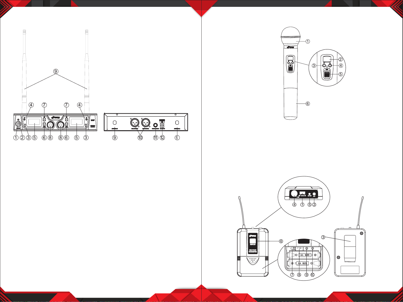
5. DUAL CHANNEL RECEIVER FEATURES ------------------------------------------------------- 3
6. TRANSMITTER FUNCTION & FEATURES --------------------------------------------------- 4-5
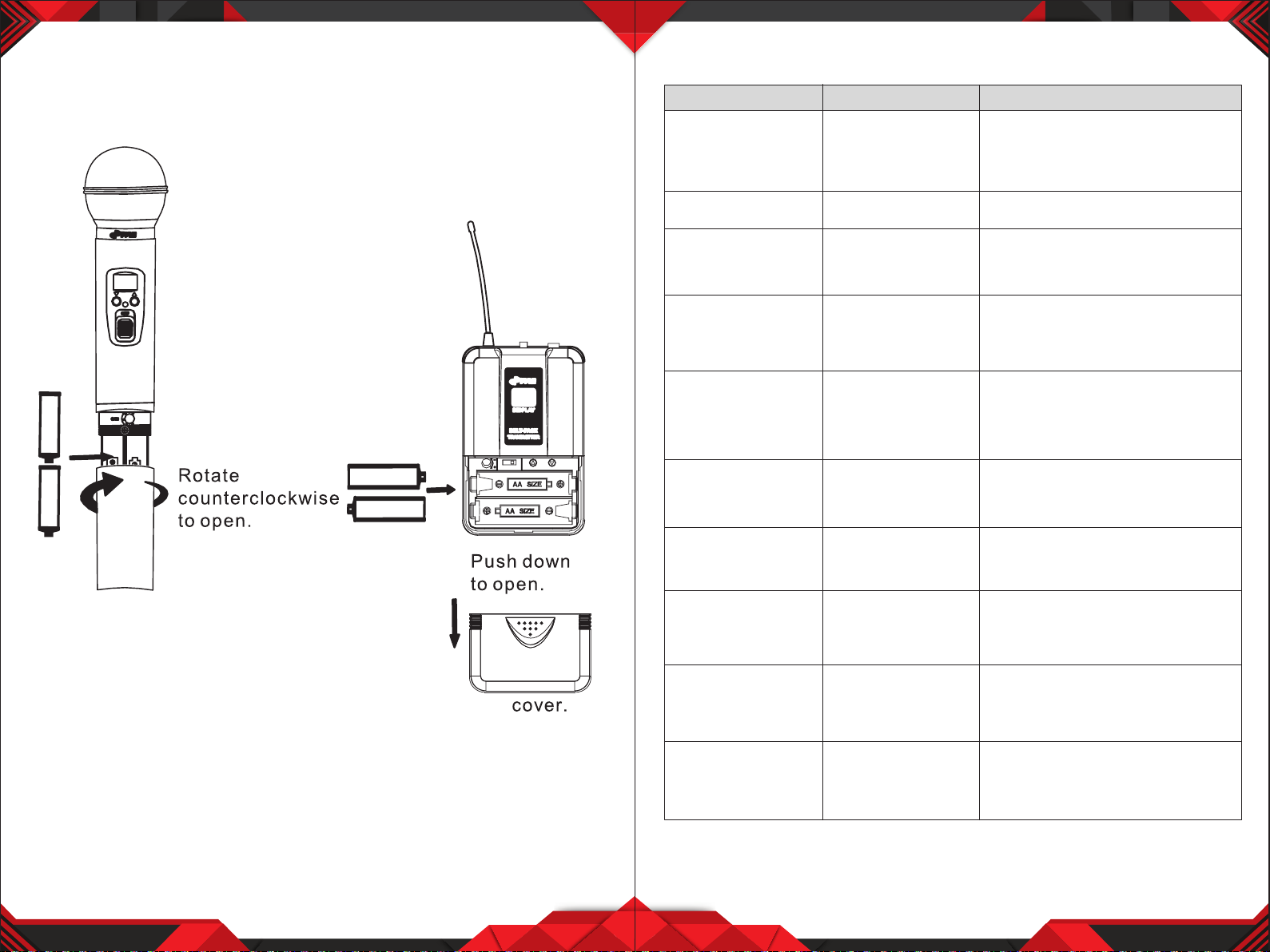
7. TRANSMITTER BATTERY INSTALLATION ----------------------------------------------------- 6
8. BODYPACK TRANSMITTER CONNECTION --------------------------------------------------- 7
9. SYSTEM CONNECTIONS --------------------------------------------------------------------------- 8
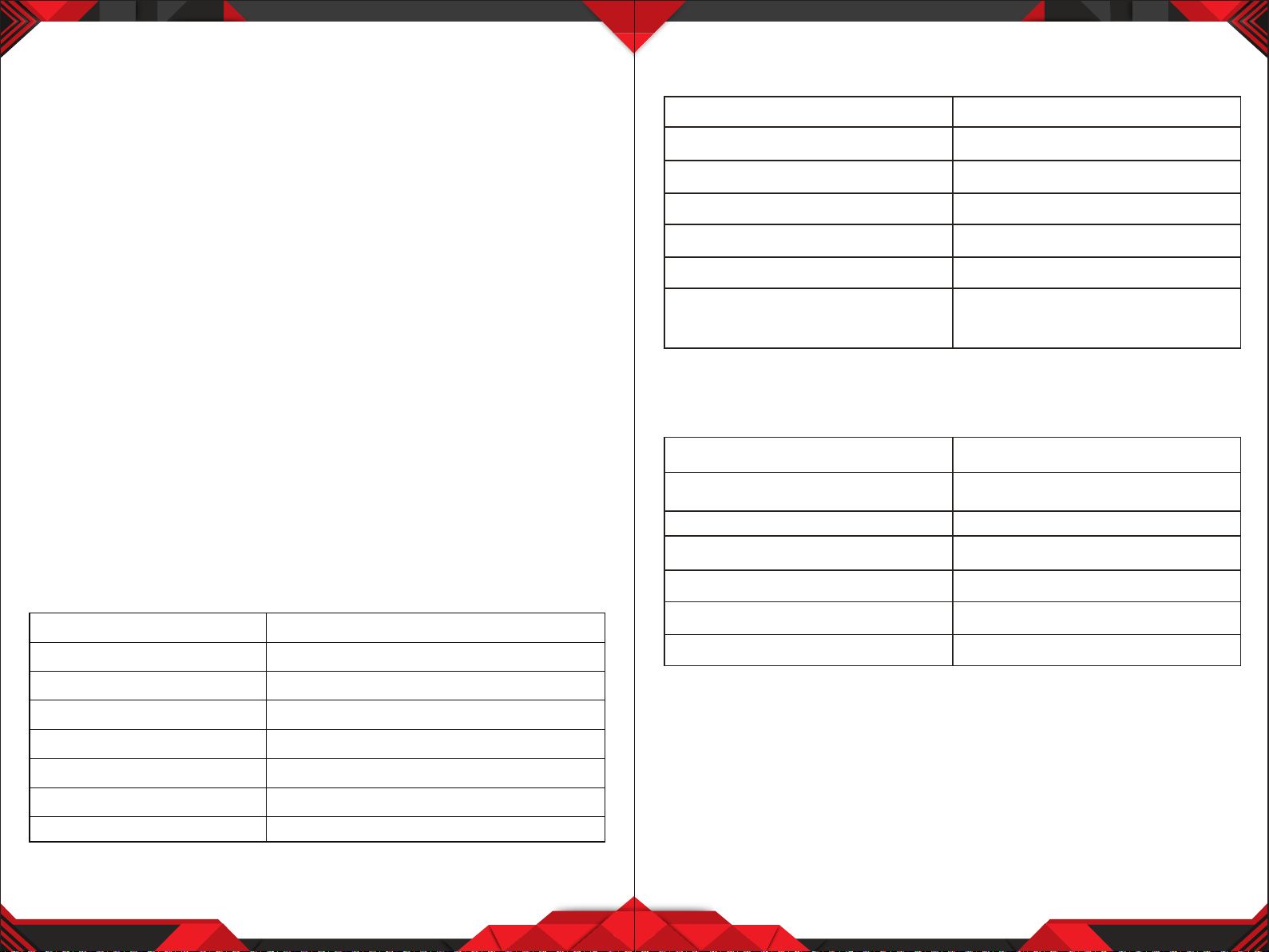
10. TROUBLESHOOTING ----------------------------------------------------------------------------- 10
11. SPECIFICATIONS ----------------------------------------------------------------------------------- 11
SYSTEM COMPOSITION
1. Receiver ------------------------------------------------------------------------------------------------ X1
2. Wireless hand-held or body-pack microphone ---------------------------------------- X2
3. Audio Cable ------------------------------------------------------------------------------------------ X1
4. AC power adapter of special receiver ------------------------------------------------------ X1
5. Battery 1.5V ------------------------------------------------------------------------------------------ X4
6. User guide -------------------------------------------------------------------------------------------- X1
1 2
Please read this manual before using this equipment in order to avoid damage
through incorrect operation and to get the best performance from your
purchase. Please keep and store this instruction booklet in a safe place after
reading it for future reference. This series of professional microphone system
uses a super steady PLL-synthesized control circuit that matches a high
ecient, low consumption discharging technique.
We also apply an independently developed mobile frequency compression
and expanding circuit that is chain linked with image frequency lters and
three time checked noise lters in the receiving unit. Every unit passed strict
tests and quality control by the manufacturer.
FOREWORD
Your new series of wireless system is designed to give you the best of both
sound reinforcement worlds: the freedom of wireless system, and excellent
quality. This manual covers each of the series system: The Vocal Artist-UHF,
and The Headset-UHF.
SYSTEM FEATURES
1. Adopt the PLL-Synlhesized control technique, 8 selectable UHF channels.
2. The UHF frequency range is 573- 597.8MHz, avoiding the frequency
interruption.
3. LCD information display.
4. Double noise squelch operation circuit and system will be higher ecient
and much more steady.
5. Use the dynamic type and Unidirectional cartridge, clear to show the sound.
6. High ecient and low consumption design.
7. Use the high extension antennas, the operating distance will reach 50m.
SYSTEM TYPE
The Vocal Artist-UHF is a hand-held system designed for singers who desire
the high quality of microphones and the freedom of wireless performance.
The Presenter-UHF is a body-pack system designed for public speakers who
prefer an inconspicuous, hands-free lavalier microphone.
The Headset-UHF is a body-pack system designed for users in physically
active applications, who desire the freedom of hand-free microphone.
The Guitarist-UHF is a body-pack system designed for use with electric
guilars, basses, and other electric instruments.

www.PyleUSA.com www.PyleUSA.com
DUAL CHANNEL RECEIVER FEATURES
1. Power Switch: Power ON/OFF the receiver.
2. Power Indicator: Indicate the power ON/OFF.
3. "RF" Signal Indicator: It glows when the Receiver receives RF signal from
Transmitter.
4. "AF" Audio Level Indicator: Indicate the wireless system audio signal level.
5. LCD Information Display: Shows the receiver frequency channel etc.
6. Down Function Button: Sets channel data.
7. Up Function Button: Sets channel data.
8. Volume Knob: Adjust the volume output of receiver.
9. Antenna.
10. XLR Balanced Output Jack: Connect the audio cable from this jack to the
input port of amplier, mixer.
11. 1/4” Audio Output Jack: Connect the audio cable from this jack to the
input port of amplier, mixer.
12. Power jack: Connect the AC/DC adapter to receiver.
3 4
TRANSMITTER FUNCTION & FEATURES
1. Grille: Protects the cartridge and help reducing the breath sounds and wind
noise.
2. LCD Information Display: Show the transmitter frequency channel ect.
3. Down Function Button: Sets channel data.
4. Up Function Button: Sets channel data.
5. Power and Audio Mute Switch.
6. Battery Cover: Open it to install the battery.

www.PyleUSA.com www.PyleUSA.com
1. Power and Audio Mute Switch.
2. Antenna: Transmit the RF signalof transmitter.
3. Belt Clip: Attach the transmitter to the belt.
4. Audio Input Jack: it is suitable for lavaliere system/headset system.
5. Low Battery Indicator: Red light glows when it is lack of power and should
renew the battery.
6. LCD Information Display: Show the transmitter frequency channel etc.
7. Gain Adjusting Volume: Adjust the transmitter audio input gain.
8. State Setting Switch: Set the using state of lavaliere system (L)/headset
system (H).
9. Up Function Button: Sets channel data.
10. Down Function Button: Sets channel data.
SYSTEM CONNECTIONS
1. Receiver Power Connection: Connect the AC adapter into the DC power
connector on the back of the receiver. Plug the AC adapter into a AC 120V
/220V 50Hz outlet.
2. Antenna: Keep the position of antenna at a 45 angle from vertical.
(Shown as below)
5 6
3. Audio Connection: Connect the audio cable from the audio output on the
receiver to the input on your amplier equipment.
BODYPACK TRANSMITTER CONNECTION
1. Lavalier Microphone Connection: Connect the connector of supplied
lavalier microphone to the connecting jack of transmitter (shown as below)
Set the transmitter work state in wireless lavalier system (L).
2. Headset Microphone Connection: Connect the connector of supplied
headset microphone to the connecting jack of transmitter (shown as below)
Set the transmitter work state in wireless headset system (H).

www.PyleUSA.com www.PyleUSA.com
TRANSMITTER BATTERY INSTALLATION
1. Transmitter Battery Installation: Push open the battery cover, insert the
supplied batteries into battery jar matching polarity and cover the battery.
7 8
TROUBLESHOOTING
PROBLEM INDICATOR STATUS SOLUTION
No Sound
No Sound
No Sound
No Sound
No Sound
Sound level diers from
the level of a cabled
Instrument.
Sound level diers from
the level of dierent
guitars
Distortion level increases
gradually
Bursts of noise or other
audible radio signals
present
Momentary loss of
sound as transmitter is
moved around
performing area.
Receiver signal indicators
A/B lights glowing
Receiver signal indicators
A/E lights glowing
Signal indicators A/B
lights ON
Receiver signal
indicator A/B lights OFF
when sound is lost
Red transmitter
indicator is not
ashing
Red receiver POWER
light o
Receiver signal
indicators A/B lights
o. Transmitter and
receiver POWER lights
glowing
Receiver signal
indicators A/B lights
glowing
Red transmitter
indicator is ashing
Slide transmitter POWER ON/OFF switch
to ON position. Make sure battery is
inserted properly, observing battery (+/-).
If the battery is inserted properly, replace
with fresh battery.
Slide transmitter MUTE/ON switch to ON
position
Make sure AC adapter is securely
plugged into electrical outlet and into DC
input connector. Make sure AC electrical
outlet works and supplies proper voltage
Trun up receiver volume control. Conrm
that the output connections from the
receiver to the external equipment are
secure
Conrm transmitter and receiver~
frequency match. Move transmitter
closer to receiver.
Adjust transmitter gain level to
compensate.
Adjust receiver volume as necessary
Readjust transmittergain level to
compensate dierences in guitar outputs
Replace transmitter battery
Identify potential sources of interference
(other RF sources) and turn OFF, remove
or use a wireless system operating on a
dierent frequency
Reposition receiver and perform
walk-through again. If audio dropouts
persist, mark “dead” spot-and avoid them
during performance.
Receiver signal indicators
A/B lights and
transmitter LOW
BATTERY light glowing

www.PyleUSA.com www.PyleUSA.com
9 10
HAND-HELD TRANSMITTER SPECIFICATIONS
BODY-PACK TRANSMITTER SPECIFICATIONS
SYSTEM SPECIFICATIONS
• RF Carrier Frequency Range:
Approximately 523 to 597.8 MHZ (Available frequencies depend on
applicable regulations in country where system is used).
• Operating Range: 50m (approximately 164ft) under typical conditions
• Audio Frequency Response: 100 to 18,000Hz, ±3dB
• THD: <1%
• Mobile state Range: > 100dB
Operating Temperature Range
-20.2°F to 165.2°F (-29°C to 74°C)
NOTE: Battery characteristics may limit this range.
OPTIONAL ACCESSORIES
1/4" to 1/4" Cable (The Guitarist -UHF only)
1/4" to Miniature Connector
1.8 Meter (6ft.) Receiver-Mixer Cable
RECEIVER SPECIFICATION
PowerRequirements
120
V
or
230
V
A
C
adaptor
with
2.
1
mm
femal
e
plug
PowerRequirements 13 -15 VDC nominal,500mA+
Signal/Noise
Ratio
MORETHAN
85dB
BorderUponChannel
Rejection
MORE
THAN
70dB
Image
&SpuriousRejection
MORE
THAN
70dB
AudioOutput
Level
0-
±300mV
Receiving Sensitivity -105dBm
Dimensions
8.5" X 6.7" X 2" inches
Power
Requirements
1.5VAA battery X
2
Nominal Current
Drain
LESS THAN 100mA
Modulation Type
FM
RF
Output
MORE THAN
1
0dBm
Max
Deviation
±70KHz
Spurious
Emission
MORE THAN
55dB
Dimensions
9.8" X 2" X 2" inches
Power
Requirements
1.5VAA battery
X
2
Nominal Current
Drain
LESS THAN 100mA
Modulation
Type
FM
RF
Output
MORE THAN
1
0dBm
Max
Deviation
±70KHz
Spurious
Emission
MORE THAN
55dB
Dimensions
4" X 2.5" X 1" inches
This manual suits for next models
1
Table of contents
Other Pyle Microphone System manuals

Pyle
Pyle PDWM2145 User manual

Pyle
Pyle PDWM1800 User manual

Pyle
Pyle PDWM 4520 User manual

Pyle
Pyle PDWM1950 User manual

Pyle
Pyle PDWM1902 User manual

Pyle
Pyle PDWM3300 User manual

Pyle
Pyle Premier Series PDWM1800 User manual

Pyle
Pyle PDWM2800 User manual

Pyle
Pyle PDWM2700 User manual

Pyle
Pyle PDWM3450 User manual