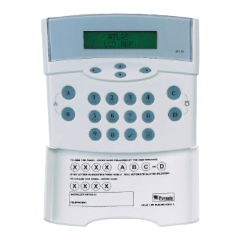
Pyronix ATLAS 8 User manual

Rins171 Issue 6
(
INSTALLATION INSTRUCTIONS
Lcd Remote Keypad
Pyronix Ltd MARCH 00
This Product is approved for use in the
Residential, Commercial and Light Industrial Environment.

Page 2
WARRANTY
This product is sold subject to our standard warranty conditions and is warranted against defects in workmanship for a
period of 2 years. In the interest of continuing improvement of quality, customer care and design, Pyronix reserve the
right to amend specifications without giving prior notice.
A copy of our warranty can be obtained from the above address.
3\URQL[/LPLWHG
3\URQL[+RXVH
%UDLWKZHOO:D\
+HOODE\5RWKHUKDP
64<(1*/$1'
7HO
)D[
7HFKQLFDOKHOSOLQH8.RQO\
HPDLO
H[SRUWVDOHV#S\URQL[FRP
PDUNHWLQJ#S\URQL[FRP
WHFKQLFDOVXSSRUW#S\URQL[FRP
ZHEVLWHZZZS\URQL[FRP
7KLV
LV
D
SUHPLXP
UDWH
OLQH
ZKHUH
FDOOV
DUH
FKDUJHG
DW
S
SHU
PLQXWH
XNVDOHV#S\URQL[FRP

Rins171 Issue 6 Page 3
&217(176
1. INTRODUCTION 5
2.SAFETY 5
3. ACCESS LEVELS 5
3.1 Limited User 5
3.2 Master User 5
3.3 Engineer 5
4. FUNCTIONAL DESCRIPTION 5
4.1 Operating Modes 5
4.2 Entry / Exit Mode 6
5.ZONES 6
5.1 Engineer Programmable Zones 6
6.DIALOUTREPORTING 6
7. FUNCTIONS 7
8. INSTALLATION AND WIRING 11
8.1 Plan View With Cover Removed 11
9. PANEL ASSEMBLY 12
10. POWER CONNECTIONS 14
10.1 Connections 14
10.2 Battery Connections 14
10.3 Bell, Strobe and Extension Speaker Connections 14
10.4 Remote Keypad ’RKP’ Connections 14
10.5 Battery Capacity 15
10.6 End Of Line Resistor 15
10.6.1 Atlas 8 End Of Line Resistor Wiring Diagram 16
10.6.2 Atlas 8 Double Pole Zone Wiring Diagram 16
10.7 Telephone Connections 16
10.8 Powering Up The panel 16
10.9 Atlas Double Pole Wiring Diagram 17
10.10 Atlas End of Line Wiring Diagram 18
11.PROGRAMMING 19
11.1 Factory Defaults 19
11.2 Entering Engineer Mode 20
11.3 Setting Volume Control 20
11.4 Resetting The Non-Volatile Memory (NVM) to Factory Settings 20
11.5 Setting The Panel When Mains Fails 20
11.6 Programming Set Modes 20
11.7 Setting The Alarm Bell Time 20
11.8 Setting Entry Time 21
11.9 Setting Exit Time 21
11.10 Changing The Engineer Code 21
11.11 Programming Options 21
11.11.1 Programmable Output 1 21
11.11.2 Programmable Output 2 21
11.11.3 System Option 1 22
11.11.4 System Option 2 22
11.11.5 System Option 3 22
11.11.6 System Option 4 22
11.11.7 Programmable Re-sets 22
11.12 Central Monitoring Station Telephone Number 23
11.13 Second Telephone Number 23
11.13 Customer Account Code 1 23
11.14 Downloading Access Code 23
11.15 Zone Alarm Reporting Codes 23

Page 4
11.16 Reporting Codes 23
11.16.1 Zone Alarm Reporting Codes 23
11.16.2 Zone Tamper Report Codes 24
11.16.3 System set / unset Reporting Codes 24
11.16.4 User Set Reporting Codes 24
11.16.5 User Unset Reporting Codes 25
11.16.6 Maintenance and Priority Codes 25
11.16.7 Restoral Reporting Codes 25
11.17 Digicom Codes 26
11.18 Keyswitch Set Configuration 26
11.19 Group Reporting Telephone Allocation 26
11.20 Engineer NVM Reset 27
11.21FollowSelect 27
11.22 Exiting Engineer Mode 27
12.SYSTEMFAULTS 28
13. TECHNICAL SPECIFICATION 29
13.1 Power supply 29
13.2 Control PCB 29
13.3 Mechanical 29
13.4 Environmental 29
13.5 Cleaning 29
14. ENGINEER QUICK REFERENCE PROGRAMMING 30
15. COMMUNICATION PROGRAMMING 31
ATLAS 8 SERVICE HISTORY 35
8 ZONE PROGRAMMING LABEL 36

Rins171 Issue 6 Page 5
1 INTRODUCTION
The Atlas 8 is a fully featured intruder alarm control panel, based around a micro-controller with 8 fully programmable
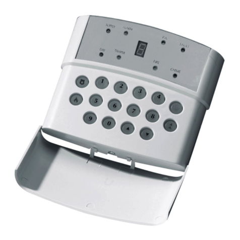
zones. It may be operated via a single Remote Keypad, a maximum of 3 remote keypads (Atlas RKP’s) may be fitted at
convenient points around the premises. Each keypad has an arrangement of 8 LED’s to show the status of the system,
and a 7-segment display to show programming data and events held in the event-log memory.
All features are fully programmable and there are three levels of access to the system.
The Limited User codes allow access to the basic functions needed for everyday Setting and Unsetting of the
system.
The Master User level gives access to all Setting and Unsetting facilities, but also allows the changing of code
numbers and testing of the system.
The Engineer level gives total access to the system including the ability to reconfigure the system and reset the
system event-log memory. The Engineer cannot, however, Unset the system.
2 SAFETY
The 17V a.c. supply to the control panel is connected into the PCB terminal blocks marked 17~. Signal wires to
detectors, etc., should be securely tied together on completion of the installation, to prevent the possibility of a safety
hazard in the event of a wire becoming loose.
This equipment is not suitable for location in bathrooms or damp conditions.
3 ACCESS LEVELS
3.1 Limited User Level Enables: 1. Panel Setting and Unsetting with a unique pass code.
2. Enabling or disabling of the door chime facility.
3. Event log viewing.
3.2 Master User Level Enables: All Limited User facilities.
4. Clearing of event log (if allowed by the Engineer).
5. Omitting zones.
6. Alteration of both Limited and Master User codes.
7. LED / Strobe / Bell / Extension Speaker test facility.
8. Walk test facility for all four Set modes.
9. Programmable output operations.
10. Remote Dial in enabling.
3.3 Engineer Level Enables: a. All Master User facilities except Unsetting.
b. Zone programming for all four Set modes.
c. Bell timer setting.
d. Entry / Exit timer settings.
e. Alteration of Engineer code.
f. Enabling or Disabling of Event log reset by Master user.
g. Programming of communication and programmable output options.
4 FUNCTIONAL DESCRIPTION
4.1 Operating Modes
Day Mode This is the state of the panel when unset. Fire, Personal Attack and Tamper inputs, however,
remain active 24 hours a day. (These are referred to as 24 hour zones).
Day mode is identified by the day text displayed on the top line of the LCD on the keypad.
Set Modes When the panel is set an activation of any Access, Immediate or 24 hour zone will cause an
alarm condition. When an alarm is generated the internal and external sounders will operate for
the length of time programmed and the tone of the internal sounder will be two notes repeated
rapidly. The strobe lamp will also be activated and will continue to operate until the panel is reset.
At the time of setting the control panel, any one of four Set modes can be selected. i.e.
Set A: Whole system set; nobody on premises.
Set B: Upstairs off, Downstairs set.
Set C: Upstairs set, Downstairs off.
Set D: Garage and kitchen off, remainder set.
The above are purely examples. The Engineer has the ability at the programming stage to configure
all the circuits to the customer's exact requirements.

Page 6
4.2 Entry / Exit Mode
Entry When the panel is set and an Entry / Exit zone is triggered the Entry / Exit timer will begin to countdown.
During this period an Entry / Exit tone (single repeated bleep) will be produced by the internal sounder and
any zones which are programmed as Access zones will be ignored.
If either user code is entered before the end of the count down period the panel will return to ‘day’ mode.
If the timer is allowed to elapse before a user code is entered the panel will go into an alarm state. In this
case the system needs to be 'Unset'.
Exit With the panel unset, if a user code is entered the Entry / Exit timer will begin. If all the immediate zones are
clear, then the Entry / Exit tone will be heard. Leave the protected area by the predetermined Entry / Exit route.
As you trigger Access zones the tone will change temporarily to a repeated low tone. When all the zones are
clear, the Entry / Exit tone will continue again until the end of the time-out period. The panel will then be set.
5 ZONES
5.1 Engineer Programmable Zones
Entry / Exit This is a zone which allows limited-time access to the premises in order to Set or Unset the system.
Access This is a zone which, on Setting the panel, allows access to the Entry / Exit zone. However, if the
panel is set and an Access zone is triggered before an Entry / Exit zone then an alarm will be
generated immediately.
Immediate This is a zone, which will, when triggered, wil create an alarm when the panel is set.
Omit If a zone is programmed as an Omitted zone by the Engineer, then it is ignored by the panel. It allows
the user to continue to use the alarm system even if a fault has been discovered on one or more
zones.
Personal Attack Triggering of the Personal Attack (P.A.) zone will always cause a full alarm activation regardless of
whether or not the panel is set. The P.A. zone may be programmed as silent . A silent P.A. activation
will not cause the bell and strobe to operate but the central station will be informed of a P.A. activation.
Tamper The tamper zone may be programmed to give an internal siren or internal / external sounder in day
mode. In Set mode both sounders will operate.
Fire Triggering of the fire zone will activate internal and external sounders. A fire alarm is identified by a
three note rising sound which is easily distinguished from all other tones.
NOTE:
The Fire Zone is intended as an extra feature to the intruder alarm system and must not
be regarded as a total fire protection system.
24 Hour Zone Will cause an instant alarm when the panel is in Set or Unset mode. (Fire, Personal Attack and
Tamper are all 24 hour zones).
Latched Keyswitch
May be programmed to Set the System in one of the Set modes by using a latched mechanism.
Momentary
Keyswitch May be programmed to Set the System in one of the Set modes by momentarily pressing a switch.

Rins171 Issue 6 Page 7
6 DIAL OUT REPORTING
The Atlas 8 has the capability to send messages of alarm status to a Central Receiving Station. Every time the alarm
status changes i.e. Alarm Set / Unset System Fault or Alarm Actuation a message is sent to the CRS informing it of the
status change. This is called Dial Out Reporting. Dial Out Reporting can be configured to Group Reporting which allows
different alarm status changes to be reported to two different locations, 4 groups are available:
Group 1 - Alarms
Group 2 - Set / Unset
Group 3 - Maintenance
Group 4 - 24 Hour call test
This gives the engineer the ability to configure the system to only report condition changes to relevant locations.
i.e. one location could be informed of all status changes (Groups 1 to 4) while a second location could only be informed
of Group 1 conditions.
Confirmed Alarm:This is an extra code which is sent upon two different zones being activated in one set period. It is
used to signal that the alarm condition is less likely to be a false alarm, thereby resulting in a higher level of response.
7 FUNCTIONS
Volume Control This is only accessible when the front cover has been removed and will only affect the volume of any
extension speakers. The volume control is overridden when the panel is in an alarm state.
Chime Chime function applies to ‘day’ mode only and if selected will cause the panel to generate a three-note
sound when an entry/exit zone is triggered. This feature is to inform the occupants of the building that
some one has entered.
Event Log The Atlas 8 control panel incorporates a memory log of the last 30 alarm events and is accessible to
both Users and the Engineer. It will record Fire, Intruder, Personal Attack and Tamper alarms and also
show if any of the 8 alarm zones have been triggered or omitted. The Engineer can set the clearing of
the log for either Engineer-only or Master User and Engineer.
Auto Re-Set After an alarm the panel will automatically reset itself when the bell timer has expired.
Any zones, which still remain triggered at that time, will be omitted automatically.
Walk test The walk test function allows each of the Set modes to be checked in order to verify that all the
intruder detectors on the alarm system are functioning correctly. When undergoing a walk test the
Engineer or Master User can choose which of the Set-modes he wishes to test. Any zones used in
that Set-mode will cause a chime at the RKP or extension speaker if they are triggered.
Keypress Timeout
There is a 60 second keypress timeout facility. If a key is not pressed within 60 seconds of the last
keypress the keypress buffer is cleared.
Duress This feature allows the user to either Set or Unset the alarm with the last two digits of the code
reversed, this will then send a Duress Code to the Central Receiving Station.
The panel will appear normal when the duress code is active.
Programmable
Outputs (PGM) There are 2 programmable outputs which may be programmed for any of the following 7 options:
Remote LED Enable: This option will allow the PIR LEDs to be enabled during Walk test mode if they
have been originally disabled by removing the link pin. This option will only work if the PIR has a
remote LED enable facility.
Latch Memory: This feature is useful when more than one detector is connected to a single zone.
When the panel is set the LEDs of any triggered detector on this zone will latch causing their LEDs
to flash on and off when the panel is disarmed. This feature will only work if the PIR has a Latch
Memory facility.
5 Seconds Switch Output: This option will allow the programmable output to act as a momentary
switch. This could be used for example to unlock an external electronic door.
Panel Set / Unset Switch Output: By using this option the programmable output will switch as the
panel is set and disarmed. This may be used for example to electronically lock a door as the panel is
set and unlock it when the panel is unset.
Follow Zone: This option will allow the programmable output to switch on and off as the
programmed zone is entered and exited.
Follow Line Fail: This option will allow the programmable output to switch on when a line fail
occurs and switch off when the line is active again.
Follow Kiss Off: This option will allow the programmable output to switch on for a few seconds
when a communication kiss off has been successfully completed.
Page 8
System Option 1. The system may be configured for use with the following:
Double Pole Zones: This is a normally closed zone configuration without end of line resistor.
Double End of Line Zones:This configuration uses end of line resistors which allow both zone and
tamper circuits on the same zone connection.
User Log Reset Enable: This option allows the user to reset the system log by entering
User Log Reset Disable: By selecting this option only the engineer has the ability to reset the system
log.
Tone Dial: Select this option for telephone exchanges using tone dial technology.
Pulse Dial: Select this option for telephone exchanges using pulse dial technology.
Internal & External Sounders
On Tamper Activation: This option will cause both internal and external sounders to activate on
a tamper alarm when the panel is in day mode.
Internal Sounder Only On
Tamper Activation: This option will cause only the internal sounder to activate upon a tamper
alarm when the panel is in day mode.
System Option 2. The system may be configured for use with the following:
7 Day Test Dial: Dials the Central Monitoring Station every 7 days.
24 Hour Test Dial: Dials the Central Monitoring Station every 24 hours.
Dial In: This option will allow the Atlas 8 to respond to an incoming call in answer
machine compatible mode.
Answer machine compatible mode: This provides a way of using the Atlas
on the same line as an answering machine. The default setting is AMC on.
To remotely access the Atlas in AMC mode dial in and wait for a single
ring, then hang up and wait for at least 10 seconds, but no more than 40,
then dial back in. The Atlas will now answer instantly.
No Dial In: This option will cause the Atlas 8 to ignore incoming calls. The master user
may generate a one hour time window to allow up/downloading by using
the function. If this option is selected - this will answer on a single ring.
Wide handshake filters: Gives a greater chance of the handshake from central station being
recognised, use only if the panel does not transmit data after the correct
handshake sequence has been transmitted by the central station.
Standard handshake This setting is the default and will more reliably detect the correct
filters: handshake
Silent P.A. Zones: The P.A. zone activation will not generate internal or external sounders if
this option is selected. Dial out will occur however if the panel has been
programmed to do so.
Audible P.A. Zones: The Personal Attack zone activation will cause both internal and external
sounders to operate. Dial out will also occur if the panel has been
programmed to do so.
System Option 3. The system may be configured for use with the following:
Engineer Code Lock
N.V.M Reset: This option allows the control panel programmable settings to be reverted
back to factory default when in Engineer mode only.
Engineer Power Up
N.V.M Reset: This allows the control panel programmable settings to be reverted back to
factory default when in User Mode.

Rins171 Issue 6 Page 9
Display Open Zones: When enabled and the panel is unset, any entry / exit, access or
immediate zone, when activated will be displayed on the keypad.
Alarm In Line Fail: When the panel is set, if a line fail occurs the internal and external
alarms will activate.
Disable Telephone Line
Monitoring: This option when selected, will suppress system fault 6.
Programmable Re-sets:
The number of control panel rearms maybe programmed as follows:
a) from 1 to 9 to give up to 9 re-arms
or b) continuous re-Setting after an alarm activation.
Central Monitoring Station Telephone Number:
This is the telephone number of the central monitoring Station which, if required, the Atlas 8 will dial to
during an alarm activation.
Central Monitoring Station Second Telephone Number:
This is an alternative number which will be used by the Atlas 8 if the first telephone line is busy.
If after four attempts connection with the first number fails then this number will be dialed.
Customer Account Code:
This is a three or four digit number given to the installation engineer by the central monitoring station.
The number identifies the customer site when the Atlas 8 dials out during an alarm activation.
The upper HEX digits (B to F) can be used for reporting codes.
Downloading Access Code:
This is a four digit access code required by the alarm company in order to access the Atlas 8 during
an uploading or downloading operation.
Reporting Codes:
These are unique two digit or single digit numbers used by the central monitoring station to identify the
zone causing an alarm activation and to give information on the status of the Atlas 8. These codes are
issued by the central monitoring station and are dialed out by the Atlas 8 when programmed to do so.
The upper HEX digits (B to F) can be used for reporting codes.
Restoral Reporting Codes:
After an alarm activation one of two restoral reporting codes maybe logged.
User Code Restoral:
This code will be logged if the master user code or limited user code is used to Unset the panel after
an alarm activation.
Bell Timeout Restoral:
If after the external sounder has timed out the panel is automatically re-set, the bell timeout restoral
code will be logged.
Battery Restoral: This code will be reported when a battery fault is restored after a failure.
Mains Restoral: This code will be transmitted upon restoral of a.c. mains after a failure.
Digicom Codes: The Atlas 8 may be programmed to output its communicator codes in one of four different formats.
SIA DTMF format is the default. Check with your central monitoring station for the required format.
Keyswitch Set Configuration:
Any of the Atlas 8 alarm zones may be programmed as a keyswitch zone. The keyswitch may be
configured to Set the panel as Set A, B, C or D. (see programming section for details).

Page 10
System Option 4
Bell Squawk-
Upon expiry of the exit time, if the panel sets OK the bell will emit a short duration of sound. It will also
emit a short duration of sound upon disarming.
Default value - OFF.
Bell Time Minutes/Seconds-
This option allows for very short bell durations.
Default value - Minutes.
AC Fail Delay
This option delays the display and transmission of AC faults. Generally used in areas where there is an
unstable mains supply.
Default value - 0 Minutes

Rins171 Issue 6 Page 11
8 INSTALLATION AND WIRING
Before beginning any installation work read through this section carefully. Plan out the various areas and degrees of
protection required from each zone. It is important to decide which type each zone should be if selective sets are to be
used. Work out the cable routes avoiding mains cabling and consider the chosen position for the control panel.
8.1 Plan View With Cover Removed

Page 12
9 PANEL ASSEMBLY
9.1 Steel Panel Assembly
Take off the front cover and remove the cardboard packaging containing the control panel and PCB. Push in the PCB
support posts from the rear of the panel as shown.
If required assemble the tamper switch from the optional kit of parts as indicated.
If necessary place the transformer and fasten into position using the screws supplied with the transformer kit.

Rins171 Issue 6 Page 13
Hang the control panel base onto the wall with the central mounting hole using one of the screws and plugs from the
screw pack. If possible use a spirit level or some other means to position the control panel squarely then drill two more
holes into the wall to locate the other two screws and plugs.
Finally place the PCB onto its supports.

Page 14
10 POWER CONNECTIONS
10.1 Connections
The Atlas 8 requires a supply of 17V a.c. from the power supply unit or transformer, with a current capacity of 1 amp.
Connect the 17V current to the terminals marked 17~ on the PCB.
17V a.c
10.2 Battery Connection
In order for the Atlas 8 to operate if the mains power is cut a battery back-up is required. Refer to 10.5 for battery
specifications. Connect the battery to the terminals marked +BAT- on the PCB.
Battery Positive (+) Battery Ne
g
ative (-)
10.3 Bell, Strobe and Extension Speaker Connections
Bell Positive (+)
Bell Trigger
Strobe Positive (+)
Strobe Ne
g
ative (-)
Speaker Positive (+)
Speaker Ne
g
ative (-)
NOTE:
The bell Negative (-) should be returned to the BAT (-) connection on the PCB.
The bell tamper must be connected to a tamper zone or connected as end of line zone.
10.4 Remote Keypad ‘RKP’ Connections
Keypad Data
Keypad Positive (+) Keypad Negative (-)
If more than one keypad is to be used, additional keypads can be wired in either daisy chain or star configuration.
The RKP tamper must be connected to a tamper zone or connected as end of line zone.

Rins171 Issue 6 Page 15
10.5 Battery Capacity
It is recommended that the rechargeable battery used with the Atlas 8 control panel should be capable of powering the
alarm system for a minimum of 8 hours, and that this time period should include 20 minutes of bell/strobe operation.
The minimum battery capacity should be calculated from the current consumption of the individual system components.
A typical example based on the following individual parts is shown below:
Non alarm current for control panel (7hrs 40min) : 130mA (0.130 A)
Steady state current for detectors : 120mA (0.120 A)
(e.g. 8 x 15mA for 8 hours - Pyronix PIRs)
Typical standby current for external sounder : 50mA (0.050 A)
(e.g. Self Actuating Bell for 8 hours)
Typical on state current for external sounder (20 mins) : 350mA (0.35 A)
Alarm state current for control panel (20 mins) : 130mA (0.13 A)
Typical current for external strobe (8 hours) : 150mA (0.15 A)
Alarm condition for 20 mins (0.333 hrs)
Alarm state current for control panel : 0.130
8 detectors @15mA : 0.120
External sounder : 0.350
External strobe : 0.150
Standby current for external sounder : 0.050
Single remote keypad : 0.015
Required capacity for alarm condition = 0.815 x 0.333 = 0.271 Ahrs
Capacity required for standby 7hrs 40 mins (7.67 hrs)
Non alarm current for control panel : 0.130
8 detectors @ 15mA : 0.120
External strobe : 0.150
Standby for external sounder : 0.050
Single Remote keypad : 0.015
Required capacity for standby condition = 0.465 x 7.67 = 3.57 Ahrs
Total minimum required battery capacity = 0.271 + 3.57 = 3.84 Ahrs
For this example it is recommended that you use a battery of not less than 6 AH.
10.6 End of line resistors
When a Sensor, and tamper are wired into the same zone this is called an End of Line Zone (EOL). The Atlas 8 panel
uses resistors on all of its end of line zones. Two resistor values are used, these are 2K2 and 4K7.
To identify the two resistors, coloured bands on the body are used. These are as follows:
2K2 4K7
Fourth Band
Red Red
Red
Fourth Band
Yellow
Violet
Red
Any unused zones should NOT be left open circuit. These should have a 2K2 resistor inserted, Refer to diagram 10.6.1,
page 17.
NOTE:
when the panel and sensors are wired using end of line resistors, to enable the zone to detect alarm and tamper,
the system must be configured in System Option 1. Refer to Page 23.
10.6.1 Atlas 8 End Of Line Resistor Wiring Diagram.

Page 16
10.6.2 Atlas 8 Double Pole Zone Wiring Diagram.
Wiring two or more sensors with end of line resistors to a single zone.
NOTE:
only one 2K2 resistor should be used per zone
. The 2K2 resistor should be installed into the last detector in
series to protect all the zone tamper wiring.
Up to ten sensors or door contacts may be wired on each zone.
10.7 Telephone Connections
T - 1 R - 1 TIP RING
10.8 Powering Up Your Panel / RKP
a. Connect the battery leads to the control panel. (+BAT-). The red lead should be connected to "+" terminal
and the black lead to "-" terminal.
b. Push on the spade connectors to connect the battery
c. Switch on the AC supply. The supply LED will be on. Now proceed to Section 11 "Programming".

Rins171 Issue 6 Page 17
2
3
7
,
2
1
$
/
6
,
5
(
1
9
0
$
*
1
(
7
,
&
&
2
1
7
$
&
7
H
J
(
;
,
7
(
1
7
5
<
'
2
2
5
a
%
$7/$6&21752/3$1(/
7
7
1
&
7
7
1
&
7
7
1
&
H
J
,
0
0
(
'
,
$
7
(
=
2
1
(
/
,
9
,
1
*
5
2
2
0
%$77(5< 5(&+$5*($%/(
3<521,;
3,5
7
$
0
3
(
5
$
/
$
5
0
6
8
3
3
/
<
3<521,;
3,5
%
%
%7
7)
67%
%$
'
(
&
,
%
(
/
/
.
.
$/$50
63$5(
1&
.
.
.
.
.
.
.
(
6
(
(
3
$
*
(
&
.
.
.
H
J
$
&
&
(
6
6
=
2
1
(
+
$
/
/
7
$
0
3
(
5
$
/
$
5
0
6
8
3
3
/
<
(
;
7
(
1
6
,
2
1
6
3
(
$
.
(
5
2
3
7
,
2
1
$
/
%
$
7
7
(
5
<
.
.
.
'
.
7
.
7
5
5
(
6
7
2
)
7
(
/
(
3
+
2
1
(
6
<
6
7
(
0.
(
<
3
$
'
7
$
0
3
(
5
&
2
1
1
(
&
7
,
2
1
6
6
+
2
8
/
'
%
(
:
,
5
(
'
7
2
$
=
2
1
(
3
5
2
*
5
$
0
0
(
'
)
2
5
7
$
0
3
(
5
7
(
/
(
3
+
2
1
(
1
(
7
:
2
5
.
5
.
3
.
L
ine in

Page 18
a
%
$7/$6&21752/3$1(/
7
7
1
&
7
7
1
&
%$77(5< 5(&+$5*($%/(
3<521,;
3,5 3<521,;
3,5
%
%
%7
7)
67%
%$
'
(
&
,
%
(
/
/
%
$
7
7
(
5
<
.
.
.
'
.
7
.
7
5
5
(
6
7
2
)
7
(
/
(
3
+
2
1
(
6
<
6
7
(
0.
(
<
3
$
'
7
$
0
3
(
5
&
2
1
1
(
&
7
,
2
1
6
6
+
2
8
/
'
%
(
:
,
5
(
'
7
2
$
=
2
1
(
3
5
2
*
5
$
0
0
(
'
)
2
5
7
$
0
3
(
5
7
(
/
(
3
+
2
1
(
1
(
7
:
2
5
.
5
.
3
.
(
6
(
(
3
$
*
(
&
H
J
$
&
&
(
6
6
=
2
1
(
+
$
/
/
H
J
,
0
0
(
'
,
$
7
(
=
2
1
(
/
,
9
,
1
*
5
2
2
0
(
;
7
(
1
6
,
2
1
6
3
(
$
.
(
5
2
3
7
,
2
1
$
/
2
3
7
,
2
1
$
/
6
,
5
(
1
9
0
$
*
1
(
7
,
&
&
2
1
7
$
&
7
H
J
(
;
,
7
(
1
7
5
<
'
2
2
5
$/$50
63$5(
1&
7
$
0
3
(
5
$
/
$
5
0
6
8
3
3
/
<
7
$
0
3
(
5
$
/
$
5
0
6
8
3
3
/
<
L
ine in

Rins171 Issue 6 Page 19
11 PROGRAMMING
11.1 Factory Defaults
The panel is preprogrammed to the factory settings shown below.
Master User code : 1234 (0000-9999)
Limited User code : 5678 (0000-9999)
Engineer code : 9999 (0000-9999)
Bell timer : 20 minutes (programmable 2 to 20 mins)
Entry : 30 seconds (programmable 2 to 255 secs)
Exit : 30 seconds (programmable 2 to 255 secs)
Event log : Engineer reset of log
Downloading access code : 1234
Group reporting : Group1=1, Group2=1, Group3=1
Dial in : Enabled
Zones : End Of Line Resistor
Programmable Outputs : Off
System Option 1 : End Of Line Zone
User Log Reset Disabled
Tone Dial
Internal Sounder Only On Tamper Activation
System Option 2 : 24 Hour Test Dial
DialIn
Spare
Audible PA
System Option 3 : Power Down NVM Reset
Spare
Spare
Spare
Re-sets : Continuous
The zone types are factory set as follows.
Zone Number
1 2 3 4 5 6 7 8
Set A (QWU\H[LW DFFHVV ,PPHGLDWH LPPHGLDWH LPPHGLDWH LPPHGLDWH LPPHGLDWH LPPHGLDWH
Set B (QWU\H[LW DFFHVV ,PPHGLDWH LPPHGLDWH LPPHGLDWH LPPHGLDWH LPPHGLDWH LPPHGLDWH
Set C (QWU\H[LW DFFHVV ,PPHGLDWH LPPHGLDWH LPPHGLDWH LPPHGLDWH LPPHGLDWH LPPHGLDWH
Set D (QWU\H[LW DFFHVV ,PPHGLDWH LPPHGLDWH LPPHGLDWH LPPHGLDWH LPPHGLDWH LPPHGLDWH

Page 20
11.2 Entering Engineer Mode
To enter the Engineer Mode.
Enter (Engineer Code, factory default to 9999)
Whilst in Engineer mode, you are able to remove any covers without creating a tamper alarm.
11.3 Setting Volume Control (Extension speaker only)
This volume is controlled via the adjustable volume pot on the main processor board.
1. Remove lid.
2. Set volume pot to desired volume
3. Depress a number digit on the keypad to check desired volume has been reached.
4. Replace cover.
In an alarm condition the volume control is overridden and the speakers will operate at full volume.
NOTE:
Each RKP has its own volume control pot.
11.4 Resetting the Non Volatile Memory (NVM) to Factory Settings
The panel may be programmed as power up NVM reset or engineer only NVM reset.
Power Up NVM Reset
If the panel is configured by the engineer to allow the reset of the NVM back to factory settings by powering up the
system with the NVM reset pins shorted together.
Locate the NVM reset pins on the PCB, using the link pin provided connect the two pins together. Power down the
system (mains and battery). Restore power and remove the link. The system is now back to factory default settings.
Engineer Only NVM Reset
If the panel is configured for Engineer Only NVM Reset, the panel can only be reset to factory defaults if the Engineers
code is known.
Enter the engineer mode. Use the link supplied to connect the NVM reset pins together and enter on the
key pad, remove the link. The system is now back to factory default settings.
11.5 Setting the Panel when Mains Fails
Under normal operation the panel will indicate a fault condition if the AC supply is disconnected. It will still be possible to
Set and Unset the control panel during a mains fail and no further action is required.
Full functionality of the control panel is available during mains fail.
11.6 Programming Set Modes.
Any zone may be programmed to be any one of the following:
(QWU\([LW $FFHVV LPPHGLDWH RPLW PRPHQWDU\NH\ ODWFKHGNH\
WDPSHU SHUVRQDODWWDFN KRXUILUH
The attribute for each zone is changed by pressing or until the required attribute appears in the display.
When the display shows the required attribute press the key to store the zone attribute. If the required attribute is
already shown press the key to go to the next zone.
NOTE:
On pressing
after selecting the attribute for zone 8, the programme will be stored automatically.
To programme Set A enter , to programme Set B enter
to programme Set C enter and to programme Set D enter .
Should you wish to view any zone status within a Set mode use the same procedure, but do not scroll the keys.
11.7 Setting the Alarm Bell Time
To adjust the alarm bell cut off time. Enter
followed by the required time in minutes ( to minutes) followed by to accept.
Incorrect entry gives an audible error tone and correct entry gives three bleeps.
The alarm bell cut off time for the Atlas 8 is factory set to 20 minutes.
Table of contents
Other Pyronix Keypad manuals

Pyronix
Pyronix BUMBT!8 User manual

Pyronix
Pyronix STERLING 10 User manual

Pyronix
Pyronix ATLAS 4 User manual

Pyronix
Pyronix MATRIX User manual

Pyronix
Pyronix EURO mini EUR-068 User manual

Pyronix
Pyronix EURO mini User manual

Pyronix
Pyronix HIKVISION LEDP/R-WE User manual

Pyronix
Pyronix ATLAS 4 User manual

Pyronix
Pyronix STERLING 10 User manual

Pyronix
Pyronix PCX 162i Operating instructions