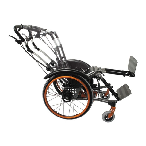
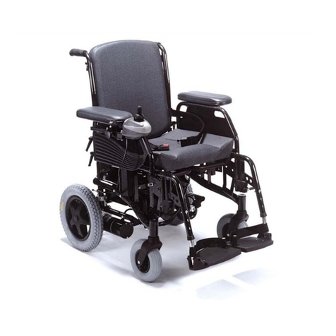
Q'STRAINT QLK-150 User manual

INSTALLATION INSTRUCTIONS
Q5-1150-KITE
READ ALL INSTRUCTIONS PRIOR TO INSTALLATION
• This is a comprehensive step-by-step instrucon guide on how to install the QLK-150 KITE Wheelchair Bracket.
• Make sure to read, understand and follow all these instrucons.
• To address any quesons contact the nearest Q’Straint® oce.
• All deviaons and alteraons from these instrucons MUST be reported to both your supervisor and Q’Straint®.
• For installaon of the QLK Docking system, please refer to the separate Installaon Instrucons and the Use and Care Manual.
IMPORTANT SAFEGUARDS AND WARNINGS
SAVE THESE INSTRUCTIONS
• All equipment and components MUST be installed and serviced
by an experienced and trained technician.
• The QLK-150 Wheelchair Docking System complies with all
applicable requirements of ADA, FMVSS, CMVSS, SAE J2249,
CSA Z604, AS2942, ISO 10542-1 and ANSI/RESNA WC-4
SECTION 18.
• This System is a complete integrated system, do not alter or
modify it in any way and do not interchange or substute any
components. Any deviaon from these recommendaons is the
responsibility of the installer.
• The QLK-150 Docking System, bracket and its components
MUST be regularly inspected, cleaned and maintained.
• Do NOT aempt to repair, adjust, or modify any component(s) of
the QLK-150 system or bracket without consulng a Q’Straint®
representave.
• The QLK-150 Wheelchair Docking System should not be
operated by anyone who does not have full comprehension of
how the System works or if the System is not working properly.
• The QLK-150 Wheelchair Docking System, bracket and all
system components including oor and wall anchorages MUST
be replaced aer a vehicle collision
• The QLK-150 Wheelchair Docking System MUST be installed
with a compliant occupant restraint system (shoulder and lap
belt).
• Broken and worn components MUST be replaced.
• All damages and defects MUST be reported to both your
supervisor and Q’Straint®.
• Only use Q’Straint® components with this system, including
hardware and wheelchair interface bracket unless otherwise
stated.
• Q’Straint wheelchair brackets and QLK docking staon have
been designed and tested as a system, for use with specic
wheelchairs.
• Q’Straint supplies all the components/hardware required to
install the system so the conguraon is the same as that tested
and set out in the individual installaon instrucons.
• Occasionally, wheelchairs may have addional components
installed which are not detailed in our installaon instrucons
and which may need to be temporarily removed in order to
gain access to xing holes or support frames to enable the
aachment of the wheelchair bracket.
• It is the responsibility of the installer to ensure that all such
wheelchair component(s) are put back in their original locaon
using the original xings or xing of the same size and grade.
• Each wheelchair should be test driven aer tment of the
bracket, to ensure it is funconing correctly.
2
TABLE OF CONTENTS
WARNINGS ...................................................................................................2
COMPONENT STRUCTURE.....................................................................2
EQUIPMENT CHECKLIST .........................................................................3
COMPONENT CHECKLIST...................................................................35
INSTALLATION PROCEDURE..................................................................6
STEP 1: REMOVE REAR PANEL...............................................................6
STEP 2: UNSCREW BOSS..........................................................................6
STEP 3: REMOVE BATTERIES ..................................................................6
STEP 4: INSTALL RIGHT HAND ARM ...................................................6
STEP 5: INSTALL DISC...............................................................................7
STEP 6: INSTALL LEFT HAND ARM ......................................................7
STEP 7: INSTALL DISC................................................................................7
STEP 8: REMOVE FRONT PANEL ...........................................................8
STEP 9: OFFER UP SUPPORT BAR ........................................................8
STEP 10: INSERT HARDWARE ................................................................8
STEP 11: ATTACH SIDE BRACKET.........................................................8
STEP 12: TIGHTEN BOLTS.........................................................................8
STEP 13: FIT DOCKING BOLT..................................................................8
STEP 14: REFIT FRONT PANEL................................................................9
STEP 15: REPLACE BATTERIES................................................................9
STEP 16: REPLACE BATTERY RETAINER..............................................9
STEP 17: REPLACE REAR PLASTIC PANEL..........................................9
STEP 18: INSTALL QLK DOCKING SYSTEM........................................9
STEP 19: ALIGNMENT AND ADJUSTMENT........................................9
COMPONENT STRUCTURE
QE-9051
Q04S153 QC03003Q080034
QE-9050 Q5-1150-KITEQ03BR007
Kite Complete QLK Kit
Kite Complete Bracket
Kit
QLK Kit QLK 2" Flange
Kite Bracket Kit Kite Hardware Kit Kite Installaon Instrucons

3
EQUIPMENT CHECKLIST
EQUIPMENT QT Y.
SIZE
Medium
Strength
Threadlock
N/A 1
Socket
Allen Key
13mm
6mm
1
1
COMPONENT CHECKLIST
PART# AND DESCRIPTION QT Y.
IMAGE
Q03BR007
Kite Bracket Kit 1
QE-9050
Kite Hardware Kite 1
ITEM
Bracket kit Q080034 is to be used with Q04S153 and QC03003. Complete kit is part number QE-9051

4
PART# AND DESCRIPTION QT Y.
IMAGE
Q03C0060
Kite Base Welded Assembly 1
Q03C0067
Kite Side Arm 1 Welded
Assembly
Q03C0074
Kite Arm Outer Disc
Q03C0075
Kite Back Support
Q03C0072
Kite Side Arm 2 Welded
Assembly
1
1
2
1
ITEM
1
2
3
5
4
Within Kit Q03BR007:

5
PART# AND DESCRIPTION QT Y.
IMAGE
QE9-8109
M8 Nylock Nut 10
QE9-5102
M8 x30mm Cap Head
QE9-8107
M8 Plain Nut
QE9-8108
M8 Flat Washer
QE9-8115
M8 x 25mm Socket Cap
Head
20
2
2
10
ITEM
6
7
8
10
9
Within Kit QE-9050:
QE9-8119
38mm Domed Head Docking Bolt 1
11

6
1
2
Step 1: Remove Rear Panel
Remove rear plastic panelling by unscrewing 2 x
threaded bosses, as shown in Fig.1 .
Retain all and keep to one side.
Step 2: Unscrew boss
Unscrew 1 x threaded boss on rear steel panel, as
shown in Fig.2 . This rear panel serves as a battery re-
tainer and mounting surface for electronics
Keep the threaded boss to one side.
Carefully pivot panel downwards, ensuring not to dis-
turb any connections.
Step 3: Remove batteries
Disconnect and remove batteries from the battery
tray, as shown in Fig.3
Step 4: Install Right hand arm
Select item 2 Q03C0067 – Right hand arm, as shown
in Fig.4a, and insert item 8 QE9-8107 - M8 plain nut
into hexagonal recess, as shown in Fig.4b.
Carefully slide the component in between the bat-
tery tray and the rear anti-tipping bracket, as shown
in Fig.4c, ensuring the nut remains in place.
A little leverage or lubricant may be required to allow
the component to be positioned.
The circular boss, as shown in Fig.4d, should click into
place engaging with the mating hole in the anti-tip-
ping backet.
3
4
Fig.1
Fig.2
Fig.3
Fig.4a Fig.4b
Fig.4

7
5
6
Step 5: Install disc
Using item number 3 Q03C0074 - circular disc
along with item 7 QE9-5102 - M8 x 30mm cap head
loosely secure the side arm, as shown in Fig.5, adding
a drop of medium strength thread lock to the end of
the thread.
Do not tighten at this stage but be aware that you
have a limited time before the bolts must be tight-
ened before it sets.
Step 6: Install Left hand arm
Select item 5 Q03C0072 – Left hand arm, as shown
in Fig.6a, and insert item 8 QE9-8107 - M8 plain nut
into hexagonal recess, as shown in Fig.6b.
Carefully slide the component in between the bat-
tery tray and the rear anti-tipping bracket, as shown
in Fig.6c, ensuring the nut remains in place.
A little leverage or lubricant may be required to allow
the component to be positioned.
The circular boss, as shown in Fig.6d, should click into
place engaging with the mating hole in the anti-tip-
ping backet.
Step 7: Install disc
Using item number 3 Q03C0074 - circular disc
along with item 7 QE9-5102 - M8 x 30mm cap head
loosely secure the side arm, as shown in Fig.7a, add-
ing a drop of medium strength thread lock to the end
of the thread.
Do not tighten at this stage but be aware that you
have a limited time before the bolts must be tight-
ened before it sets.
Both arms are now installed, as shown in Fig.7b.
Fig.5
Fig.6
Fig.6a Fig.6b
Fig.6c Fig.6d
Fig.4
Fig.4c Fig.4d
4

8
Step 8: Remove Front Panel
Loosen the retaining stud on the front of the battery
tray, as shown in Fig.8. This will allow the plastic pan-
elling to be free.
Step 9: Oer up support bar
Select item 4 Q03C0075 – Kite Back Support and
insert into the front of the battery tray, as shown in
Fig.9.
This can either be inserted sideways or through the
back of the chair through the gap where the batteries
were.
The loosening of the plastic panel will aid the tment
of this component.
Step 10: Insert hardware
Now connect the above 3 components by using 4 x
item 10 QE9-8115 M8 x 25 bolts, 8 x item 9 QE9-
8108 washer and 4 x item 10 QE9-8115 - M8 nuts,
as shown in Fig.10a and Fig.10b. Again, do not tight-
en at this stage.
Step 11: Attach side brackets
Select item 1 Q03C0060 - Kite Base Welded Assem-
bly and oer up to the side brackets, ensuring the
correct orientation, as shown in Fig.11.
Use 6 x item 10 QE9-8115 - M8 x 25 Cap head and
12 x item 6 QE9-8109 - M8 nuts to retain the plate.
These can be fully tightened now using a 13mm sock-
et and 6mm allen key.
Step 12: Tighten bolts
Fully tighten all other bolts using 13mm socket and
6mm allen key.
Step 13: Fit docking bolt
Fit item 11 QE9-8119 5/8” – 11 Docking Bolt
through item 1 Q03C0060 - Kite Base Welded As-
sembly at the desired height
8
9
10
Fig.8
Fig.9
Fig.10
Fig.10a Fig.10b
7
Fig.7
Fig.7a Fig.7b

9
Step 14: Ret front panel
Replace front plastic panel as shown in Fig.14.
Step 15: Replace batteries
Replace batteries and reconnect.
Step 16: Replace battery retainer
Re-attach the rear pivoting battery retainer, and se-
cure using existing xings.
Step 17: Replace rear plastic panel
Re-attach the rear plastic panelling and secure using
existing xings.
Step 18: Install QLK Docking System
Install QLK docking system Q04S153 QLK 150 Kit
and QC03003 QLK 150 2” Flange as per QLK 150 in-
structions: Q5-1150-QLK150 and Q5-1161-QLK150.
These instructions are provided with the QLK 150
docking station Kit Q04S153.
Step 19: Alignment and Adjustment
Align the wheelchair with the QLK base.
Make any adjustments to the docking bolt height as
required.
Refer to Step 13 for the adjustment procedure for the
docking bolt.
14
Fig.14
11
Fig.11

Q5-1150-KITE Rev 1
www.qstraint.com
© 2019 Q’Straint®. All Rights Reserved.
Q’Straint® and Q’Straint® logo are registered trademarks of Q’Straint®, Inc. QLK is a trademark of Q’Straint®, Inc. Products menoned herein are for idencaon purposes
only and may be registered trademarks, trademarks and patents of their respecve companies. All other brand names, trademarks, registered trademarks and patents are the
property of their respecve owners.
These instrucons contain the most current informaon at the me of prinng. Q’Straint® reserves the right to modify systems, components and content without noce.
FOR TECHNICAL SUPPORT OR TO FIND YOUR NEAREST AUTHORIZED DEALER:
Q’STRAINT EUROPE
72-76 John Wilson Business Park
Whitstable, Kent, CT5 3QT
United Kingdom
Tel: +44 (0)1227 773035
Fax: +44 (0)1227 770035
Email: inf[email protected]
Q’STRAINT AMERICA
4031 NE 12th Terrace
Oakland Park, FL 33334
Tel: 800-987-9987
Fax: 954-986-0021
Email: qstraint@qstraint.com
Q’STRAINT AUSTRALIA
Tramanco Pty Ltd.
21 Shoebury Street,
Rocklea, Australia, QLD. 4106
Tel: +61 7 3892 2311
Fax: +61 7 3892 1819
Email: inf[email protected]
Other manuals for QLK-150
7
This manual suits for next models
1
Table of contents
Other Q'STRAINT Wheelchair manuals

Q'STRAINT
Q'STRAINT QLK-150 User manual

Q'STRAINT
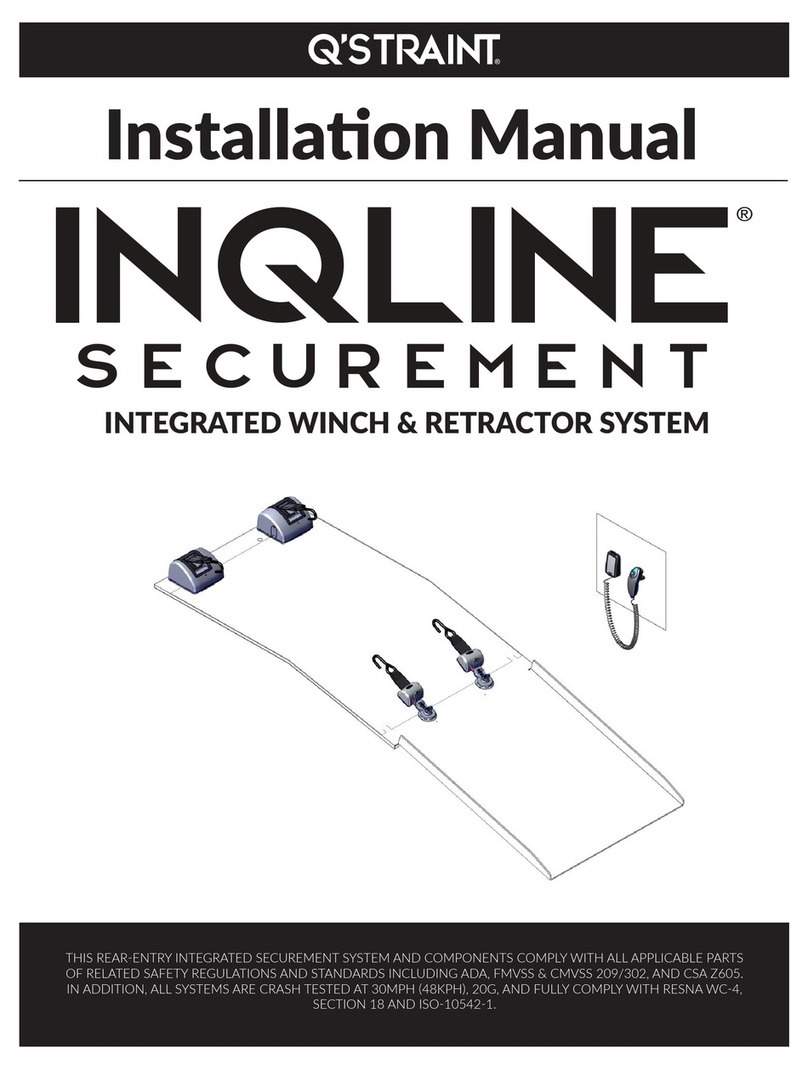
Q'STRAINT INQLINE SECUREMENT User manual

Q'STRAINT
Q'STRAINT QRT-1 Series User manual

Q'STRAINT
Q'STRAINT QLK-150 User manual

Q'STRAINT
Q'STRAINT QLK-150 User manual

Q'STRAINT
Q'STRAINT QLK-150 User manual

Q'STRAINT
Q'STRAINT SURE-LOK DOUBLE INERTIA OCCUPANT BELT User manual

Q'STRAINT
Q'STRAINT ONE User manual

Q'STRAINT
Q'STRAINT QRT-1 Series User manual

Q'STRAINT
Q'STRAINT INQLINE User manual