1 2
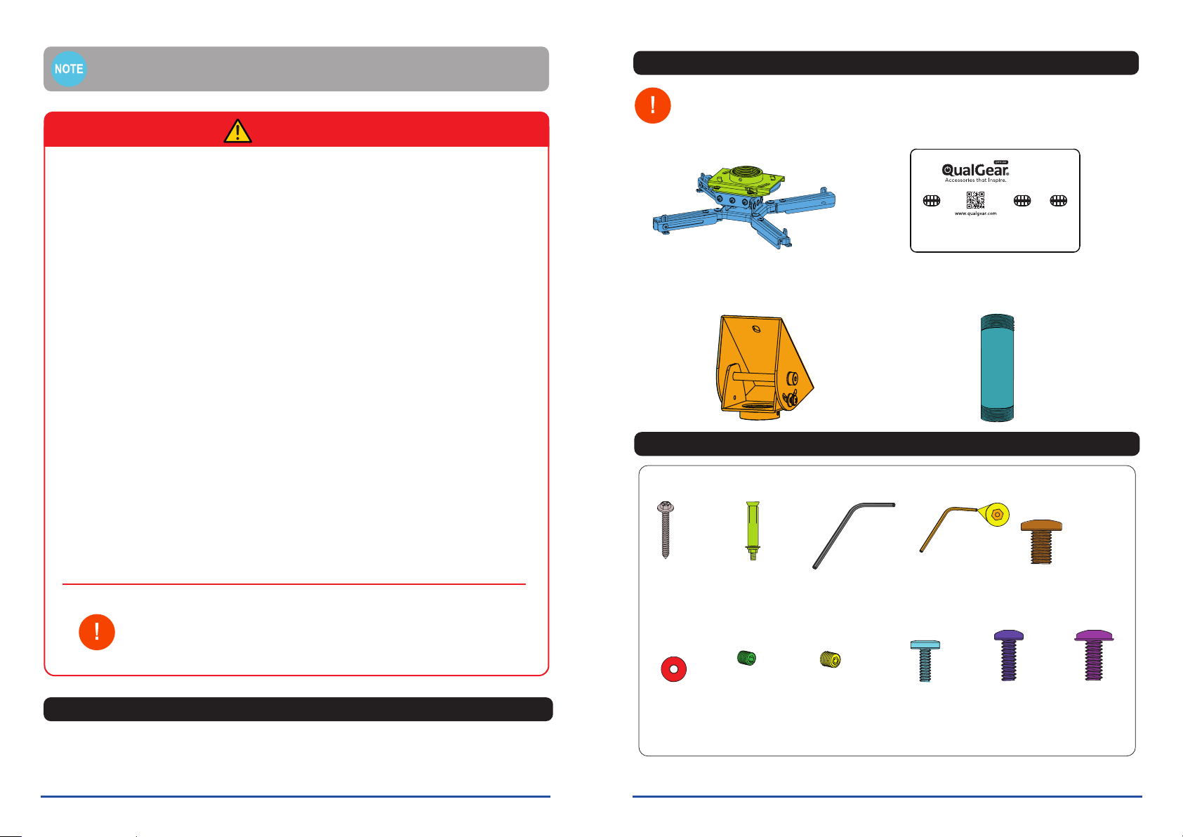
Parts Checklist
IMPORTANT: Before starting the installation, please check to see that product package
includes all parts as shown If any parts are missing or damaged, contact your local
and installation until you receive all the parts.
Hardware Package
M5 x 4mm
Security Screws
M (x4)
M5 x 4mm
Screws
L (x2)
M3 x 8mm
Screws
O (x4)
M4 x 10mm
Screws
P (x4)
M5 x 10mm
Screws
Q (x4)
M 2.5 Allen Key
I (x1)
Screws
F (x3)
Metal Expansion
Anchors
G (x3)
M6 x 10mm
Screws
J (x4)
M4-M6
Allen Key
H (x1)
Please read the entire installation manual before you start installation and assembly.
IMPORTANT:
Installers must verify that the supporting surface safely
supports the combined weight of the equipment and all attached hardware
and components.
Do not begin to install your QualGear
product until you have read and understood
all the instructions and warnings contained
in this installation manual. If you have
any questions regarding the instructions,
for US customers, please contact
QualGear customer support via email at
support@qualgear.com. For all international
customers, please contact your local
distributor.
This product requires installation by
someone who has experience with basic
building construction and fully understands
these instructions.
This product was designed to be installed
and operated exactly as specified in this
manual. Improper installation of this product
may cause damage or serious injury.
QualGear is not liable for the improper use
or installation of its products.
Make sure that the supporting surface
safely supports the combined load of the
equipment and all attached hardware and
components.
Always use an assistant or mechanical
lifting equipment to lift and position the
equipment safely.
Tighten screws firmly, but do not over
tighten. Over tightening can damage the
items, greatly reducing their holding power.
ALL QUALGEAR products are intended
for indoor use only and any outdoor use voids
the limited warranty. For warranty information,
please visit:
http://www.qualgear.com/warranty.php
Never exceed the maximum rated weight
specified in this manual.
All hardware must be used at the
designated points in the installation
instructions to prevent property damage and
personal injury.
This product was designed to be
compatible with all standard 1.5" NPT
pipes.
WARNING
Maintenance
Please check that the ceiling projector mount is secure and safe to use at regular intervals. If you
have any questions regarding any of the instructions or warnings, please contact your local distributor
(OR) contact QualGear technical support via email at support@qualgear.com.
Washers
K (x4)
Projector Mount
A (x1)
3-Inch NPT
Pipe D (x1)
QG-PRO-PM-VCA-B or
QG-PRO-PM-VCA-W
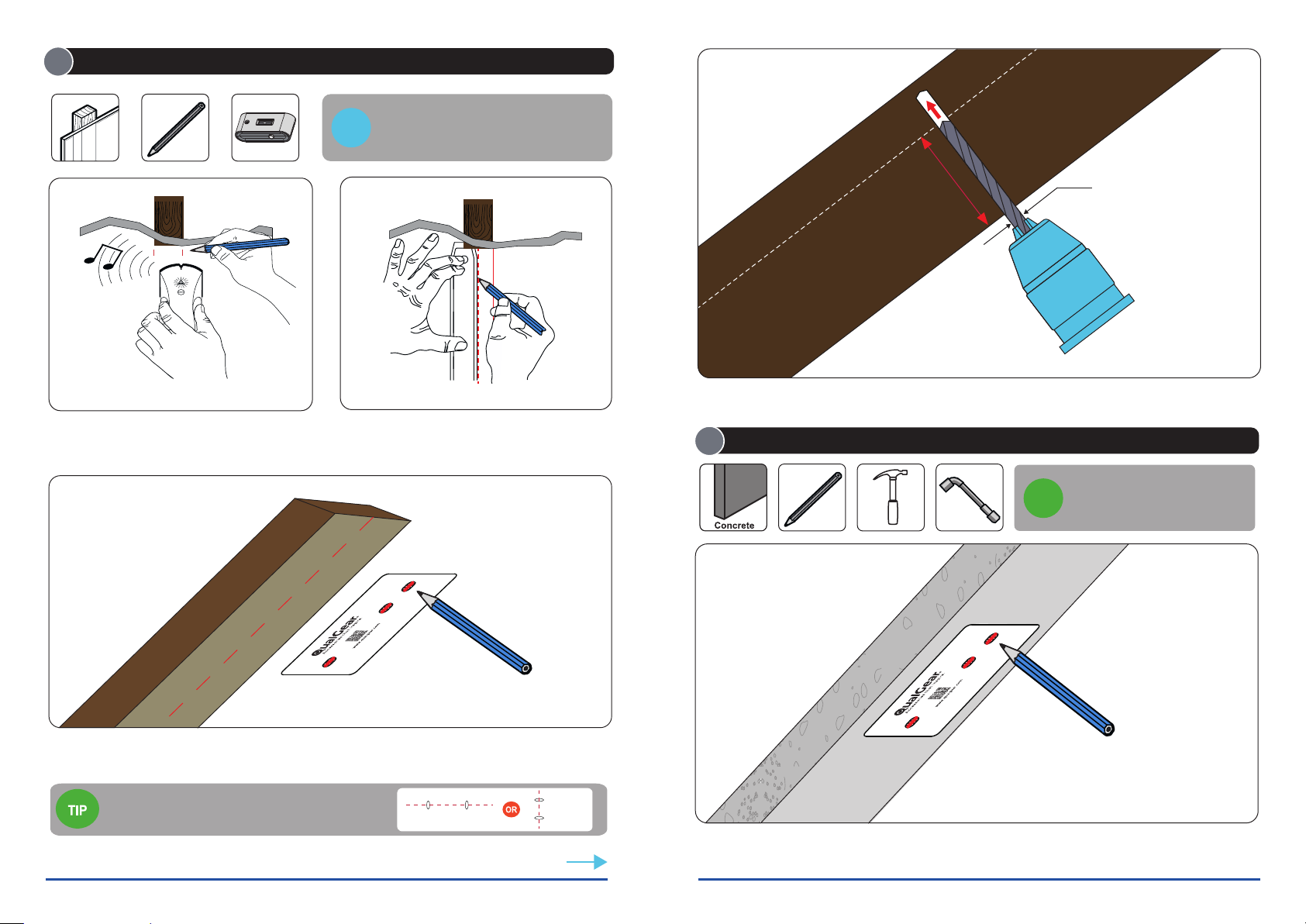
WALL MARKING TEMPLATE
Wall Marking Template
B (x1)
Vaulted Ceiling
Adapter C (x1)
Security