Quick BTQ140 User manual

REV 006
b
High
Quality
Nautical
Equipment
BOW THRUSTER
BTQ140
BTQ185
SINGLE AND DOUBLE
PROPELLER
Manuale d'uso
ELICHE DI MANOVRA DI PRUA
User's Manual
BOW THRUSTERS
IT
EN


3
BOW THRUSTER BTQ140 - BTQ185 IT EN - REV006B
3
Pag. 4
CARATTERISTICHE
Pag. 5
INSTALLAZIONE
- requisiti per l’installazione - il tunnel
Pag. 6
INSTALLAZIONE
- requisiti per l’installazione - il tunnel
Pag. 7
INSTALLAZIONE
- il thruster
Pag. 8
INSTALLAZIONE
- il piede e la flangia di supporto motore
Pag. 9
INSTALLAZIONE
- montaggio dell’elica
Pag. 10
SCHEMA DI COLLEGAMENTO
Pag. 11
AVVERTENZE IMPORTANTI - USO
Pag. 12/13
MANUTENZIONE
Pag. 14/15
RICAMBI
INDICE
Pag. 16
CHARACTERISTICS
Pag. 17
INSTALLATION
- installation requirements - the tunnel
Pag. 18
INSTALLATION
- installation requirements - the tunnel
Pag. 19
INSTALLATION
- the thruster
Pag. 20
INSTALLATION
- gearleg and motor support flange
Pag. 21
INSTALLATION
- propeller fitting
Pag. 22
CONNECTION DIAGRAM
Pag. 23
WARNING - USAGE
Pag. 24/25
MAINTENANCE
Pag. 26/27
SPARE PARTS
INDEX
IT
EN

4
CARATTERISTICHE
IT
BOW THRUSTER BTQ140 - BTQ185 IT EN - REV006B
PRIMA DI UTILIZZARE IL BOW THRUSTER LEGGERE ATTENTAMENTE IL PRESENTE MANUALE D'USO.
IN CASO DI DUBBI CONSULTARE IL RIVENDITORE QUICK
®
ATTENZIONE:
i Bow Thruster Quick®sono stati progettati e realizzati per asservire all’uso nautico.
Non utilizzare questi apparecchi per altri tipi di applicazioni.
Quick®non si assume alcuna responsabilità per i danni diretti o indiretti causati da un uso improprio dell’apparecchio o da
una scorretta installazione.
Il Bow thruster non è progettato per mantenere carichi generati in particolari condizioni atmosferiche (burrasca).
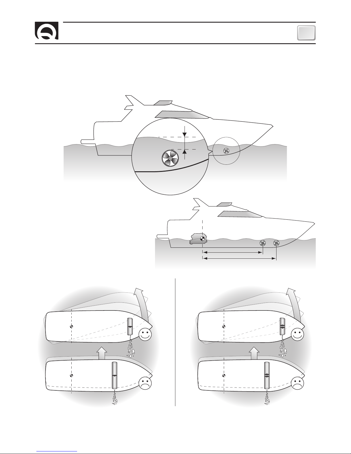
Si raccomanda di affidare a un professionista la predisposizione e il posizionamento del tubo allo scafo. Queste istruzioni
sono generiche, e non illustrano in alcun modo i dettagli delle operazioni di predisposizione del tunnel quale competenza del
cantiere. In caso di eventuali problemi provocati da un’installazione difettosa del tunnel, ne risponderà in pieno l’installatore.
Non installare il motore elettrico nelle vicinanze di oggetti facilmente infiammabili.
LA CONFEZIONE CONTIENE:
bow thruster - dima di foratura - o-ring (per l'assemblaggio) - manuale di istruzioni - condizioni di garanzia.
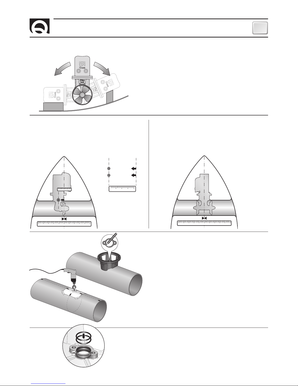
ATTREZZI NECESSARI PER L'INSTALLAZIONE:
BTQ140,
trapano con punta da Ø 6 mm (1/4"); a tazza Ø 27 mm (1"1/16); chiavi maschio esagonale: 4 mm, 5 mm, 6 mm;
chiave a forchetta o poligonale: 17 mm.
BTQ185,
trapano con punta da Ø 9 mm (3/8"); a tazza Ø 32 mm (1"1/4); chiavi maschio esagonale: 5 mm, 6 mm, 8 mm;
chiave a forchetta o poligonale: 19 mm.
ACCESSORI QUICK
®
CONSIGLIATI:
TCD1022 - TCD1042 - TCD1044 - TCD1062 - TMS - TSC - PSS - TFH3 - TFH6
MODELLI BTQ1403012 BTQ1404012
N° Eliche 1
Tunnel Ø 140 mm (5” 33/64)
Potenza Motore 1,5 KW 2,2 KW
Tensione 12 V 12 V
Sezione cavi 50 mm2(AWG 1) 95 mm2(AWG 3/0)
Fusibile 150A CNL DIN 225A CNL DIN
Spinta 30 kgf (66.1 lb) 40 kgf (88.2 lb)
Peso 11,8 kg (26.0 lb) 12,4 kg (27.3 lb)
Spessori limite dei tubi: min. 4,5 mm - max 6,5 mm (min. 11/64” - max 1/4”)
MODELLI BTQ1805512 BTQ1805524 BTQ1807512 BTQ1807524 BTQ1809512 BTQ1809524
N° Eliche 1
Tunnel Ø 185 mm (7” 18/64)
Potenza Motore 3,0 KW 4,0 KW 6,0 KW
Tensione 12 V 24 V 12 V 24 V 12 V 24 V
Sezione cavi 120 mm2
(AWG 4/0)
70 mm2
(AWG 2/0)
150 mm2
(AWG 300MCM)
120 mm2
(AWG 4/0)
2 x 95 mm2
(2 x AWG 3/0)
120 mm2
(AWG 4/0)
Fusibile 250A CNL DIN 150A CNL DIN 350A CNL DIN 250A CNL DIN 350A CNL DIN 250A CNL DIN
Spinta 55 kgf (121.2 lb) 75 kgf (165.3 lb) 95 kgf (209.5 lb)
Peso 17,2 kg (37.9 lb) 17,5 kg (38.6 lb) 17,5 kg (38.6 lb) 20,5 kg (45.2 lb) 27,2 kg (59.9 lb) 24,4 kg (53.8 lb)
Spessori limite dei tubi: min. 4,5 mm - max 6,5 mm (min. 11/64” - max 1/4”)
MODELLI BTQ1806512 BTQ1806524 BTQ1808512 BTQ1808524 BTQ1810512 BTQ1810524
N° Eliche 2 controrotanti
Tunnel Ø 185 mm (7” 18/64)
Potenza Motore 3,3 KW 4,3 KW 6,3 KW
Tensione 12 V 24 V 12 V 24 V 12 V 24 V
Sezione cavi 120 mm2
(AWG 4/0)
70 mm2
(AWG 2/0)
150 mm2
(AWG 300MCM)
120 mm2
(AWG 4/0)
2 x 95 mm2
(2 x AWG 3/0)
120 mm2
(AWG 4/0)
Fusibile 275A CNL DIN 175A CNL DIN 400A CNL DIN 275A CNL DIN 400A CNL DIN 275A CNL DIN
Spinta 65 kgf (143.3 lb) 85 kgf (187.4 lb) 105 kgf (231.5 lb)
Peso 18 kg (39.7 lb) 18,3 kg (40.3 lb) 18,3 kg (40.3 lb) 21,3 kg (47.0 lb) 28 kg (61.7 lb) 25,2 kg (55.5 lb)
Spessori limite dei tubi: min. 4,5 mm - max 6,5 mm (min. 11/64” - max 1/4”)
Quick®si riserva il diritto di apportare modifiche alle caratteristiche tecniche dell'apparecchio e al contenuto di questo manuale senza alcun preavviso.
In caso di discordanze o eventuali errori tra il testo tradotto e quello originario in italiano, fare riferimento al testo italiano o inglese.
F

5
INSTALLAZIONE
IT
BOW THRUSTER BTQ140 - BTQ185 IT EN - REV006B
minimo 0,75 volte
Ø tunnel
BARICENTRO
L 1
L 2
A B
REQUISITI PER L'INSTALLAZIONE
IL TUNNEL
• La posizione del tunnel dipenderà dalla forma interna ed esterna della prua della imbarcazione.
• La sistemazione ottimale del tunnel, sarà più a prua e più a fondo possibile, minimo 0,75 volte il diametro del tunnel dalla linea
di galleggiamento.
• Per evitare fenomeni di cavitazione nell’elica, si
dovrà posizionare il tunnel più a fondo possibile.
• L’effetto di leva nell’imbarcazione è proporzionale
all’aumento della distanza (L1 e L2) che si rileva, tra
il baricentro e la posizione del tunnel A e B.
• L’aumento della lunghezza del tunnel aumenta l’effetto delle perdite di carico diminuendo la forza nominale di propulsione.
• Per limitare le perdite di carico, la lunghezza consigliata è pari a 3-4 volte il diametro del tubo; è tollerato un rapporto fino a 6
volte il diametro.
F
Per avere maggiore effetto leva preferire la
posizione B alla posizione A.
ELICA SINGOLA ELICA DOPPIA

6
IT
BOW THRUSTER BTQ140 - BTQ185 IT EN - REV006B
INSTALLAZIONE
• Le estremità arrotondate del tunnel limitano l’innesco di turbolenze e cavitazione, migliorando le prestazione della spinta
dell’elica e riducendo al minimo la rumorosità.
• Quando l’imbarcazione è in movimento, la forza prodotta dal flusso dell’acqua produce della resistenza sulla faccia po-
steriore del tunnel, che diventa un’area piatta al flusso dell’acqua. Per limitare questo fenomeno, prevedere una rientranza
nella parte posteriore del tunnel. Questa dipenderà dalla sagoma dello scafo dell’imbarcazione, o in alternativa, realizzare un
deflettore nella parte anteriore del tunnel.
• Nel caso in cui il tunnel sia vicino alla linea di galleggiamento è consigliabile prevedere l’inserimento di
una grata all’estremità del tubo.
La grata deve avere maglie verticali e più larghe possibili, per non contrastare la spinta dell’elica.
Le maglie verticali impediscono l’ingresso della maggior parte degli oggetti galleggianti.
ELICA SINGOLA
ELICA DOPPIA

7
INSTALLAZIONE
IT
BOW THRUSTER BTQ140 - BTQ185 IT EN - REV006B
IL THRUSTER
• Per posizionare il thruster nel tubo trovare la mezzeria del
tubo e spostarsi del valore dato (
a destra o a sinistra vedi
NOTA a pag.12
) nello schema sottostante affinchè l’elica si
posizioni nell’esatta metà della lunghezza interna del tunnel.
• Utilizzare la flangia per contrassegnare sul tubo il centro
dei fori.
• Fissare la dima di foratura sui riferimenti accertandosi che
siano allineati con precisione alla mezzeria del tubo.
N.B. Tutti i fori devono essere allineati con precisione alla
mezzeria del tunnel, in quanto la tolleranza tra l’elica ed i
tunnel è minima.
• Fare attenzione che non vi siano residui di resina nella
parte di contatto fra la flangia e il tubo; ciò potrebbe causare
disallineamenti. E’ necessario asportare con carta vetrata
eventuali residui di resina e di tutti gli eventuali impedimenti
al corretto contatto.
• Il thruster può essere installato con qualunque angolo
all’interno di 90º dalla verticale.
• Se il motore elettrico è posizionato per necessità con un
angolo superiore a 30º rispetto alla verticale, si rende neces-
sario la realizzazione in opera di un apposito sostegno.
10 2 3 4 5 6 7 8 9 10
10 2 3 4
10 2 3 4
BTQ14 60 mm
BTQ18 80 mm
• Inserire due o-ring nelle specifiche sedi all’interno della
flangia.
10 2 3 4 5 6 7 8 9 10
• Per posizionare il thruster nel tubo trovare la mezzeria del
tubo affinchè la flangia si posizioni nell’esatta metà della lun-
ghezza interna del tunnel.
ELICA SINGOLA ELICA DOPPIA

8
IT
BOW THRUSTER BTQ140 - BTQ185 IT EN - REV006B
INSTALLAZIONE
SILICONE
IL PIEDE RIDUTTORE E LA FLANGIA DI SUPPORTO MOTORE
SILICONE
• Ingrassare la parte terminale dell’albero del piede riduttore;
montare la chiavetta nella propria sede.
• Inserire il giunto elastico nella parte terminale dell’albero
del piede riduttore.
• Inserire il motore sul giunto elastico, fissare con le 4 viti e
rondelle in dotazione.
• Ingrassare la parte terminale dell’albero motore; montare la
chiavetta nella propria sede.
• Procedere al montaggio del piede riduttore con la specifica guarnizione di tenuta.
• Come ulteriore precauzione contro l’ingresso d’acqua, applicare silicone per uso nautico nella zona di contatto tra flangia e
tubo.
• Fissare il tutto con la flangia utilizzando le specifiche viti e rondelle.
ELICA SINGOLA ELICA DOPPIA

9
INSTALLAZIONE
IT
BOW THRUSTER BTQ140 - BTQ185 IT EN - REV006B
L’ELICA
PANNELLO DI COMANDO
Per l’installazione del pannello di comando, fare riferimento ai manuali d’uso “TCD 1022 - TCD 1042 - TCD 1044”.
LOCTITE
ATTENZIONE:
accertarsi, ad assemblaggio ultimato,
che l’elica sia ben centrata all’interno del tunnel.
MONTAGGIO DELL’ELICA
Inserire la spina di trascinamento
A
nel foro sull’albero del piede riduttore
B
, assemblare l’elica C al riduttore ingranandola alla
spina di trascinamento
A
, fissare l’elica con il dado autofrenante
D
. L’anodo
E
va bloccato con la vite
F
bagnata con adesivo
strutturale (tipo loctite).
A
B
CD
EF
MONTAGGIO DELLE ELICHE
Inserire le chiavette di trascinamento
A
sul piede riduttore
B
; assemblare le eliche
C
e
D
al piede del riduttore ingranandole alle
spine di trascinamento
A
e fissare le eliche con i dadi autofrenanti
E
.
Gli anodi
F
si inseriscono sul dado
E
e vengono fissati con le viti
G
bagnate con adesivo (tipo loctite) frena-filetti.
LOCTITE
A
B
C
E
G
F
A
D
E
F
G

10
IT
BOW THRUSTER BTQ140 - BTQ185 IT EN - REV006B
SCHEMA DI COLLEGAMENTO
M1
A A
S S
SX
+
-
DX
-
M2
SISTEMA BASE
BTQ14 - BTQ18
MOTORE
BATTERIA
12/24V
STACCABATTERIA
NERO
FUSIBILE
RAPIDO 4A
FUSIBILE
VEDI TABELLA
A PAG.4
INTERRUTTORE
ROSSO
NERO
ROSSO
ALLA BATTERIA
SERVIZI
SDOPPIATORE
(OPZIONALE)
PROLUNGHE
(OPZIONALI)
*
*
TCD 1042 TCD 1022
*
NEGATIVO DEI GRUPPI BATTERIA IN COMUNE.
*
*
ATTENZIONE: IN CASO DI SOVRATEMPERATURA LA PROTEZIONE TERMICA SUL MOTORE SI APRIRÀ E INTERROMPERÀ IL CONTATTO NEGATIVO SUL
TELERUTTORE. ATTENDERE IL TEMPO NECESSARIO ALLA RIATTIVAZIONE.
*PROTEZIONE
TERMICA
PANNELLI DI COMANDO
ACCESSORI QUICK
®
PER L’AZIONAMENTO
DELL’ELICA DI MANOVRA
STERN
BOW
COMANDO
INTERRUTTURE
DI LINEA TSC
INTERRUTTORE
BATTERIE
PARALLELO- SERIE PSS
PORTAFUSIBILI TFH3 - TFH6
INTERRUTTORE
DI LINEA TMS
TCD 1022 TCD 1042 TCD 1044 TCD 1062

11
IT
BOW THRUSTER BTQ140 - BTQ185 IT EN - REV006B
AVVERTENZE - USO
AVVERTENZE IMPORTANTI
ATTENZIONE:
questo bow thruster non è realizzato per un funzionamento continuo.
E’ provvisto di protezioni che ne limitano il funzionamento fino ad un tempo massimo, come riportato sul manuale dei
comandi. E’ assolutamente vietato bypassare, o modificare tali protezioni per aumentare il tempo di funzionamento, pena
la decadenza della garanzia e di qualsiasi responsabilità da parte di Quick SPA.
ATTENZIONE:
accertarsi che non vi siano bagnanti ed oggetti galleggianti nelle vicinanze, prima d’avviare il thruster.
ATTENZIONE:
non deve essere presente materiale infiammabile nel gavone o nella zona in cui sia presente il motore del
bow thruster.
ATTENZIONE:
non utilizzare il bow thruster fuori dall’acqua per un tempo superiore a 10 secondi.
ATTENZIONE:
durante l’ormeggio, si raccomanda di non lasciare cime libere in acqua che potrebbero essere risucchiate
dalle eliche causandone la rottura.
USO DELL’ELICA DI MANOVRA
ACCENSIONE
L’accensione avviene in conseguenza all’attivazione di un pannello TCD.
Per l’uso dell’elica retrattile fare riferimento al manuale del comando TCD.
Se fosse necessario installare il bow thruster nella posizione opposta, bisognerà invertire il collegamento dei due cavi (blu e gri-
gio) del cavo comando sul teleinvertitore.
ELICA SINGOLA ELICA DOPPIA
NOTA:
il bow thruster va installato con l’elica a destra del
piede riduttore (vedi figura).
NOTA:
il bow thruster va installato con l’elica
RH
a destra del
piede riduttore (vedi figura).
RHRH

12
IT
BOW THRUSTER BTQ140 - BTQ185 IT EN - REV006B
1
2
3
45
6
10
9
12
13
15 16 17
19
30
29
20
25 24
21
27
26
18
9
11
12
14
28
23
22
23
22
7
8
13
15
16 17
17 16
15
MANUTENZIONE
BTQ ELICA SINGOLA E DOPPIA

13
IT
BOW THRUSTER BTQ140 - BTQ185 IT EN - REV006B
POS. DENOMINAZIONE
1 Vite fissaggio motore
2 Rondella fissaggio motore
3 Motore
4 Parastrappi
5 Semigiunto
6 Flangia motore
7 Guarnizione riduttore
8 O-Ring
9 Chiavetta
10 Piede riduttore elica singola
11 Piede riduttore elica doppia
12 Spina trascinamento elica
13 Elica destra (RH)
14 Elica sinistra (LH)
15 Dado fissaggio elica
16 Puntale anodico
17 Vite fissaggio puntale anodico
18 Rondella
19 Vite fissaggio riduttore
20 Cassetta teleinvertitori
21 Staffa cassetta teleinvertitori
22 Rondella
23 Vite
24 Grower
25 Vite fissaggio cassetta teleinvertitori
26 Protezione termica BTQ + cavo
27 Cavo comando
28 Distanziale carter B
29 Carter cassetta teleinvertitori
30 Fissaggio carter cassetta teleinvertitori
MANUTENZIONE
I Thruster Quick®sono costituiti da materiale resistenti all’ambiente
marino: è indispensabile, in ogni caso, rimuovere periodicamente
i depositi di sale che si formano sulle superfici esterne per evitare
corrosioni e di conseguenza inefficienza del sistema.
ATTENZIONE:
accertarsi che non sia presente l’alimenta-
zione al motore elettrico quando si eseguono le operazioni
di manutenzione.
Smontare una volta all’anno, seguendo i seguenti punti:
• Pulire eliche (13 e 14), tunnel e piede riduttore (10 o 11).
• Sostituire gli anodi di zinco (effettuare più frequentemente se
necessario).
• Sostituire le eliche se danneggiate o usurate.
• Controllare il serraggio di tutte le viti.
• Accertarsi che non vi siano infiltrazioni di acqua all’interno.
• Verificare che tutte le connessioni elettriche siano ben fissate e
prive di ossido.
• Verificare che le batterie siano in buone condizioni.
ATTENZIONE:
non verniciare gli anodi di zinco (16), le sigil-
lature e gli alberi dei piedi riduttori dove alloggiano le eliche.

14
IT
BOW THRUSTER BTQ140 - BTQ185 IT EN - REV006B
RICAMBI
OSP KIT CASSETTA TELEINV 150A 12V FVSGRCT15012A00
OSP KIT CASSETTA TELEINV 150A 24V FVSGRCT15024A00
OSP KIT CASSETTA TELEINV 350A 12V FVSGRCT35012A00
OSP KIT CASSETTA TELEINV 350A 24V FVSGRCT35024A00
OSP KIT CARTER ‘A’ BTQ FVSGCARTABTQA00
OSP KIT CARTER ‘B’ BTQ FVSGCARTABTQB00
OSP KIT GIUNTO BTQ 140 30/40KG S FVSGG141114SA00
OSP KIT GIUNTO BTQ 185 FVSGG1851414A00
OSP MOTOR 1500W 12V BTQ125-140+T FVEMFEL15121400
OSP MOTOR 2200W 12V BTQ125-140+T FVEMFEL22121400
OSP MOTOR 3000W 12V BTQ185+T FVEMFEL30121800
OSP MOTOR 3000W 24V BTQ185+T FVEMFEL30241800
OSP MOTOR 3300W 12V BTQ185+T FVEMFEL33121800
OSP MOTOR 3300W 24V BTQ185+T FVEMFEL33241800
OSP MOTOR 4000W 12V BTQ185+T FVEMFEL40121800
OSP MOTOR 4000W 24V BTQ185+T FVEMFEL40241800
OSP MOTOR 4300W 12V BTQ185+T FVEMFEL43121800
OSP MOTOR 4300W 24V BTQ185+T FVEMFEL43241800
OSP MOTOR 6000W 12V BTQ185+T FVEMFEL60121800
OSP MOTOR 6000W 24V BTQ185+T FVEMFEL60241800
OSP MOTOR 6300W 12V BTQ185+T FVEMFEL63121800
OSP MOTOR 6300W 24V BTQ185+T FVEMFEL63241800

15
IT
BOW THRUSTER BTQ140 - BTQ185 IT EN - REV006B
RICAMBI
OSP KIT FLANGIA PER ELICA BTQ140 FVSGFLBTQ140A00
OSP KIT FLANGIA PER ELICA BTQ185 FVSGFLBTQ185A00
OSP KIT RIDUTTORE BTQ140 FVSGGBBT1400A00
OSP KIT RIDUTTORE BTQ185 FVSGGBBT1850A00
OSP KIT RIDUTTORE BTQ185 DP FVSGGBBT1850A00
OSP KIT ELICA D140 R FVSGEL140R00A00
OSP KIT ELICA D185 RH FVSGEL185R00A00
OSP KIT ELICA D185 LH FVSGEL185L00A00
OSP KIT ANODO PER ELICA BTQ140 FVSGANBTQ140A00
OSP KIT ANODI PER ELICHE BTQ185 FVSGANBTQ185A00

16
CHARACTERISTICS
EN
BOW THRUSTER BTQ140 - BTQ185 IT EN - REV006B
BEFORE USING THE BOW THRUSTER, READ THIS INSTRUCTION MANUAL CAREFULLY.
IF IN DOUBT, CONTACT YOUR NEAREST QUICK
®
DEALER.
WARNING:
Quick®Bow Thrusters have been designed and constructed only for nautical use.
Do not use these appliances for other uses.
Quick®shall accept no responsibility for direct or indirect damages caused by improper use of the appliance or an improper
installation.
The Bow Thruster is not designed to maintain loads generated in particular atmospheric conditions (storms).
We recommend you entrust preparation and positioning of the tube on the hull to a skilled professional. These are generic
instructions and do not give details of the preparatory operations for installing the tunnel, since this is the competence of the
boatyard. The installer shall bear full responsibility for any problems caused by defective installation of the tunnel.
Do not install the electric motor near easily inflammable objects.
THE PACKAGE CONTAINS:
bow thruster - drill template - o-ring (for assembly) - user’s manual - conditions of warranty.
TOOLS REQUIRED FOR INSTALLATION:
BTQ140,
drill and drill bits Ø 6 mm (1/4"); hollow mill Ø 27 mm (1"1/16); hexagonal male key: 4 mm, 5 mm, 6 mm;
fork or polygonal key: 17 mm.
BTQ185,
drill and drill bits da Ø 9 mm (3/8"); hollow mill Ø 32 mm (1"1/4); hexagonal male key: 5 mm, 6 mm, 8 mm;
fork or polygonal key: 19 mm.
QUICK
®
”ACCESSORIES RECOMMENDED:
TCD1022 - TCD1042 - TCD1044 - TCD1062 - TMS - TSC - PSS - TFH3 - TFH6
MODELS BTQ1403012 BTQ1404012
N° Propellers 1
Tunnel Ø 140 mm (5” 33/64)
Motore Power 1,5 KW 2,2 KW
Voltage 12 V 12 V
Section of wire 50 mm2(AWG 1) 95 mm2(AWG 3/0)
Fuse 150A CNL DIN 225A CNL DIN
Thrust 30 kgf (66.1 lb) 40 kgf (88.2 lb)
Weight 11,8 kg (26.0 lb) 12,4 kg (27.3 lb)
Limit thickness values of the tubes: min. 4,5 mm - max 6,5 mm (min. 11/64” - max 1/4”)
MODELS BTQ1805512 BTQ1805524 BTQ1807512 BTQ1807524 BTQ1809512 BTQ1809524
N° Propellers 1
Tunnel Ø 185 mm (7” 18/64)
Motore Power 3,0 KW 4,0 KW 6,0 KW
Voltage 12 V 24 V 12 V 24 V 12 V 24 V
Section of wire 120 mm2
(AWG 4/0)
70 mm2
(AWG 2/0)
150 mm2
(AWG 300MCM)
120 mm2
(AWG 4/0)
2 x 95 mm2
(2 x AWG 3/0)
120 mm2
(AWG 4/0)
Fuse 250A CNL DIN 150A CNL DIN 350A CNL DIN 250A CNL DIN 350A CNL DIN 250A CNL DIN
Thrust
55 kgf (121.2 lb) 75 kgf (165.3 lb) 95 kgf (209.5 lb)
Weight 17,2 kg (37.9 lb) 17,5 kg (38.6 lb) 17,5 kg (38.6 lb) 20,5 kg (45.2 lb) 27,2 kg (59.9 lb) 24,4 kg (53.8 lb)
Limit thickness values of the tubes: min. 4,5 mm - max 6,5 mm (min. 11/64” - max 1/4”)
MODELS BTQ1806512 BTQ1806524 BTQ1808512 BTQ1808524 BTQ1810512 BTQ1810524
N° Propellers 2 counter rotating
Tunnel Ø 185 mm (7” 18/64)
Motore Power 3,3 KW 4,3 KW 6,3 KW
Voltage 12 V 24 V 12 V 24 V 12 V 24 V
Section of wire 120 mm2
(AWG 4/0)
70 mm2
(AWG 2/0)
150 mm2
(AWG 300MCM)
120 mm2
(AWG 4/0)
2 x 95 mm2
(2 x AWG 3/0)
120 mm2
(AWG 4/0)
Fuse 275A CNL DIN 175A CNL DIN 400A CNL DIN 275A CNL DIN 400A CNL DIN 275A CNL DIN
Thrust 65 kgf (143.3 lb) 85 kgf (187.4 lb) 105 kgf (231.5 lb)
Weight 18 kg (39.7 lb) 18,3 kg (40.3 lb) 18,3 kg (40.3 lb) 21,3 kg (47.0 lb) 28 kg (61.7 lb) 25,2 kg (55.5 lb)
Limit thickness values of the tubes: min. 4,5 mm - max 6,5 mm (min. 11/64” - max 1/4”)
Quick®reserves the right to introduce changes to the equipment and the contents of this manual without prior notice.
In case of discordance or errors in translation between the translated version and the original text in the Italian language, reference will be made to the Italian or English text.
F

17
INSTALLATION
EN
BOW THRUSTER BTQ140 - BTQ185 IT EN - REV006B
minimum 0,75
times tunnel Ø
BARYCENTRE
L 1
L 2
A B
INSTALLATION REQUISITES
THE TUNNEL
• The position of the tunnel will depend on the interior and exterior shape of the boats bow.
• Optimal positioning of the tunnel will be in the bow and as low as possible, at least 0.75 times the tunnel diameter from the
waterline.
• To avoid cavitation in the propeller, the tunnel
must be positioned as low as possible.
• The lever effect in the boat is proportional to the
increase of the distance (L1 and L2) between the
barycentre and the position of the tunnel A and B.
• An increase in the length of the tunnel increases the effect of the loss of charge, decreasing the nominal driving force.
• To limit losing charge, the optimal length is equal to 3-4 times the tube diameter; a ratio of up to 6 can be tolerated.
F
For greater lever effect prefer position B to
position A.
SINGOL PROPELLER DOUBLE PROPELLER

18
EN
BOW THRUSTER BTQ140 - BTQ185 IT EN - REV006B
INSTALLATION
• The rounded ends of the tunnel limit the creation of turbulences and cavitations, improving performance of the propeller thrust
and reducing noise levels to a minimum.
• The force produced by the flow of the water when the boat is moving produces resistance on the rear face of the tunnel,
which is an area exposed frontally to the water flow.
To limit this phenomenon, prepare an indentation in the rear part of the tunnel. Otherwise, create a deflector on the front
part of the tunnel.
• If the tunnel is near the waterline, it is advisable to fit a grating at the end of the tube.
The grating must have as large a vertical mesh as possible to avoid contrasting the propeller thrust.
The vertical mesh prevents the entry of most of the floating objects.
SINGOL PROPELLER
DOUBLE PROPELLER

19
INSTALLATION
EN
BOW THRUSTER BTQ140 - BTQ185 IT EN - REV006B
IL THRUSTER
To position the thruster in the tube, find the half-way point
and move to the value shown (
to the right or to the left see
NOTE page 23
)in the table below so that the propeller is
positioned exactly half way along the internal length of the
tunnel.
• Use the flange to mark the centre of the holes on the tube.
• Fix the drilling template on the reference points, making
sure they are aligned with precision at the half-way point of
the tube.
N.B. All holes must be exactly aligned with the half-way point
of the tunnel, since tolerance between propeller and tunnel
is minimal.
• Take care that there are no resin residues in the contact
area between flange and tube; this could cause misalign-
ment. Any resin residues and any other hindrance to correct
contact must be removed by sandpaper.
• The thruster can be installed at any angle within 90° from
vertical.
• If the electric motor is positioned of necessity at an angle
of more than 30° from vertical, a special support must be
constructed.
10 2 3 4 5 6 7 8 9 10
10 2 3 4
10 2 3 4
BTQ14 60 mm
BTQ18 80 mm
• Insert two o-rings into the special seats inside the flange.
10 2 3 4 5 6 7 8 9 10
• To position the thruster in the tube, find the half-way point.
SINGOL PROPELLER DOUBLE PROPELLER

20
EN
BOW THRUSTER BTQ140 - BTQ185 IT EN - REV006B
INSTALLATION
SILICONE
GEARLEG AND MOTOR SUPPORT FLANGE
SILICONE
• Grease the terminal part of the gearleg shaft; fit the small
key into its seat.
• Insert the elastic joint in the terminal part of the gearleg
shaft.
• Insert the motor onto the elastic joint; fasten it with the 4
screws and washers provided.
• Grease the terminal part of the gearleg shaft; fit the small
key into its seat.
• Proceed with fitting the gearleg with the special seal gasket.
• For further protection against the entry of water, apply silicone for nautical use around the point of contact between flange and
tube.
• Fasten everything to the flange using the special screws and washers.
SINGOL PROPELLER DOUBLE PROPELLER
This manual suits for next models
1
Table of contents
Languages:
Other Quick Outboard Motor manuals

Quick
Quick BTR1806512 User manual

Quick
Quick BTQ250 Series User manual

Quick
Quick BTR250 User manual

Quick
Quick BTQ1403012 User manual

Quick
Quick BTR140 Series Guide

Quick
Quick BTQ125 series Guide

Quick
Quick BTR185 User manual

Quick
Quick BT386HY455 User manual

Quick
Quick BT185HY080 User manual

Quick
Quick BTR Series User manual

Quick
Quick BTQR1806512 User manual

Quick
Quick BTAC Series User manual

Quick
Quick BT386AC420 User manual

Quick
Quick BTQ110 series User manual

Quick
Quick BTR185 Guide

Quick
Quick BTH 386 C00 Guide

Quick
Quick BTH 513 Guide

Quick
Quick BTQ300 Series User manual

Quick
Quick BTQ Series Guide

Quick
Quick BTAC Series User manual