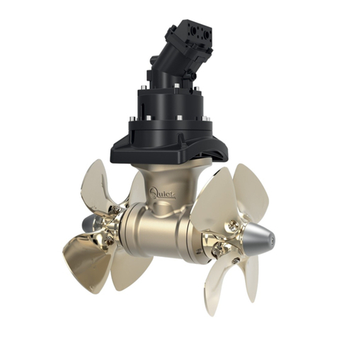
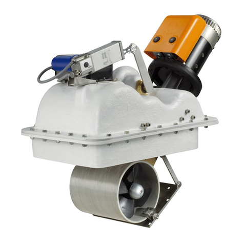
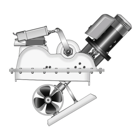
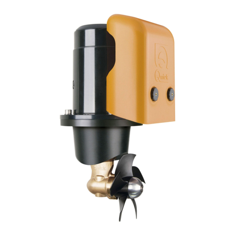
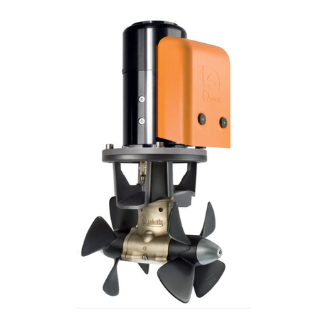
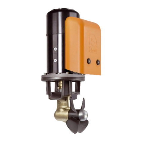
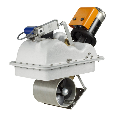
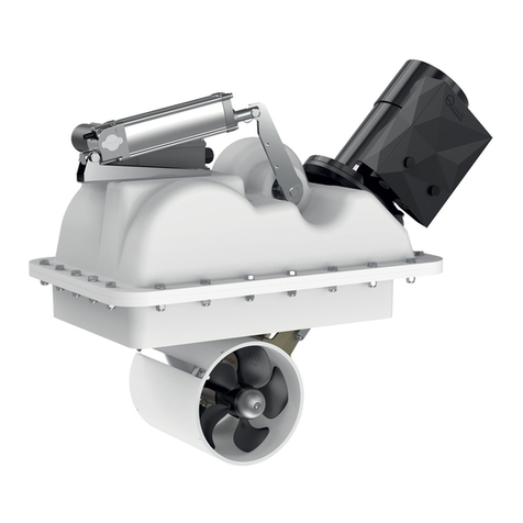
Quick BTR Series User manual

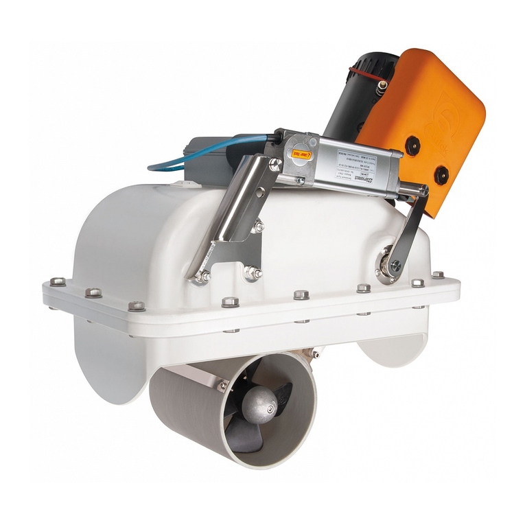
BTR Series
BTR 140 30 - 140 40
BTR 185 65 - 185 85 - 185 105
BTR 250 120 - 250 140 - 250 240
BTR 300 250 - 300 270 - 300 300
RETRACTABLE THRUSTERS
*EN - INSTALLATION AND USER'S MANUAL *Other languages available by scanning the QR code on the
back of this manual or on the label on the product.
IT
*Altre lingue disponibili scansionando il codice QR presente
sul retro del seguente manuale o sull’etichetta alloggiata sul
prodotto.
ES *Otros idiomas disponibles escaneando el código QR en la
parte posterior de este manual o en la etiqueta del producto.
FR *Autres langues disponibles en scannant le code QR au dos
de ce manuel ou sur l'étiquette du produit.
DE
*Andere Sprachen sind durch Scannen des QR-Codes auf der
Rückseite dieser Betriebsanleitung oder auf dem Aufkleber
am Produkt verfügbar.
PT *Outros idiomas disponíveis, digitalizando o código QR no
verso deste manual ou no rótulo do produto.
REV 001C
January, 2023


BTR Series EN
INDEX
QUICK BTR SERIES INSTALLATION AND USER’S MANUAL - REV 001C
1 - Information about the product 5
1.0 - Technical Data 5
2 - Supply and equipment 6
2.0 - Standard supply and material included in the package 6
2.1 - Tools required for installation 6
2.2 - Recommended Quick®accessories not included 6
3 - Introduction 6
3.0 - Important notes 6
3.1 - Precautions 7
3.2 - Precautions for the installer 7
3.3 - Installation requirements 7
4 - Installation 8
4.0 - Thrusters position 8
4.1 - Counter flange installation 9
4.2 - Construction and installation of the closing hatch 11
4.3 - Retractable thruster installation 13
4.4 - Motor installation 14
4.5 - Check and mechanical adjustment of the system 14
4.6 - Installing the cable in the hatch 14
4.7 - Adjustment procedure 15
4.8 - Actuator adjustment 16
4.9 - Installing spring end-of-stroke cables 16
5 - Wiring diagram 17
5.0 - BTR basic system 17
5.1 - RTC R1 board 18
6 - Operation 19
6.0 - Dip-Switch for option selection 19
6.1 - Actuator current rotary selector 19
7 - Signalling 20
7.0 - Light signals 20
8 - Important warnings 21
8.0 - Important cautions 21
9 - Use 21
9.0 - Retractable thruster use 21
9.1 - Manual closing of the thruster in case of emergency 22
10 - Maintenance 22
11 - Product disposal 22
12 - List of components 23
12.0 - BTR 140 24
12.1 - BTR 185 25
12.2 - BTR 250 26
12.3 - BTR 300 27
13 - Spare parts 28
14 - Dimensions 29


BTR Series EN
QUICK BTR Series INSTALLATION AND USER’S MANUAL - REV 001C
5
1.0 - Technical Data
MODELS BTR 140-30 BTR 140-40
NO. Of Propellers Single
Tunnel Ø 140mm (5” 33/64)
Motor power 1.5 kW 2.2 kW
Voltage 12 V 12 V
Fuse 150A CNL DIN 225A CNL DIN
Thrust 30 kgf (66 lb) 40 Kgf (88.2 lb)
Weight 26.4 kg (58.2 lb) 27.3 kg (60.2 lb)
L<5m 35mm² (AWG 2) 50mm² (AWG 1)
5.1 < L < 10m
50mm² (AWG 1) 70mm² (AWG 2/0)
10.1 < L <
20m
70mm² (AWG 2/0) 95mm² (AWG 3/0)
MODELS BTR 185-65 BTR 185-85 BTR 185-105
NO. Of Propellers 2 counter rotating (technopolymer)
Tunnel Ø 185mm (7” 9/32) in
Motor power 3.3 kW 4.3 kW
Voltage 12 V 24 V 12 V 24 V 12 V 24 V
Fuse 275 A CNL DIN 175 A CNL DIN 400 A CNL DIN 275 A CNL DIN 400 A CNL DIN 275 A CNL DIN
Thrust 65 kgf (143.3 lb) 85 kgf (187.4 lb) 105 kgf (231.5 lb)
Weight 37.6 kg (82.9 lb) 37.8 kg (83.3 lb) 37.9 kg (83.5 lb) 40.5 Kg (89.3 lb) 46.4 kg (102.3 lb) 44 kg (97.0 lb)
L<5m 70mm2
(AWG 2/0)
50mm2
(AWG 1)
2 x 50mm2
(2 x AWG 1)
70 mm2
(AWG 2/0)
2 x 70mm2
(2 x AWG 2/0)
70mm2
(AWG 2/0)
5.1 < L < 10m
2 x 50 mm2
(2 x AWG 1)
70mm2
(AWG 2/0)
2 x 70mm2
(2 x AWG 2/0)
2 x 50mm2
(2 x AWG 1)
2 x 95mm2
(2 x AWG 3/0)
2 x 50 mm2
(2 x AWG 1)
10.1 < L <
20m
2 x 70 mm2
(2 x AWG 2/0)
95mm2
(AWG 3/0)
2 x 95mm2
(2 x AWG 3/0)
2 x 70mm2
(2 x AWG 2/0)
2 x 120mm2
(2 x AWG 4/0)
2 x 70mm2
(2 x AWG 2/0)
MODELS BTR 250-120 BTR 250-140 BTR 250-240 BTR 300-250 BTR 300-270 BTR 300-300
NO. Of Propellers 2 counter rotating (technopolymer)
Tunnel Ø 250 mm (9” 27/32) in 300 mm (11” 13/16) in
Motor power 6.5 kW 8 kW 10 kW 10 kW 12 kW 15 kW
Voltage 24 V 48 V
Fuse 275 A CNL DIN 400 A CNL DIN 400 A CNL DIN 400A CNL DIN
500 A
CNL DIN
500 A
CNL DIN
Thrust 120 kgf (264 lb) 140 kgf (308 lb) 240 kgf (529 lb) 250 kgf (551 lb) 270 kgf (595 lb) 300 kgf (660 lb)
Weight 82.1 kg (181 lb) 97 kg (213.8 lb) 97 kg (214lb) 106 kg (234 lb) 113 kg (249 lb)
L<5m 70mm²
(AWG 2/0)
2 x 50mm²
(2 x AWG 1)
70mm2
(AWG 2/0)
2 x 95mm2
(2 x AWG 3/0) 95mm2(AWG 3/0)
5.1 < L < 10m
2 x 50mm²
(2 x AWG 1)
2 x 70mm²
(2 x AWG 2/0)
2 x 50mm2
(2 x AWG 1)
2 x 95mm2
(2 x AWG 3/0)
2 x 70 mm2
(2 x AWG 2/0)
10.1 < L <
20m
2 x 70mm²
(2 x AWG 2/0)
2 x 95mm²
(2 x AWG 3/0)
2 x 95 mm2
(2 x AWG 3/0)
2 x 120mm2
(2 x AWG 4/0)
2 x 95mm2
(2 x AWG 3/0)
(*) L = positive cable + negative cable
(**) Other solutions are allowed, provided that they are supported by the connecting terminals. Respect minimum area
indicated.
Recommended
cable cross-
section (*) (**)
Recommended
cable cross-
section (*) (**)
Recommended
cable cross-
section (*) (**)
READ THIS INSTRUCTION MANUAL CAREFULLY BEFORE USING THE PRODUCT. IF IN DOUBT, CONTACT YOUR QUICK®DEALER.
QUICK®RESERVES THE RIGHT TO MODIFY THE TECHNICAL CHARACTERISTICS OF THE EQUIPMENT AND THE CONTENTS OF THIS MANUAL WITHOUT
PRIOR NOTICE. IN CASE OF DISCORDANCE OR ERRORS IN TRANSLATION BETWEEN THE TRANSLATED VERSION AND THE ORIGINAL TEXT IN THE ITALIAN
LANGUAGE, REFERENCE WILL BE MADE TO THE ITALIAN TEXT.
1 - Information about the product

EN BTR Series
BTR Series
QUICK BTR Series INSTALLATION AND USER’S MANUAL - REV 001C
6
2.0 - Standard supply and material included in the package
• Retractable thruster
• O-ring
• Hinge
• Hatch bracket
• Steel wire rope
• Installation and user’s manual
• Warranty conditions
2.1 - Tools required for installation
BTR 140 • Phillips screwdriver
• Wire cutters
• Drill and drill bit Ø 8.5 mm
• Allen wrench: 2.5 mm
• Fork wrench: 8 mm and 13 mm
BTR 185 • Phillips screwdriver
• Wire cutters
• Drill and drill bit Ø 8.5 mm
• Allen wrench: 2.5 mm
• Fork wrench: 8 mm and 13 mm
BTR 250 •Phillips screwdriver
• Wire cutters
• Drill and drill bit Ø 8.5 mm
• Allen wrench: 2.5 mm and 10 mm
• Fork wrench: 8 mm, 13 mm and 17 mm
BTR 300 •Phillips screwdriver
• Wire cutters
• Drill and drill bit Ø 8.5 mm
• Allen wrench: 2.5 mm and 10 mm
• Fork wrench: 8 mm, 13 mm and 17 mm
2.2 - Recommended Quick®accessories not included
• TCD thruster controls
• TSC integrated line switch control
• TMS line switch
• PSS parallel battery switch
• TFH Fuse holder
2 - Supply and equipment
BEFORE USING THE PRODUCT, PLEASE READ THIS USER’S MANUAL CAREFULLY. IF IN DOUBT, PLEASE CONSULT YOUR QUICK® DEALER.
3.0 - Important notes
This manual features Warning and/or Caution symbols that are important for safety.
Please follow the instructions provided.
Warning symbol indicating
dangerous situations.
Caution symbol to prevent direct or
indirect damage to the product.
This manual provides boat manufacturers and nautical equipment installers with instructions on how to assemble the specied
Quick® product and operate it correctly.
3 - Introduction

EN
BTR Series
QUICK BTR Series INSTALLATION AND USER’S MANUAL - REV 001C
7
3.1 - Precautions
Quick® thrusters have been designed and constructed only for nautical use.
• Do not use these products for any other type of operation.
• Quick®shall not be held liable for direct or indirect damage caused by improper use of the product.
• The product is not designed to support loads generated in particular atmospheric conditions (storms).
• Operate the product from a position where it is possible to supervise the work area.
• Always deactivate the thruster when not being used.
• For improved safety, we recommend installing at least two controls to operate the product in case one is damaged.
• The installer shall bear full responsibility for any problems caused by defective installation of the tunnel.
• This equipment is not intended for use by people (including children) with reduced physical, sensory or mental
capabilities.
• Do not install the electric motor near easily inammable objects.
3.2 - Precautions for the installer
CARRY OUT THE INSTALLATION IN GOOD LIGHTING CONDITIONS.
It is advisable to wear suitable clothing and personal protective equipment (PPE).
The product is not suitable for installation in potentially explosive environments and/or atmospheres.
Installation and subsequent inspection or repair work must only be carried out by qualied personnel.
CARRY OUT INSTALLATION/MAINTENANCE WORK MAKING SURE THAT THE PRODUCT IS DISCONNECTED
FROM THE ELECTRICAL SYSTEM.
Quick®accepts no responsibility for inadequate connection of users to the electrical system and inadequate safety of
the electrical system.
3.3 - Installation requirements
We recommend you entrust preparation and positioning of the tunnel in the hull to a skilled professional.
These are generic instructions and do not give details of the preparatory operations for installing the thruster, since this is the
competence of the boatyard. The installer shall bear full responsibility for any problems caused by defective installation.
Although all the components and mechanical moving parts are of high quality, the correct installation of the driving unit is an
essential basis for the safe and effective use of the boat as well as the driving unit itself.
The installation of such a unit is an operation that requires experience as well as technical skills. It is recommended that the
installation be carried out by competent personnel and that the manufacturer or naval architects be consulted to fully assess
the scope of the work.
The Quick® retractable thruster has two separate movements.
The main movement, relative to the driving unit, is of the tilting type. The hinges on which the movement takes place are
designed for assembly high resistance and are located on the plane of the at anging that links the pre-assembled structure to
the support integral to the hull.
The secondary movement relates to the closing movement of the thru-hull from which the tunnel comes out. This tilting
movement is performed around the hinge that has been designed and manufactured for an interference-free opening of the
hatch (if installed as instructed).
Electric motor, gearbox, linkages and all other components are supplied by Quick® already assembled on the GRP
support structure and do not require adjustments, adaptations or sealing, unless specied in this manual.
The Quick® retractable thruster is sold separately from the counter ange which can be supplied in different materials
based on the different type of hulls. Quick® can provide stainless steel, aluminium alloy or GRP supports, which are essential for
a fast, sturdy and precise installation.
For breglass hulls, the support must be laminated in the hull in compliance with current regulations on joints.
The driving unit distributes mechanical stresses to the hull through the counter ange. The strength of the joint will be
determined by overlapping laminations, made in a “workmanlike” way.
For aluminium alloy hulls or stainless steel hulls, the support needs to be welded to the hull.
If well done, the installation of a box structure such as that of the support can give greater strength to the hull. Refer to the
manufacturer, naval architects and/or specialised companies to evaluate additional works such as beams and supporting
structures near the position of the retractable driving unit.
3 - Introduction
BTR Series
EN
QUICK BTR Series INSTALLATION AND USER’S MANUAL - REV 001C
8
4 - Installation
4.0 - Thrusters position
• To avoid cavitation in the thruster, the tunnel must be positioned as low as possible.
• To avoid damage, position the retractable thruster so that the hatch is not affected by the thruster driving cone of the boat
(examples 1 and 2), in both directions of travel.
• The longer the lengths L1 and L2, the greater the thrust generated around the barycentre.
minimum 0.75 times
tunnel Ø
12
BARYCENTRE
L 2L 1

BTR Series EN
QUICK BTR Series INSTALLATION AND USER’S MANUAL - REV 001C
9
4 - Installation
4.1 - Counter flange installation
• Protect the seal seat with gummed paper tape to prevent it from getting dirty, until the retractable thruster is installed (Fig. 1A).
fIG.1A
fIG. 1B
HT
h
• Mark the counter ange with a marker in the four
INDICATED positions of the long sides (Fig.1b), refer to the
table:
HULL
BOW
HULL
COUNTER FLANGE
COUNTER FLANGE CUT LINE
CUT LINE
• Shape the central parts of the 4 indicated sides of the counter ange by adapting them to the curve of the hull (g. 1C).
h HT
Ø140 37-57mm 30mm
Ø185 60-65mm 35mm
Ø250 65-80mm 40mm
Ø300 110-120mm 40mm
COUNTER FLANGE
GUMMED
PAPER TAPE
COUNTER FLANGE
HULL
COUNTER FLANGE

BTR Series
EN
QUICK BTR Series INSTALLATION AND USER’S MANUAL - REV 001C
10
4 - Installation
CUT LINE
BOW
COUNTER FLANGE
• Place the appropriately cut counter ange and check that
the four sides adhere to the hull, if this is not the case, adapt
it until it rests and adheres to the hull in the position where it
is meant to be xed.
WARNING: take into account the minimum
dimensions for the nal placement of the hinge
(see g.13, page 12).
Fig.2
• Mark the inner perimeter of the counter ange on the hull
with a marker (g. 2).
Fig.3
A B
C
D
• Remove the counter ange and mark the cutting area: (g.3)
Ø140 Ø185 Ø250 Ø300
A320mm 350mm 480mm 604mm
B100mm 95mm 150mm 110mm
C200mm 280mm 310mm 440mm
D0mm 0mm 20mm 0mm
Fig.4
• Make the hull opening by cutting along the line of the
marked cutting area (g. 4).

BTR Series EN
QUICK BTR Series INSTALLATION AND USER’S MANUAL - REV 001C
11
4 - Installation
HULL
COUNTER FLANGE
STRUCTURAL GLUE
GRP LAYERS
GRP LAYERS
GRP LAYERS
GRP LAYERS
• Align the counter ange with the opening of the hull and check that the 4 heights indicated in g.B page 9 are correct.
Apply resin to the counter ange or weld it, in the case of aluminium or steel, according to the techniques identied as the
most suitable for the type of hull construction (g. 5).
HATCH
HULL
COUNTER FLANGE
• On the entire perimeter of the hull opening, make a sturdy stop for closing the hatch (g. 6).
4.2 - Construction and installation of the closing hatch
WARNING: take special care to avoid interference between the cover and the hull opening.
Too precise contacts will cause damage to the entire movement system (g.7).
Fig.7 Fig.8
45°
5 mm
HATCH
COUNTER FLANGE HINGE SIDE
Quick®recommended
laminating system
Fig.6
Fig.5

BTR Series
EN
QUICK BTR Series INSTALLATION AND USER’S MANUAL - REV 001C
12
4 - Installation
ANGLE BRACKET
HATCH
HATCH BRACKET
HULL
HINGE
Fig. 10A
HATCH HULL
COUNTER FLANGE
ANGLE BRACKET
HINGE
Ø140 - 40mm
Ø185 - 45mm
Ø250 - 60mm
Ø300 - 60mm
Ø140 - 21mm
Ø185 - 26mm
Ø250 - 36mm
Ø300 - 40mm
• Make the closing hatch maintaining a clearance on all sides from 3 to 5 mm, paying particular attention to the hinge side,
making the internal walls inclined at 45° so that they do not interfere with the hull opening (g.7 and 8).
• To achieve the correct opening of the hinge, the hull and hatch surfaces must be on the same level (g. 9).
• The thickness of the hull must be max. 35mm (Ø185) 50mm (Ø250) (g. 8).
• Correctly adjust the angle bracket on the hull (g. 10A and 10B - ref. A).
• Fix the angle bracket with structural glue (g. 10B - ref. B1 - B2).
• Choose whether to x the angle bracket to the hull with 3 M8 screws or by applying resin (g. 10B - ref. C1 - C2).
1
AB1
B2
C1
STRUCTURAL
GLUE
GRP LAYERS
NO. 3 M8 SCREWS
ANGLE BRACKET COUNTER FLANGE
C2
ANGLE BRACKET
ANGLE BRACKET
Fig.11
CENTRAL SCREW
• Temporarily x the hatch in its seat.
• Screw the hinge onto the angle bracket with the central screw only (g. 11).
• Place the hinge and hatch bracket in the correct positions.
• Mark all the xing points (g. 12), remove the hinge and the hatch bracket and drill
with a Ø 8.5mm drill bit.
• Fix the hinge and the hatch bracket in the positions made using stainless steel
screws suitable for the application.
• Adjust the central hinge screw (g. 11) and position it correctly so that the hatch
opens unhindered.
Fig. 10B
Fig. 9

BTR Series EN
QUICK BTR Series INSTALLATION AND USER’S MANUAL - REV 001C
13
4 - Installation
Fig. 12
• Drill the angle bracket and also secure the other two M8 screws (g. 13) rmly.
Fig. 13 WARNING: for a sturdy xing of the hinge and bracket, the
hatch must not have hollow areas, or non-structural inlling (g.
12).
D
HATCH
B
COUNTER FLANGE
HINGE
ANGLE BRACKET
HULLHULL
A
Hull: C
Ø140 Ø185 Ø250 Ø300
AMin 5mm Min 5mm Min 5mm Min 5mm
B37-57mm 60-65mm 65-80mm 110-120mm
C30mm 35mm 40mm 40mm
D5 mm 15mm 20mm 20mm
Fig. 15
• Remove the previously applied adhesive protectors from the counter ange.
• Verify that the O-ring seat is well cleaned and has not been damaged during installation.
• Position the O-ring correctly on the counter ange (ref. 14A), assemble the retractable
thruster (g.14), spread marine grease on the bolt threads (ref. 14B) and x securely with
the supplied screws.
4.3 - Retractable thruster installation
1
2 3
10 9
4
8
7
12
11
6
5
The counter ange screws should be tightened to 15Nm, tightening little by little
in a cross pattern as in the example in gure 15.
WARNING: after about a week from installation, check the correct tightening of
the screws to compensate for any settling of the O-ring.
Fig. 14
O-RING
BOLT
WASHER
MOTOR
WASHER
NUT
COUNTER FLANGE
HULL
PROPELLER
ACTUATOR
ACTUATOR
LEVER
O-RING
Ref. 14A
Ref. 13B

BTR Series
EN
QUICK BTR Series INSTALLATION AND USER’S MANUAL - REV 001C
14
4.4 - Motor installation
Fig. 15
• Grease the drive shaft and make sure the key is properly positioned.
• Insert the motor and x it with the suitably greased 4 screws and 4 growers supplied (g. 15A).
• Connect the fastons respecting the polarities (g. 15B).
CABLE
NO.5
CABLE
NO.7
CABLE
NO.6
Fig. 15A Fig. 15B
4.5 - Check and mechanical adjustment of the system
Fig. 16
• The retractable thruster should not be powered.
• Remove the ring and the pin (ref. A).
• Release the actuator from the lever (ref. B), make sure the system can be opened
and closed smoothly without mechanical hindrance.
Warning:
when manually releasing the actuator the thruster with its weight
comes out completely, hence make sure that no one is within its operating range.
Fig. 16
A
B
Follow the sequence below to check hatch opening:
4.6 - Installing the cable in the hatch
HATCH BRACKET
STEEL WIRE ROPE
A
GUIDE
STEEL WIRE
ROPE
TUNNEL
B
• Insert one end of the cable into the hatch bracket (ref. A). •Run the cable under the guide attached to the tunnel (ref. B)
SPRINGS
CD
• Hook the ends of the cable to the two springs (already
positioned on the tilting body) (ref. C).
• Final installation of the cable in the hatch (ref. D).
Fig. 17
4 - Installation

BTR Series EN
QUICK BTR Series INSTALLATION AND USER’S MANUAL - REV 001C
15
4 - Installation
Make sure the system can be closed
and opened again smoothly without
mechanical hindrance.
4.7 - Adjustment procedure
WARNING: the following procedure must be performed by qualied personnel. Fig. 18 RTC R1
WARNING: presence of moving mechanical parts. Take special care when
operating on a powered retractable thruster.
• Make sure that all electrical connections have been made correctly.
• Remove the cover from the RTC R1 board housing (g.18).
• Switch to “manual mode” to adjust the limit switches.
• Press and hold down both the UP and DOWN buttons on the board (g. 19) to power the
RTC R1 electronic board until the POWER LED (green) ashes rapidly (g. 19 ref. A). Then
release both buttons.
• Now it is possible to control the actuator electrically with the UP and DOWN buttons.
• Press the DOWN button until reaching a stroke that allows the actuator to be hooked to
the lever (point 4.5 - g. 16 ref. A).
• Pressing the DOWN button opens the thruster until the limit switch is activated and the
STATUS LED turns green (g. 19 ref. B).
• The limit switch can be adjusted (point 4.8) if not in the right position (g. 20A).
10 A
CN1
CN2
CAN1
CAN2
UP DWN
CN3
POWER
LA STATUS
ERROR
LA
+
LA
-
LSC
COM COM C
-
COMC
-
SXC
-
DXI
-
SXI
-
DXLSO
Fig. 19
A
C
B
RTC R1 PCB
Fig. 20A
8/10 mm
Fig. 20B
± 5°
CONSTANT
VELOCITY JOINT
WARNING: check that the CV joint is in a straight
position, at an angle between -5° and +5° (Fig.20b)
• By pressing the UP button it is now possible to verify hatch
closing and once the limit switch is reached, the STATUS LED
turns red. If the stroke is not enough to reach the limit switch,
adjust the latter during closing (point 4.8).
The retractable thruster is factory-set, so it should
not be necessary to adjust it during closing.

BTR Series
EN
QUICK BTR Series INSTALLATION AND USER’S MANUAL - REV 001C
16
4 - Installation
Fig. 21B
4.8 - Actuator adjustment Fig.21A
Opening the side door of the actuator. Fig.21A
Actuator internal view. Fig.21B
CAM 1CAM 2
PLASTIC SUPPORT PLASTIC SUPPORT
FIXING SCREWS
SWITCH FC1SWITCH FC2
MAXIMUM THRUSTER CLOSING
ADJUSTMENT
MAXIMUM THRUSTER OPENING
ADJUSTMENT
CAM
• To adjust the FC1 and FC2 limit switches, slightly loosen the xing screw and move them to the
right or left as needed. Then tighten the xing screw back (g. 21B).
0FF
ON
Fig. 22
Fig. 23
WARNING: during each adjustment of the FC1 and FC2 limit switches, check that the cam
that operates them is always positioned between them and never over the required stroke.
•Disconnect the retractable thruster from the power supply for at least ve seconds (g. 22).
• Power the retractable thruster again (g. 22).
• Enable a TCD control connected to the retractable thruster to open the hatch and make it
operational (g. 23).
•Disable the previously enabled TCD control to close the retractable thruster (g. 23).
• Make sure that the thermal cut-out has not tripped (the ERROR LED must be off - see point 4.7 g.
19/Ref. C).
4.9 - Installing spring end-of-stroke cables
• Open the hatch completely via the control (g. 23). Fig. 24
Ø140/Ø185 Ø250/Ø300
END-OF-STROKE
CABLE
CABLE STOP
LOCKNUT
SPRING
MAX. 20mm
END-OF-STROKE
CABLE
MAX. 20mm
CABLE STOP
WARNING: Once the hatch has been opened, turn
off the power (g. 22) to lock it in this position.
Fig. 24
• Insert the two end-of-stroke cables into the appropriate seats.
• Place the two cable stops, tension the two cables, making
sure that both springs are tensioned at the same length, and
tighten the cable stops with a 2.5mm Allen wrench.
• Secure the cable stop by tightening the locknut with an
8 mm fork wrench, cut the excess cable with wire cutters
leaving approx. 20mm beyond the cable stop.
• Power the retractable thruster (g. 22) which will
automatically close.
• To ensure correct operation, open the hatch a few times via
the control (g. 23).

BTR Series EN
QUICK BTR Series INSTALLATION AND USER’S MANUAL - REV 001C
17
5 - Wiring diagram
M1
A A
S S
SX
+
-
DX
-
M2
RTC R1 ELECTRONIC
BOARD
BATTERY 12/24V
BATTERY
DISCONNECTION
SWITCH
BLACK
FAST-BLOW
FUSE 4A
FUSE SEE
TABLE ON
PAGE 4
SWITCH
RED
BLACK
RED
TO THE SERVICES
BATTERY
TCD
TCD
SPLITTER (OPTIONAL)
EXTENSIONS
(OPTIONAL)
*
*
MOTOR
TO THE SERVICES
BATTERY
ACTUATOR
SWITCH
*
1 2
4
65
3
7
FAST-BLOW FUSE
10A
** THERMAL
PROTECTION
*COMMON NEGATIVE FOR BATTERY GROUPS.
**
WARNING: IN CASE OF OVERTEMPERATURE, THE THERMAL CUT-OUT ON THE MOTOR WILL TRIGGER AND INTERRUPT THE NEGATIVE CONTACT ON THE CONTACTOR. WAIT FOR THE TIME NEEDED
FOR REACTIVATION.
5.0 - BTR basic system
Example of connection

BTR Series
EN
QUICK BTR Series INSTALLATION AND USER’S MANUAL - REV 001C
18
5 - Wiring diagram
5.1 - RTC R1 board
Actuator current
rotary selector
Dip-Switch for
option selection
Actuator fuse
Manual movement buttons
Green LED for CAN bus connection
power supply
Two-colour LED for actuator status
Red LED for problem reporting
Linear actuator
Red
Black
Yellow
Green
Red
White
Reversing contactor unit negative
To the left contactor
To the right contactor
Contact 2 QAJ female connector
Contact 1 QAJ female connector
Power Supply Negative
Power Supply Positive

BTR Series EN
QUICK BTR Series INSTALLATION AND USER’S MANUAL - REV 001C
19
6 - Operation
6.0 - Dip-Switch for option selection
SELECTION FUNCTION DIP-SWITCH
1Reserved (always keep off)
ON
12 3 4
2
It indicates to the CAN control station that the thruster is in the bow (OFF)
ON
123 4
It indicates to the CAN control station that the thruster is in the stern (ON)
ON
123 4
3Reserved (always keep off)
ON
1 2 34
4Reserved (always keep off)
ON
1 2 3 4
FACTORY SETTING: 1 = OFF, 2 = OFF, 3 = OFF, 4 = OFF
ON
1 2 3 4
6.1 - Actuator current rotary selector
The ten selectable steps (from 0 to 9) allow you to set a percentage referring to the “maximum current/load” allowed for the
actuator in use (see table).
ROTARY SELECTOR
POSITION
MAXIMUM CURRENT/
LOAD %
028%
136%
244%
352%
460%
568%
676%
784%
892%
9100%
If a setting other than the factory setting is required, proceed as follows:
1) With the board not powered, place the arrow of the rotary selector in the desired position.
2) After powering the board again, the percentage corresponding to the selected position will be automatically set.
If the maximum current/load limit is too low compared to the real needs of use, the thermal cut-outs of the actuator may be
tripped during retractable thruster closing and opening with error 1 and 7 ashing.

BTR Series
EN
QUICK BTR Series INSTALLATION AND USER’S MANUAL - REV 001C
20
7 - Signalling
LA STATUS LED (TWO-COLOUR)
POWER LED (GREEN)
LED STATUS DESCRIPTION
OFF Board not powered
FLASHING SHORTLY Board powered but control not enabled
FLASHING FAST Board powered and active manual actuator movement mode
ON WITH SHORT SHUTDOWN Board powered but control not enabled and link active with CAN control station
ON Board powered and control enabled (TCD or CAN station).
LED COLOUR LED STATUS DESCRIPTION
- OFF With board powered, active manual actuator movement mode and limit switch fault present
RED ON Retractable unit closed (active LSC limit switch)
GREEN ON Retractable unit open (active LSO limit switch)
ORANGE ON Retractable unit neither open nor closed (LSC and LSO limit switches not active)
ORANGE FLASHING Retractable unit neither open nor closed (LSC and LSO limit switches not active) and linear actuator in
motion.
7.0 - Light signals
ERROR LED (RED)
NUMBER OF
FLASHES DESCRIPTION
NONE No fault detected.
1
High rising actuator absorption (retractable unit closing).
The signal is triggered after the system has made three attempts to rise in the presence of mechanical friction above the set
threshold. The problem can be caused by a foreign body entering the mechanism, the boat sailing at high speed, or mechanical
problems with the retractable thruster and its hatch.
2
Fuse open.
A current absorption greater than 10A has occurred. The problem may occur if there is a short circuit or overload on the actuator
power line. Check the wiring of the power lines from the board to the actuator or the absorption of the actuator itself.
3
Abnormal limit switch condition.
The problem is reported if the board detects a fault on the limit switches (both activated). Check the power line wiring from the
board to the limit switches and their operation.
4
Actuator control line interruption.
The problem is reported if the board detects an interruption in the actuator control power line. Check the wiring of the power
lines from the board to the actuator.
5Actuator movement timeout tripped.
The problem is reported if the movement imparted to the actuator is not carried out within a period of 15 seconds.
6Incorrect dip-switch conguration.
The problem is reported if the dip-switch positions are not set correctly.
7
High lowering actuator absorption (retractable unit opening).
The signal is triggered after the system has made three attempts to lower in the presence of a mechanical friction above the set
threshold. The problem can be caused by a foreign body entering the mechanism, the boat sailing at high speed, or mechanical
problems with the retractable thruster and its hatch.
8
High absorption of motor reversing contactor control output.
The problem is reported if the board detects a short circuit or overload on the motor control power line. Check the wiring of the
power lines from the board to the motor and the absorption of the reversing contactor/motor unit installed on the retractable
thruster.
9
Motor thermal cut-out tripped.
The problem is reported if the thermal cut-out of the motor has tripped.
Wait for it to cool down.
Interruption of motor reversing contactor control output connection.
The problem is reported if the board detects an interruption in the motor control power line.
Check the wiring of the power lines from the board to the reversing contactor/motor unit installed on the retractable thruster.
Below is the meaning of the light signals provided by the RTC R1 board (see electronic board on page 13).
This manual suits for next models
11
Table of contents
Other Quick Outboard Motor manuals

Quick
Quick BTR185 Guide

Quick
Quick BTQ140 User manual

Quick
Quick BTQR1806512 User manual

Quick
Quick BTAC Series User manual

Quick
Quick BTR140 Series Guide

Quick
Quick BTR1806512 User manual

Quick
Quick BTAC Series User manual

Quick
Quick BTQ300 Series User manual

Quick
Quick BTH 513 Guide

Quick
Quick BTQ Series Guide

Quick
Quick BTR185 User manual

Quick
Quick BTH 386 C00 Guide

Quick
Quick BTQ110 series User manual

Quick
Quick BTQ125 series Guide

Quick
Quick BT386HY455 User manual

Quick
Quick BTQ250 Series User manual

Quick
Quick BTR250 User manual

Quick
Quick BT386AC420 User manual

Quick
Quick BT185HY080 User manual

Quick
Quick BTQ1403012 User manual