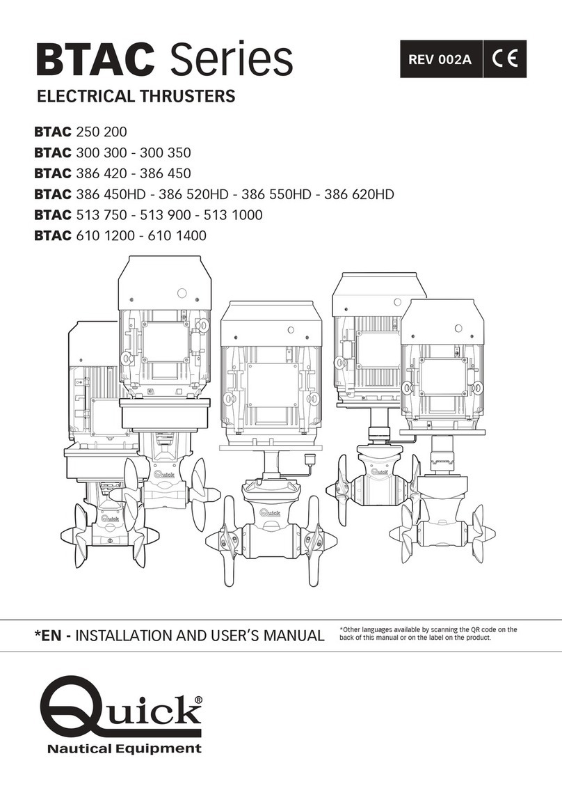
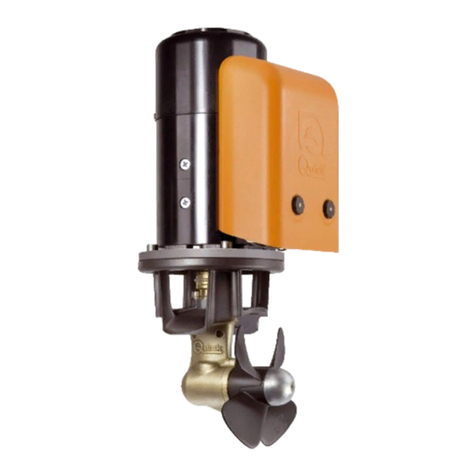
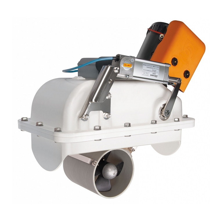
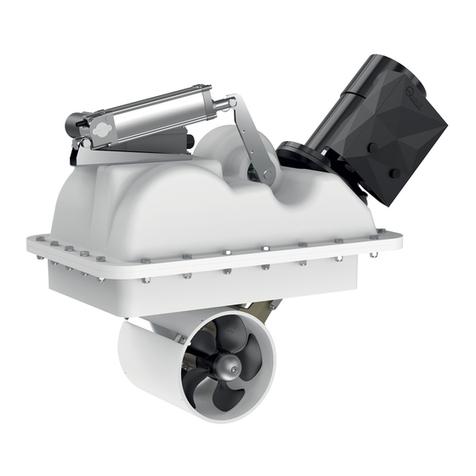
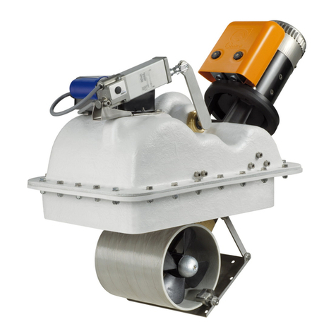
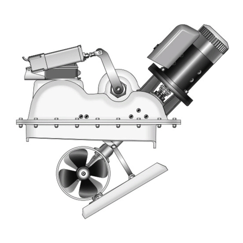
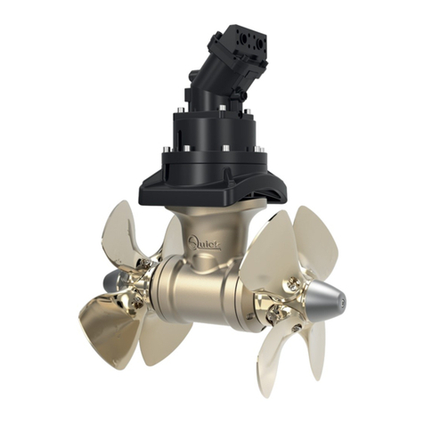
Quick BTAC Series User manual

ELECTRIC THRUSTERS
USER MANUAL IT pag. 3
BTAC
series
DOUBLE PROPELLER
REV 000A
BTAC250200 •BTAC300300 • BTAC300350 •BTAC386420 •BTAC386460 • BTAC 5131000


3INSTALLATION AND USE MANUAL BTAC SERIES - REV000A
BTAC Series EN
Index
1 - Information about the product Pag. 4
1.1 - Technical data Pag. 4
2 - Supplied parts Pag. 5
2.0 - Package contents Pag. 5
2.1 - Needed tools for installation Pag. 5
2.2 - “Quick®” recommended accessories Pag. 5
3 - Introduction Pag. 5
3.0 - Important notes Pag. 5
3.1 - Precautions for the installer Pag. 5
3.2 - Installation requirements Pag. 6
4 - Safety Pag. 6
4.0 - Warnings Pag. 6
5 - Installation Pag. 7
5.0 - Propellers Pag. 7
5.1 - Tunnel Pag. 8
5.2 - Thruster Pag. 9
5.3.0 - BTAC 250/300 gearleg and motor support ange Pag. 10
5.3.1 - BTAC 386 gearleg and motor support ange Pag. 11
5.3.2 - BTAC 513 gearleg and motor support ange Pag. 11
5.4.0 - BTAC 386 rilsan tube and oil tank Pag. 12
5.4.1 - BTAC 513 rilsan tube and oil tank Pag. 12
5.5 - Oil tank positioning Pag. 13
5.6 - BTAC 386/513 coupling/motor assembly Pag. 14
5.7 - Propellers tting Pag. 15
6 - Connection diagram Pag. 16
7 - Warnings Pag. 16
7.0 - Warnings Pag. 16
8 - Usage Pag. 17
9 - Maintenance Pag. 17
10 - Disposal of the product Pag. 17
11 - Spare parts Pag. 18
12 - Dimensions Pag. 21

4INSTALLATION AND USE MANUAL BTAC SERIES - REV000A
EN
BTAC Series
1 - Information about the product
MODELS BTAC386420 BTAC386460 BTAC513100
N° Propellers 2 contra-rotating NIBRAL 2 contra-rotating NIBRAL
Tunnel Ø
386 mm (15” 13/64)
513mm (20” 13/64)
Motor type Four-pole electric motor
Motor power 30 kW 37 kW 75 kW
Voltage 400/690 V 400/690 V 400/690 V
Thrust 420 kgf (925 lb) 460 kgf (1014 lb) 1000 kg (2205 lb)
Limit thickness values of
the tunnel
min. 8 mm - max 15 mm
(min. 5/16" - max 19/32")
min.12 - max 22 mm
(15/32" - 55/64")
Weight 304 kg (670.20 lb) 387 kg (853.19 lb) 742 kg (1636 lb)
MODELS BTAC250200 BTAC300300 BTAC300350
N° Propellers 2 contra-rotating PLASTIC 2 contra-rotating NIBRAL
Tunnel Ø
250 mm (9" 27/32) 300 mm (11" 13/16) 300 mm (11" 13/16)
Motor type Two-pole electric motor
Motor power 15 kW 15 kW 22 kW
Voltage 400/960 V 400/690 V 400/960 V
Thrust 200 kgf (441 lbs) 300 kgf (661 lbs) 350 kgf (771 lbs)
Limit thickness values of
the tunnel
min. 6,5 mm - max 11 mm
(min. 1/4" - max 7/16")
min. 9,5 mm - max 13,5 mm
(min. 3/8" - max 17/32")
Weight 160 kg (353 lb) 167 kg (368 lb) 216 kg (476 lb)
BEFORE USING THE THRUSTER, CAREFULLY READ THIS USER MANUAL.
IF IN DOUBT, CONTACT YOUR NEAREST QUICK®DEALER
QUICK® RESERVES THE RIGHT TO INTRODUCE CHANGES TO THE EQUIPMENT AND THE CONTENTS OF THIS MANUAL WITHOUT PRIOR NOTICE. IN CASE OF DISCREPANCIES OR
ERRORS BETWEEN THE TRANSLATED TEXT AND THE ORIGINAL ITALIAN TEXT, PLEASE REFER TO THE ITALIAN TEXT
F
1.0 - Technical data

5INSTALLATION AND USE MANUAL BTAC SERIES - REV000A
BTAC Series EN
2 - Supplied parts
2.0 - Fornitura di serie e materiale incluso nella confezione
• AC Thrusters
• Drilling template
• Gasket
• O-ring (for assembly) - (only 250-300-513)
• User’s manual
• Conditions of warranty
2.1 - Needed tools for installation
BTAC 250 • Drill and drill bits Ø 11 mm (7/6”) • Hole saw Ø 46 mm (1” 13/16)
• Hex keys 4 mm, 5 mm, 8 mm e 10 mm • wrench 24 mm
BTAC 300 • Drill and drill bits Ø 15 mm (19/32”) • Hole saw Ø 53 mm (2” 3/32)
• Hex keys 4 mm, 5 mm, 8 mm e 12 mm • wrench 27 mm
BTAC 386 • Drill and drill bits Ø 16 mm (4" 5/8) • Hole saw Ø 120 mm (4" 23/32)
• Hex keys 4mm, 6mm 5 mm, 8 mm e 14 mm • wrench 27 mm
BTAC 513 • Drill and drill bits Ø 18 mm (45/64”) • Hole saw Ø 140 mm (5” 33/64)
• Hex keys 5 mm, 8 mm e 14 mm • wrench 32 mm
2.2 - Quick®recommended accessories
• TCD 1022 • AC POWER
• TCD 1062 • INVERTER
• TCD 1042 • AJ1
• TCD 1044 • PCS TJ1
• PCS TJ2
• PCS TJ3
• PCS DTW
3 - Introduction BTAC series
This document contains the instructions that are necessary for boat manufacturers and
marine equipment installers to assemble and commission the Thrusters.
Warning symbol concerning hazardous
situations.
Caution symbol to avoid direct or
indirect damage to the product.
This manual contains Warning and/or Caution symbols that are important for safety.
Comply with the recommendations provided herein.
3.0 Important notes
F
PROCEEDING WITH THE INSTALLATION IN GOOD LIGHT CONDITIONS.
We recommend using an appropriate personal protective equipment.
Quick®thrusters are not suitable for installation in potentially explosive environments and/or atmospheres.
Assembly and subsequent checks or repairs must only be carried out by qualied personnel.
3.1 Precautions for the installer

6INSTALLATION AND USE MANUAL BTAC SERIES - REV000A
EN
BTAC Series
3 - Introduction
4 - Safety BTAC series
3.2 - Installation requirements
It is strongly recommended to entrust a professional with the preparation and positioning of the tunnel in the hull.
These instructions are generic and do not show by any means the details of the operations of preparing the thruster, which
falls under the competence of the shipyard. In case of problems caused by a defective installation, the installer will be held
responsible.
Despite all components and moving mechanical parts are of high quality, the correct installation of the propulsion unit is funda-
mental for a safe and efcient use of the boat, as well as of the propulsion unit itself.
Please note that the installation of such unit is an operation requiring experience and technical competence. It is recommended
to entrust the installation to competent staff and to consult the manufacturer or naval architects to fully evaluate the entity
of the work.
THE PRODUCT MUST BE DISCONNECTED FROM THE HYDRAULIC SYSTEM BEFORE INSTALLING OR PROVIDING
MAINTENANCE.
Quick® takes no responsibility regarding the inadequate connection of the users to the hydraulic system
and to the safety of itself.
4.0 - Warnings
• Quick®Thrusters have been designed and constructed only for nautical use.
• Do not use these appliances for other uses.
• Quick®shall accept no responsibility for direct or indirect damages caused by improper use of the
appliance or an improper installation.
• The Thruster is not designed to maintain loads generated in particular atmospheric conditions (storms).
• We recommend that you entrust the preparation and the positioning of the tunnel on the hull to a skilled
professional.
• These are generic instructions and do not give details of the preparatory operations for installing the tunnel,
which falls under the competence of the boatyard. The installer shall bear full responsibility for any problems
caused by defective installation of the tunnel.
• Do not install the electric motor near easily inammable objects.

7INSTALLATION AND USE MANUAL BTAC SERIES - REV000A
BTAC Series EN
5 - Installation
minimum 0,75 times the
tunnel Ø
BARYCENTER
L 1
L 2
A A
• The position of the tunnel will depend on the
interior and exterior shape of the boats bow.
• Optimal positioning of the tunnel will be in the
bow and as low as possible and at a distance
from the waterline which should be at least 0,75
times the tunnel diameter.
• To avoid cavitation in the propeller, the tunnel
must be positioned as low as possible in the
hull.
• The lever effect in the boat is proportional to
the increase of the distance (L1 and L2) between
the barycentre and the position of the tunnel A
and B.
• An increase in the length of the tunnel increases the effect of the loss of charge, decreasing the nominal driving force.
• For a correct use of the thruster we suggest a maximum length of 3-4 times the tunnel diameter and a minimum length of
1,5 times the tunnel diameter. To limit efciency loss it is acceptable a length that is six times the tunnel diameter.
FFor greater lever effect prefer position B
to position A.
5.0 - Propellers
MINIMUM 1,5 TIMES
TUNNEL Ø
MAXIMUM 6 TIMES
TUNNEL Ø

8INSTALLATION AND USE MANUAL BTAC SERIES - REV000A
EN
BTAC Series
5 - Installation
5.1 - Tunnel
• The rounded ends of the tunnel limit the creation of turbulences and cavitations, improving performance of the propeller
thrust and reducing noise levels to a minimum.
• The force produced by the ow of the water when the boat is moving produces resistance on the rear face of the tunnel,
which is an area exposed frontally to the water ow.
To limit this phenomenon, prepare an indentation in the rear part of the tunnel. Otherwise, create a deector on the front
part of the tunnel.
• If the tunnel is near the waterline, it is advisable to t a grating at the end of the tube.
The grating must have vertical and as large as possible meshes to avoid contrasting the
propeller thrust.
The vertical meshes prevent the entry of most of the oating objects.

9INSTALLATION AND USE MANUAL BTAC SERIES - REV000A
BTAC Series EN
10 2 3 4 5 6 7 8 9 10
Fig. D Fig. E
Fig. F
BTAC 250/300 BTAC 386 BTAC 513
5 - Installation
5.2 - Thruster
SUPPORT
TUNNEL
HULL
Fig. A Fig. B
SUPPORT TUNNEL
Fig. C
D
• It is recommended to install the thruster with a support base; the motor is already equipped with support feet.
• FIG.A The AC motor must be installed on a separate support from the hull. The support must be dimensioned so as to with-
stand the weight and power specied (table on page 4).
• FIG.B The distance (D) between the tunnel centerline (gure B) and the motor support must allow correct alignment between
the drive axle and the gearbox shaft.
• FIG.C The angle between the two shafts (gearbox and engine) must not exceed +/- 1.5 degrees.
• To position the thruster in the tube, nd the halfway
point. Fig.D
• Use the ange to mark the centre of the holes on
the tube. Fig.E
• Fix the drilling template on the reference points, making su-
re they are aligned with precision at the half-way point of the
tube. FIG.F
N.B. All holes must be exactly aligned with the half-way
point of the tunnel, since tolerance between propeller
and tunnel is minimal.
• Take care that there are no resin residues in the contact
area between ange and tube; this could cause misalignment.
Any resin residues and any other hindrance to correct contact
must be removed by sandpaper.
F

10 INSTALLATION AND USE MANUAL BTAC SERIES - REV000A
EN
BTAC Series
5 - Installation
Fig.G
• Insert two o-rings into the special
seats inside the ange.
Fig.G BTAC 250/300
5.3.0 - BTAC 250/300 Gearleg and motor support flange
SILICONE
• Proceed with tting the gearleg with
the special seal gasket.
• For further protection against the entry
of water, apply silicone for nautical
use around the point of contact between
ange and tube.
• Fasten everything to the ange using
the special screws.
• Grease the terminal part of the gearleg shaft; fit the
small key into its seat.
• Insert the elastic joint in the terminal part of the
gearleg shaft.
• Insert the motor onto the elastic joint. Secure with
four screws and four washers.
• Grease the terminal part of the gearleg shaft.

11INSTALLATION AND USE MANUAL BTAC SERIES - REV000A
BTAC Series EN
5 - Installation
5.3.1 - BTAC 386 Piede del riduttore e la flangia di supporto motore
5.3.2 - BTAC 513 Gearleg and motor support flange
• Fig.F Proceed with tting the gearleg. For further protection against the entry of water, apply silicone for nautical use around
the point of contact between ange and tube. Fasten everything to the ange using the special screws.
• Grease the terminal part of the gearleg shaft; t the small key into its seat.(g.2)
• Proceed with tting the gearleg with the special seal gasket.
• For further protection against the entry of water, apply silicone for nautical use around the point of contact between ange
and tube.
• Fasten everything to the ange using the special screws.
g.I g.E g.F
SILICONE
• Fig.I Apply to the gearleg the special seal gasket.
• Fig.E Remove the lid on the gearbox and insert the connection
to subsequently connect the oil tank.Screw on and turn the
connection’s head towards the center, in order to ease the cou-
pling with the ange.
SILICONE

12 INSTALLATION AND USE MANUAL BTAC SERIES - REV000A
EN
BTAC Series
5 - Installation
A. Remove the screw and the gasket
B. Screw the tting supplied
C. Insert the rilsan tube into the tting and into the tank
5.4.0 - BTAC 386 Rilsan Tube and oil tank
5.4.1 - BTAC 513 Rilsan Tube and oil tank
RILSAN TUBE
TANK
B
C
A
SCREW
GASKET
FITTING
• Insert the Rilsan pipe into the tting with the special
expansion tank.
• After xing the ange, turn the tting clockwise and
align it with the ange opening.

13INSTALLATION AND USE MANUAL BTAC SERIES - REV000A
BTAC Series EN
> 0,2 x d
d
Tunnel center line
Waterline
AIR
OIL
1
POSITION THE PIPE CORRECTLY, IN ORDER TO PREVENT “SIPHON” EFFECT.
THE TANK MUST ALWAYS END UP IN VERTICAL POSITION.
5 - Installation
5.5 - Oil tank positioning
• Fit the oil tank (1) above the waterline by at least 20% of the distance (d) from the waterline to the centre of the tunnel. This is
for ensuring enough overpressure of oil in the gearhouse.
• Fill the oil tank with gear oil type GL-5

14 INSTALLATION AND USE MANUAL BTAC SERIES - REV000A
EN
BTAC Series
5 - Installation
5.6 - BTAC 386/513 Coupling/Motor assembly
1 - Grease the end part of the reducer and insert the lower
half-joint, fix it with an elastic ring, and the elastic coupling in
the end part of the reducer foot shaft.
2- BTAC 386: Tighten the coupling screw the lower elastic joint.
2- Lubricate the end of the motor shaft and mount
the upper half-joint.
BTAC 386
BTAC 386
BTAC513
2
3 - Mount the motor on the gearleg and fix it to the support.
4 - Tighten the coupling screw, hold down towards the gearleg.

15INSTALLATION AND USE MANUAL BTAC SERIES - REV000A
BTAC Series EN
5 - Installation
LOCTITE
A
C
DE
F
G
B
5.7 - Propellers fitting
ONLY Ø513
WARNING: Once the assembly is over, make sure that the propellers are exactly positioned at the centre of the
tunnel.
Insert the drive pins Ainto the holes of the gearleg shafts B, assemble the propellers Cinto the gearbox , making it
fit in correctly with the drive pins A, fix the propellers with the self-braking nuts D, (and tight screw E, ONLY Ø513) .
The anodes Fmust be locked with the screws Gsoaked with building adhesive (such as Loctite).

16 INSTALLATION AND USE MANUAL BTAC SERIES - REV000A
EN
BTAC Series
6 - Connection diagram
3
380...690 Vac
F
Use shielded cables to connect the inverter
to the motor.
*this data refer to S3 operating mode (periodic intermittent duty) - for any modification please contact Quick
MOTORE
MODEL MOTOR
POWER VOLTAGE INVERTER
POWER
ABSORPTION ON
GENERATORS*
BT250AC200 15 kW 400 V 15 kW 19 kW
BT300AC300 15 kW 400 V 15 kW 21 kW
BT300AC350 22 kW 400 V 22 kW 27 kW
BT386AC420 30 kW 400 V 37 kW 35 kW
BT386AC460 37 kW 400 V 37 kW 40 kW
BT513AC1000 75 kW 400 V 75 kW 90 kW
7 - Warnings BTAC series
NOTE: the bow thruster must be installed with
the RH propeller on the right-hand side of the
gearleg (see gure).
RH
WARNING: This thruster is not designed for a continuous use. It is equipped with protections which limit its operation at
a maximum time span, as reported on the controls’ manual.
It is strongly forbidden to bypass or modify such protections in order to increase the operating time span, under pain of
voiding the warranty and thus lifting any responsibility from Quick
WARNING: Make sure no swimmers or oating objects are in the vicinity before switching on the thruster.
WARNING: There must not be ammable materials in the peak or in the area where the Thruster motor is.
WARNING: Do not operate the bow thruster out of the water for more than 10 seconds.
WARNING: During docking, it is recommended not to leave in the water any free rope, which may be sucked in by the propellers,
thus leading them to break.
7.0 - Warnings

17INSTALLATION AND USE MANUAL BTAC SERIES - REV000A
BTAC Series EN
8 - Usage
GEARLEG FLANGE DISASSEMBLY 386
A) Dismantle the various components of the motor (1-2-3-4-5).
B) To force the detachment of the gearleg ange (6) from the
tunnel, use 4 screws M12x80.
4
5
6
2
3
1
A
B
9 - Maintenance BTAC series
Start-up happens following activation of a PCS panel.
Quick®thrusters are made in materials that are resistant to the sea environment: In any case, it is indispensable
to periodically remove deposits that form on the outer surfaces to avoid corrosions, interruptions and consequent system
inefciency.
WARNING: make sure that the power supply to the electric motor is not switched on when maintenance operations
are carried out.
Dismantle once a year, following the points below:
• Clean propellers, tunnel and gearleg.
• Replace the anodes (carry out this operation more often if needed).
• Replace the propellers if damaged or worn out.
• Check the tightness of all screws.
• Ensure that there is no water seepage inside.
• Check that all electrical connections are well tightened and oxide-less.
• Check that the batteries are in good conditions.
• Remove the graphite residues resulting from the normal motor brushes use.
WARNING: do not paint the anodes, the sealings and the gearleg’s shafts where the propellers are lodged.
ACCORDING TO THE USE WE RECOMMEND CHECKING PERIODICALLY THE OIL SEALS AND IF NECESSARY REPLACING THEM.
10 - Disposal of the product BTAC Series
During the installation, also at the end of product lifetime, the disassembly and scrapping operations must be performed
by qualied personnel.
This product is made up of different types of material, some of which can be recycled while others must be disposed of.
Seek information on the recycling and disposal systems envisaged by the local regulations in your area for this product cate-
gory. Some parts of the product may contain polluting or hazardous substances which, if disposed of into the environment, con-
stitute serious environmental and health risks.
As indicated by the symbol, it is forbidden to throw this product in the household wastes. Recycling according to
the methods envisaged by current legislation in your area, or return the product to the retailer when purchasing an
equivalent product.
Local legislation may include the application of serious nes in the event of improper disposal of this product.

18 INSTALLATION AND USE MANUAL BTAC SERIES - REV000A
EN
BTAC Series
11 - Spare parts
BTAC250200
BTAC250200
1
23
3
4
5
6
6
BTAC300300
BTAC300350
1
23
3
4
5
6
6
BTAC300300 - BTAC300350
N°.DESCRIPTION CODE
1 OSP HALF-JOINT BTAC 250 MOTOR KIT FVSGG250AC00A00
2 OSP KIT FLANGE BT 250 FVSGFLBTQ250A00
3 OSP GEARLEG KIT BT 250 FVSGGBBT2500A00
4 OSP KIT PROPELLER D250 RH FVSGEL250R00A00
5 OSP KIT PROPELLER D250 LH FVSGEL250L00A00
6 OSP KIT ANODES PROPELLER BT 250 ALL FVSGANBTQ25AA00
N°. DESCRIPTION CODE
1 OSP HALF-JOINT BTAC 300 MOTORE KIT FVSGG300AC00A00
2 OSP KIT FLANGE BT 300 FVSGFLBTQ300A00
3 OSP GEARLEG KIT BT 300 FVSGGBBT3000A00
4 OSP KIT PROPELLER D300 RH FVSGEL300R00A00
5 OSP KIT PROPELLER D300 LH FVSGEL300L00A00
6 OSP KIT ANODES FOR PROPELLER BT 300 ALL FVSGANBTQ30AA00

19INSTALLATION AND USE MANUAL BTAC SERIES - REV000A
BTAC Series EN
11 - Spare parts
BTAC386420
BTAC386460
BTAC386420 - BTAC386460
1
2
3
4
6
5
7
8
8
N°. DESCRIPTION CODE
1 OSP HALF-JOINT BTAC 386 MOTOR 37KW KIT FVSGG3863260A00
2 OSP HALF-JOINT BTAC 386 MOTOR 30KW KIT FVSGG3863255A00
3 OSP KIT EVEN TENSION DEVICE D109 BT 386 FVSGGPVP1090A00
4 OSP GEARLEG KIT BT 386 R2 FVSGGBBT3862A00
5 OSP KIT GASKET BT 386 R2 FVSGGRBT3862A00
6 OSP KIT PROPELLER D386L P740 COMP FVSGEL386L50A00
N°. DESCRIPTION CODE
7 OSP KIT PROPELLER D386R P740 COMP FVSGEL386R50A00
8 OSP KIT ANODES PROPELLER BT 386 ALL FVSGANBTQ38AA00

20 INSTALLATION AND USE MANUAL BTAC SERIES - REV000A
EN
BTAC Series
11 - Spare parts
BTAC5131000
1
2
3
3
5
4
4
6
N°.
DESCRIPTION
CODE
1 OSP KIT COUPLING BTAC 513-1000 FVSGG513100AC00
2 OSP KIT FLEX COUPLING D120 BT 513 FVSGGPVP1200A00
3 OSP KIT GEARBOX BT513 FVSGGBBT5130A00
4 OSP KIT ANODES PROPELLERS BT 513 ALL FVSGEL513R01A00
5 OSP KIT PROPELLER D513R P600 COMP FVSGEL513R40A00
6 OSP KIT PROPELLER D513L P600 COMP FVSGEL513L40A00
Other manuals for BTAC Series
1
This manual suits for next models
6
Table of contents
Other Quick Outboard Motor manuals

Quick
Quick BTQ Series Guide

Quick
Quick BTR1806512 User manual

Quick
Quick BTR140 Series Guide

Quick
Quick BTH 513 Guide

Quick
Quick BTQ1403012 User manual

Quick
Quick BTQ300 Series User manual

Quick
Quick BT185HY080 User manual

Quick
Quick BTR185 Guide

Quick
Quick BTQ110 series User manual

Quick
Quick BTQ140 User manual
Quick
Quick BTR185 User manual

Quick
Quick BTH 386 C00 Guide
Quick
Quick BT386HY455 User manual

Quick
Quick BTQ125 series Guide

Quick
Quick BT386AC420 User manual

Quick
Quick BTAC Series User manual

Quick
Quick BTQR1806512 User manual

Quick
Quick BTQ250 Series User manual

Quick
Quick BTR Series User manual

Quick
Quick BTR250 User manual