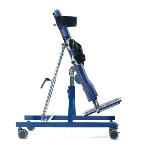
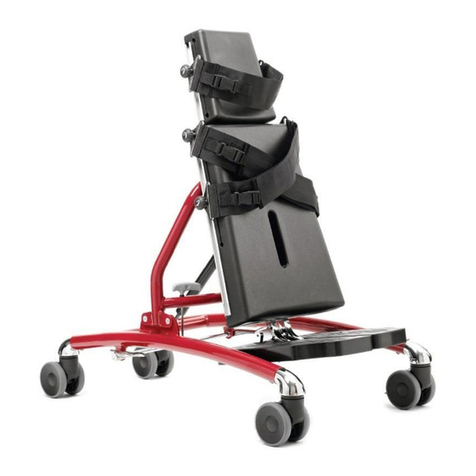
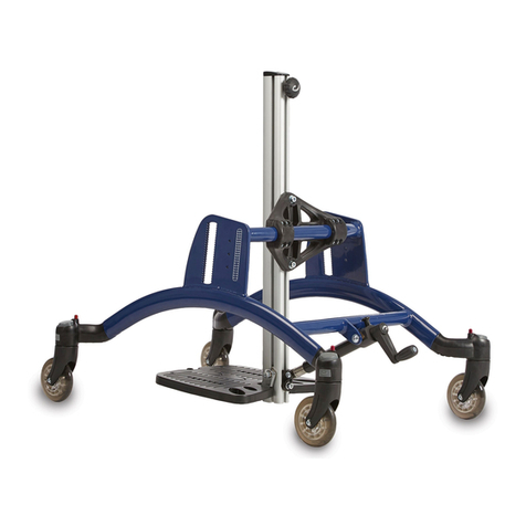
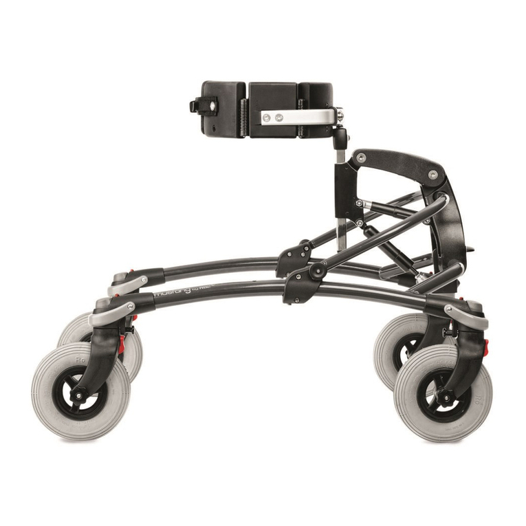
R82 x:panda Series User manual

English manual
G
B
2017-06 - rev. 17
TM
x:panda
© 2012 R82 A/S. All rights reserved.
The R82 logo and the x:panda chairs are trademarks of R82 A/S.

Pat. pend.
U.S. Patent Des. D598,680 S
Pat. Pend.
E
N
x:panda - Intended purpose
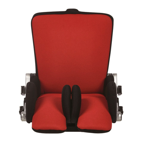
x:panda is a multiadjustable seat, delivered in 4 dierent sizes. Each seat adjusts in 3 dierent widths
and stepless in seat depth.
The back is dynamic, making it possible for the child to extend and push back against relatively light
resistance and then recover into the desired sitting position. Furthermore the back angles to make it
possible to place the child with either an open or closed hip angle. When angling the seat and the base
it is possible to create the desired working or resting position.
The x:panda is suitable for users needing an individual seating system and base, e.g. Children/young-
sters with:
• CP at GMFCS level III-V
• Strong extensor spasticity
• Developmental delays (physical or mentally handicapped)
The many adjustment possibilities and wide range of accessories makes it possible to adjust the seat
to an individual child’s need for comfort and support.
The seat ts on a variety of seat bases from R82, making it suitable for both indoor and outdoor use.
Indoor use:
• High-low:x indoor frame
Outdoor use:
• High-low:x outdoor frame
• Combi Frame:x
• Serval Buggy Frame
For transportation the x:panda is suitable for children in the weight range of 22 kg to specied max user
weight for transportation.
This manual will enable you to take full advantage of the many possibilities of the x:panda. Therefore,
we recommend that you read this manual before using the frame.
2

E
N
CONTENTS
x:panda - Intended purpose........................................................... 2
Instructions ............................................................................... 4-26
Declaration of Conformity............................................................ 27
R82 Warranty .............................................................................. 27
Safety .......................................................................................... 27
Disposal....................................................................................... 27
Service information...................................................................... 28
Washing....................................................................................... 28
Warewashing machine ................................................................ 28
Disinfection.................................................................................. 28
Accessories and spare parts ....................................................... 28
Service interval............................................................................ 28
Service Check List....................................................................... 28
Presales information.................................................................... 28
Technical data.............................................................................. 28
Producer...................................................................................... 28
Transport fittings on the Combi Frame ........................................ 29
Symbols....................................................................................... 30
Measurements............................................................................. 31
Transfer ....................................................................................... 32
Product identification ................................................................... 32
3

D
A
B
C
E
N
READY FOR USE
The x:panda is delivered so that it takes up
minimum space during transport. Follow the
instructions below to unpack the x:panda:
• Remove the x:panda from the box
• Adjust the back angle (A)
• Adjust the back height (B)
• Adjust the seat depth (C)
• Adjust the leg angle (D)
Further instructions can be found on page 5+6.
The x:panda is now ready for use once you have
fully read this manual.
4

A
B
A
B
D
C
E
N
BACK HEIGHT
ADJUSTMENT
Loosen the bolts (A) and (B) to adjust the height
of the back.
Fasten all bolts at the desired height.
Do not remove any of the bolts - only
loosen to adjust.
BACK RECLINE
Release the handle (A) to recline the back.
Warning 01 Squeezing hazard between the
back and frame/Push brace when adjusting
the back angle
Firmly grab hold and support the back of
the chair before releasing the handle to
prevent sudden recline.
The release handle is equipped with a security
lock (B). Turn the lock to the left and it is acti-
vated, turn it to the right and it is deactivated.
Always activate the lock after adjustment.
The back on x:panda has dynamic movement.
Move the small ring (C) up or down to adjust the
range of movement.
When reclining the back, please be carefull
not to get fingers caught between the gas
spring and the seat (D).
5

A
B
A
E
N
LEG SUPPORTS
- INDIVIDUAL
ADJUSTMENT
Angle and depth adjustment:
Loosen the bolt (A) to adjust. Fasten at the de-
sired position.
Width adjustment:
Remove the bolt (B) to adjust. Fasten at the
desired position.
Do not remove any of the bolts (A) - only
loosen to adjust.
HIP SUPPORTS
- INDIVIDUAL
ADJUSTMENT
Angle, depth and width adjustment:
Loosen the bolts (A) to adjust. Fasten at the
desired position.
Do not remove any of the bolts - only
loosen to adjust.
6

A
D
C
B
A
E
N
HEAD SUPPORTS
Mounting and height adjustment:
Loosen the handle (A).
Angle adjustment:
Loosen the screws (B) and (C) with a spanner.
Sideways adjustment:
Loosen the screw (D).
Fasten all screws at the desired position.
When adjusting the head support, please
be carefull not to get fingers caught bet-
ween the back of the chair and the head
support fiitting.
Warning 05 Squeezing hazard between the
head support and frame/pushbrace when
adjusting the back
BACK WIDTH
EXTENSION
ONLY SIZE 4
Mount the back width extension and fasten the
screws (A) on the back. Make sure the extension
is pushed all the way in before fastening.
7

A
A
B
E
N
UPPER ARM SUPPORT
FOR THE FIXED SIDE
SUPPORTS
The upper arm supports is developed as an
accessory to seats produced later than De-
cember 2008, i.e. for seats delivered before
this period, you will need a new set of side
supports in order to mount the upper arm
supports.
QUICK LOCKS FOR
FIXED SIDE SUPPORTS
Height adjustment:
Remove the bolts (A).
Place the side supports with quick locks in the
desired position and remount the bolts.
Width adjustment:
Pull the quick lock handle up (B).
Lock the handle down when the support is in the
desired position.
FIXED SIDE SUPPORTS
Height adjustment:
Remove the bolts (A).
Place the supports in the desired position and
remount the bolts.
Width adjustment:
Loosen the bolts (A).
Fasten at the desired position.
8

A
A
B
B
E
N
QUICK LOCKS FOR
SWING-AWAY SIDE
SUPPORTS
Height adjustment:
Remove the bolts (A).
Place the side supports with quick locks and
remount the bolts.
Width adjustment:
Pull the quick lock handle up (B).
Lock the handle in the desired position.
SWING-AWAY SIDE
SUPPORTS
Height adjustment:
Remove the bolts (A).
Place the supports and remount the bolts.
Width adjustment:
Loosen the bolts (A).
Fasten at the desired position.
Swing-away function:
Press the red button (B) to release.
The carer should check and oil (synthetic
oil) the swing away parts occationally - at
least every 3 months.
9

B
A
C
D
C
D
B
D
E
N
ARM REST
Height adjustment:
Loosen the screw (A) and move it into desired
height position. Fasten the screw.
Loosen handle/screw (C) to move the arm rest
into position. Fasten the handle/screw (hand-
tight).
Angling the arm rest cushion:
Loosen the handle (B).
Angling the arm rest bar (only size 1+2+3):
Loosen the handle/screw (C).
Adjust the arm rest cushion:
Loosen the screws (D) beneath the armpad.
When adjusting the arm rest, please be
carefull not to get fingers caught between
the chair and the armpad.
Do not carry the product by the armrests
10

A
C
B
AB
C
E
N
TRAY, TWO-ROD
SYSTEM
ONLY FOR SIZE 1+2+3
A) Mounting and depth adjustment
B) Width adjustment
C) Angling the tray, by angling the arm rests.
The tray can only be mounted on a x:panda
equipped with arm rests mounted at the
same height and angle.
Entrapment hazard:
Adjust armrests before an user is seated
in the product and the tray inserted
TRAY, SWING-AWAY
ONLY FOR SIZE 1+2+3
A) Mounting and depth adjustment
B) Width adjustment
C) Angling the tray, by angling the arm rests.
The tray can only be mounted on a x:panda
equipped with arm rests.
Entrapment hazard:
Adjust tray and armrest before an user is
seated in the product
11

A
B
A
A
E
N
GRIP HANDLE FOR
TRAY
ONLY FOR SIZE 1+2+3
A) Angle adjustment
The grip handle can only be mounted on
a x:panda equipped with tray.
TOYBAR FOR TRAY
ONLY FOR SIZE 1+2+3
A) Angle ajdustment
The toybar can only be mounted on a
x:panda equipped with tray.
ARM REST FOR TRAY
ONLY FOR SIZE 1+2+3
A) Depth adjustment
B) Angle adjustment
The arm rests can only be mounted on a
x:panda equipped with tray.
12

A
A
C
A
BC
D
B
E
N
VESTS & BELTS
All vests and belts with 25 mm strap can be
mounted on the seat. We recommend to use the
fixlocks or belt guidances on the chair.
Fixlocks:
Use the fixlock (A) mounted on the chair to fa-
sten and adjust all vests and belts. An extra 40
mm fixlock can be mounted on the size 4 seat
if needed (B).
Belt guidance:
Guide the beltstraps through the prepared slots
(C) in the seat.
FIXLOCK FITTINGS
To mount vests and belts the correct way, it might
be necessary to mount extra fixlock fittings. The
fittings are mounted on the top of the back and
are able to lift the straps away from the shoulders
of the user.
* Mount the fittings in the lower holes (A) to get
a higher mounting of the straps.
* Mount the fittings in the top holes (B) to get a
lower mounting of the straps.
* Mount the fittings as shown on drawing (C)
to get a larger distance between the fittings.
* Mount the fittings as shown on drawing (D) to
get a smaller distance between the fittings.
13

A
E
N
SEAT WEDGES
Depth adjustment:
Remove the seat cushion and release the wed-
ges from the velcro in the seat.
Flip up the velcro (A) and place the wedges at
the desired depth position. Replace the seat
cushion.
SEAT STRAP
Depending on the desired leg abduction the
seat strap is mounted in one of the three holes
in the seat.
Adjustment:
Flip up the strap in one of the sides and adjust
the length of the strap. Fold down the strap to
fasten with the velcro.
14

E
N
FOAM BACK PLATE
The foam back plate can be adjusted to fit the
gap beneath the back.
* If necessary, cut the foam plate with a knife
to make it fit the gap.
* Place the foam plate on the back.
LUMBAR SUPPORT
Remove the cushion to mount the lumbar sup-
port on the back
* Place the lumbar support in position
COVER PLATE
ONLY FOR SIZE 4
The cover plate fits the gap beneath the back.
* The cover plate is mounted in the slot in the
back
15

A
B
E
N
NON-DYNAMIC GAS
SPRING
ONLY FOR SIZE 1+2+3
The standard gas spring can be replaced with a
non-dynamic gas spring.
Loosen the handle (A) to angle the back.
Please be aware not to get your fingers
caught betweeen the gas spring and the
seat when angling (B).
FIXED ROD
The standard gas spring can be replaced with
a fixed rod.
16

A
B
E
N
X:PANDA MOUNTED ON
HIGH-LOW:X
To mount the seat:
The interface and the footrest bar must be
replaced on the old High-low frames.
Place the seat adapter in the interface and push
it all the way back, until it "clicks" into place.
Lock the red handle (B) to secure the stability
of the seat.
Do not use the first hole it „clicks” into. This
is just the „safety hole” which will „catch”
the seat if the knob accidently should pop
out of its correct hole.
To dismount the seat:
Unlock the red handle (B). Pull out the knob (A),
pull the seat forward, and lift at the same time.
17

A
2 x
2 x
E
N
MOUNTING THE SEAT
ON THE HIGH-LOW:X
SIZE 3
ONLY SIZE 3+4
Mount the x:panda seat directly on the High-
low:x size 3 frame.
* Lead the enclosed screws though the seat
frame (A) from below. Make sure the seat is
securely fastened before use.
* Remove the screws at dismounting
18

A
B
C
F
D
E
E
Size
1+2+3
Size 4
E
N
GROWTH FROM ONE
SIZE TO ANOTHER -
WIDTH ADJUSTMENT
Follow this description to perform a smooth
adjustment of the seat width. Also read the in-
structions on the next page concerning depth
adjustment.
Dismount the hip supports (A) at both sides.
Dismount the metalplate (B). Remove the 4 bolts
(C) and swing away the back.
Left chair side:
Pull the leg support forward but do not remove
any bolts not described.
Remove the bolt (D).
Remove the bolt (E).
Remount at the desired width position and re-
place the bolts (D) and (E). Do not fasten the
bolts completely.
Right chair side:
Remove the bolts (D) and (E) at the opposite
side of the chair.
Place the seat spacer (F).
Remount at the same width position as the op-
posite side and replace the bolts (D) and (E).
Remount the bolts (C).
Both chair sides:
Fasten all bolts (C) (D) and (E) at both sides of
the seat.
Do not loosen or remove any bolts not
described above.
To prevent at mix up of bolts, we re-
commend to keep the removed bolts
together with the removed part, e.g.
the hip supports.
The carer should check and tighten all
bolts at least every month.
19

A
B
E
N
GROWTH FROM ONE
SIZE TO ANOTHER -
DEPTH ADJUSTMENT
Follow this description to perform a smoothly
adjustment of the seat depth. Also read the in-
struction on the previous page concerning width
adjustment.
Remove the two bolts (A) at both sides of the
chair.
Take a firm hold of the backrest.
Remove the two bolts (B).
Remount at the desired depth position and re-
place and fasten the bolts (A) and (B).
Do not loosen or remove any bolts not
described above.
To prevent at mix up of bolts, we re-
commend to keep the removed bolts
seperated.
The carer should check and tighten all bolts
at least every month.
20
Table of contents
Other R82 Mobility Aid manuals