R82 buffalo User manual

buffalo
© 2007 R82 A/S. All rights reserved.
The R82 logo and the Buffalo are registered trademarks of R82 A/S.
TM
07.2007
English manual
G
B

2
G
B
GB Contents
Safety ................................................................................ 4
Guarantee.......................................................................... 4
Tools .................................................................................. 4
Maintenance...................................................................... 4
Ready for use .................................................................... 5
Straps & Foot supports...................................................... 6
Heel support, "Duck Foot" and frame extension................ 6
Chin Support and Side supports........................................ 7
Knee supports ................................................................... 7
Head support with nose hole............................................. 8
Pommel ............................................................................. 8
Extra cushion .................................................................... 9
Back support...................................................................... 9
Table ................................................................................ 10
Manual tilt ........................................................................ 11
Mounting the power tilt 1/2 .............................................. 12
Mounting the power tilt 2/2 ............................................. 13
Product identification ....................................................... 14
Measurements................................................................. 15
Technical data.................................................................. 16
Producer.......................................................................... 16
Distributor ........................................................................ 16

Pat. pend.
3
G
B
Buffalo
Congratulations on purchasing the Buffalo. The Buffalo is a tiltable standing
frame from R82. We are convinced, that it will fully live up to your expec-
tations.
The Buffalo has been developed with an optimum of security and value in
mind. The Buffalo is for indoor use only, and is to be used on a levelled,
non tilting surface only.
This manual has been made to help you gain as much use from the Buffalo
as possible.
GB

4
G
B
safety
The Buffalo has earned the CE-mark. This certifies that it meets all relevant Euro-
pean safety requirements.
The durability of this product is 7 years when it is used on a daily basis. Hereafter
we recommend that the product should be renovated (by R82 personnel) to extend
the lifetime.
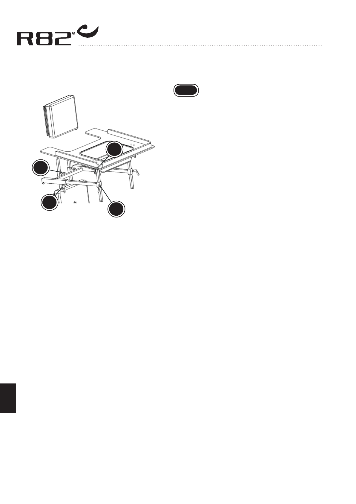
Activate the brakes before placing the user on the tilttable. To obtain the best
control, place the user on the tilttable when it’s in horizontal position. The user
must be fastened securely before tilting into a vertical position.
Remove the CE-mark, when rebuilding the product or when using other than
original R82 spare parts.
Never leave your child unattended in this product. Ensure permanent super-
vision by an adjult. Incorrect use of the Buffalo, may cause serious injury to
the user. Take care that all the fixations and adjustments are placed and fitted
correctly and check it on a regular basis.
We do not recommend moving the Buffalo with the child in it over long distan-
ces, over joints in carpets, over uneven surfaces or outside.
Guarantee
Any R82 product, bought with an R82 dealer, includes a guarantee against defects
in types and materials. There is a 5 years guarantee on frame breaks.
The guarantee is given by the R82 dealer or subsequent R82 representative.
The guarantee can only be sustained if the R82 product is in use in the same
country as produced for. The guarantee does not cover accidental damages,
including damages caused by misuse or neglect. The guarantee stops if the se-
rial number is removed, or if the product is repaired or changed by others than
authorized R82 staff.
tools
Use the enclosed 6 mm Allen key to perform the adjustments where described in
this manual.
MaintenanCe
The Buffalo functions without maintenance, but it is recommended to clean
the frame frequently. Do not use any cleaning materials containing chlorine
or methylated spirit.
The carer should check and oil the swing away parts occasionally. We re-
commend to use a synthetic teflon oil.
Do not expose the gasspring to pressure, high temperatures or perforation.
Adjustments which are not described in this manual, must only be made by
authorized R82 personnel.
GB
GB
GB
GB

A
B
5
G
B
GB ready for use
The Buffalo is delivered in parts and folded to
make it take up as little room as possible during
transportation. To make your Buffalo ready for
use, please follow the below description.
* Lift the standing frame out of the box and
remove the plastic bag. The foot plates and
straps are included in the small box.
* Mount the foot plates in the vertical bars and
fasten with the handles (A) on the sides.
* Mount the straps in the slots on each side of
the basis plate. Fasten with the finger screws
(B).
* Angle the Buffalo into wanted position. See
instruction on page 11.
Your Buffalo is now ready for use.

A
B
C
A
C
B
6
G
B
straps & foot
supports
The height of the straps is adjustable. Use the
handle on the side (A).
Adjust the height (B) and angle (C) of the foot
supports as shown by using the black levers.
GB
Heel support, "duCk
foot" and fraMe
extension
Heel support (A) and ‘duck foot’ (B) are mounted
alike. They are placed in the slots in the foot
plates as shown below and fastened with the
handle.
Mounting the frame extension (C):
1. Pop out the stopper and remove the wheel.
2. Insert the extension.
3. Fasten the extension and the wheel with the
screws.
4. Insert the stopper.
GB

B
A
D
C
C
D
A
B
7
G
B
CHin support and
side supports
Mount the chin support on the long, through bars
as shown. Fasten carefully (A).
Side supports. Place the fittings in the slots as
shown (B) and fasten in the desired height with
the Allen key (C).
Then place the side supports in the fittings.Adjust
sideways and fasten with the black lever (D).
GB
knee supports
Place the fitting in the slot (A) and fasten in the
desired height with the Allen key.
Then place the bar (B) in the fitting and fasten
with the handle (C).
Mount the knee support bars in the fittings and
fasten with the Allen key.
The knee supports adjust sideways. Use the
finger screws on the back (D).
GB

A
A
B
8
G
B
Head support witH
nose Hole
Dismount the old fittings on the back of the chest
plate (A). Use a 4 mm Allen key (6 mm if Buffalo
size 3). Mount the new 3-pipe-fittings in the same
holes on the plate.
Place the bar with the head support in the mid
pipe and fasten with the handle (B).
GB
poMMel
Place the pommel in the slot centered on the
board. Fasten from behind with the Allen key (A).
GB

C
D
A
B
9
G
B
extra CusHion
Remove the upper trunk support. Move the two
long throughbars to be able to fit both the exten-
sion pieces and the upper trunk as shown.
Lead the bars through the extra cushion and the
trunk support.
Fasten with the handle (A)
GB
BaCk support
Remove the two long go-through-bars. Place the
mounting brace for the back support and take the
through-bars back down through the mounting
brace and into place (B)
Fasten the mounting brace on the go-through-
bars with the handles. Fit the bars of the back
support in the mounting brace and fasten with
the Allen key (C).
The pad on the back support can be adjusted si-
deways (D). The vertical bar with the pad swings
up and away, making it easy to get in and out
of the Buffalo.
GB

A
B
C
D
10
G
B
taBle
To mount the table, start by removing the upper
trunk support. Then place the table on the long
through bars (A), and place the upper trunk sup-
port again. Use the Allen key to adjust height
(B) and depth (C). Use the black lever to adjust
the angle (D).
The table can be turned around and used for
front lying users. Dismount the horizontal bars
(C) and remount them in the holders from the
opposite side.
GB

C
B
A
D
11
G
B
GB Manual tilt
The Buffalo size 1 with manual tilt angles from
vertical into the horizontal position by pressing the
foot pedal (A) down.
It is important to hold on to the tilt table
before the foot pedal is activated and while
the angle is being adjusted.
The angle adjustment function can be
locked to prevent it from tilting by mistake.
The small metal part (B) on the reverse
side of the foot pedal can be turned to ac-
tivate/deactivate the safetylock as shown
in the diagram.
The Buffalo size 2 and 3 with manual tilt ang-
les from vertical into the horizontal position by
loosening the handle (C). The security lock (D)
will hold the tilt table.
Hold on to the tilt table and pull out the security
lock (D).
Slip the security lock when the tilt table is in the
required position.
Fasten the handle (C) securely
It is important to hold on to the tilt table
before the security lock is released and
whilst the angle is adjusted.

A
B
1
2
3
12
G
B
MountinG tHe power
tilt 1/2
This is to show how you mount Power Tilt on a
standard Buffalo. Power Tilt is only available for
Buffalo size 2 & 3.
1) In order to attach the control box, fasten the
plate in the holes. Then attach the control box
to the plate.
A = power cable (220 V)
B = remote control cable
2) Dismount the bar for the manual tilt at the top.
Use an Allen key and a 13 mm fork wrench.
3) Then dismount the bar for the manual tilt
below. Use an Allen key and a 13 mm fork
wrench.
GB

4
5
6
C
13
G
B
MountinG tHe power
tilt 2/2
4) The fitting for the manual tilt bar has to be
exchanged with the new one.
5) Place the bar for the power tilt in the new
fitting. Use an Allen key and a 17 mm fork
wrench.
6) Place the bar for the power tilt in the fitting
below. Then connect cables from the electric
motor and the remote control to the control
box. C = control box cable
Charging the battery:
For an optimum lifetime of the battery it must
charge for at least 12 hours before use.
1) Connect the charger to the socket.
2) When the battery box is plugged it starts
charging.
3) Charge the battery.
To gain the optimal profit of the angle adjust-
ment function, the batteries must be charged
every night. The batteries can not be charged
too much, but do not ever let them drain com-
pletely.
Do not leave the user alone with access
to the remote control and do not leave
the remote control within reach of other
children.
The power angling is possible during the
charging.
GB

A
B
Dato: 31-01-02 Belast: kg
SN: 0840-01-111878-001
Varenr: 880003
5707292 134158
Parallelvej 3
DK-8751 Gedved
A
B
14
G
B
produCt
identifiCation
A) Serial number
The label is placed on the right side of the
frame on the inside of the bar.
B) Manufacturer
The label is placed on the right side of the
frame on the outside of the bar.
GB

15
G
B
MeasureMents
Size 1 Size 2 Size 3
cm (inch) cm (inch) cm (inch)
Height, vertical (HV) 85 (33¼") 106 (41¼") 135 (52¾")
Height, horizontal, wo/power (HH) 60-63 (23½-24½") 65 (25¼") 72 (28")
Height, horizontal, w/power (HH) - 67 (26¼") 74 (28¾")
Height, from foot plate (H) 75-115 (30-45") 90-135 (35-53") 125-170 (49-67")
Frame width (W) 49 (19") 54 (21") 62 (24")
Frame length (L) 70 (28") 85 (33¼") 111 (44")
Angling 0-90° 0-90° 0-90°
Chest plate width 26 (10¼") 32 (12½") 36 (14")
Chest plate height 24 (9¼") 27 (10½") 36 (14")
Basis plate width 31 (12") 37 (14½") 46 (18")
Basis plate height 44 (17¼") 56 21¾") 81 (31½")
Weight, wo/power 19 kg (42 lb) 23 kg (51 lb) 30 kg (66 lb)
Weight, w/power - 29 kg (64 lb) 36 kg (79 lb)
Max load 50 kg (110 lb) 70 kg (154 lb) 100 kg (220 lb)
H
HH
WL
GB
HV

16
G
B
teCHniCal data
Frame: Chromed steel or powder lacquered steel
Upholstery: Wooden plate with fire-resistant foam covered with fireresistant artificial leather
produCer
R82 A/S
Parallelvej 3
8751 Gedved
Denmark
distriButor
Please find your distributor on www.r82.com
GB GB
GB
Other manuals for buffalo
1
Table of contents
Other R82 Mobility Aid manuals
Popular Mobility Aid manuals by other brands

Arjo
Arjo MAXI MOVE Operating and Product Care Instructions

aidapt
aidapt VP179 Usage and maintenance instructions

uniprox
uniprox JT05 instruction manual

RoMedic
RoMedic SystemRoMedic LiftSeat manual

Dolomite
Dolomite FUTURA operating instructions

Permobil
Permobil ROHO DRY FLOATATION Cushions Operation manual

Besco Medical
Besco Medical SPRING CROSS COUNTRY instruction manual

Guardian
Guardian MDS86012CHRG manual

Invacare
Invacare 1073913 Assembly, installation and operating instructions

Rehabmart
Rehabmart Trustcare Let's Go Service manual

GDP Research
GDP Research Miniguide Settings Quick Reference

made for movement
made for movement Innowalk troubleshooting guide