8
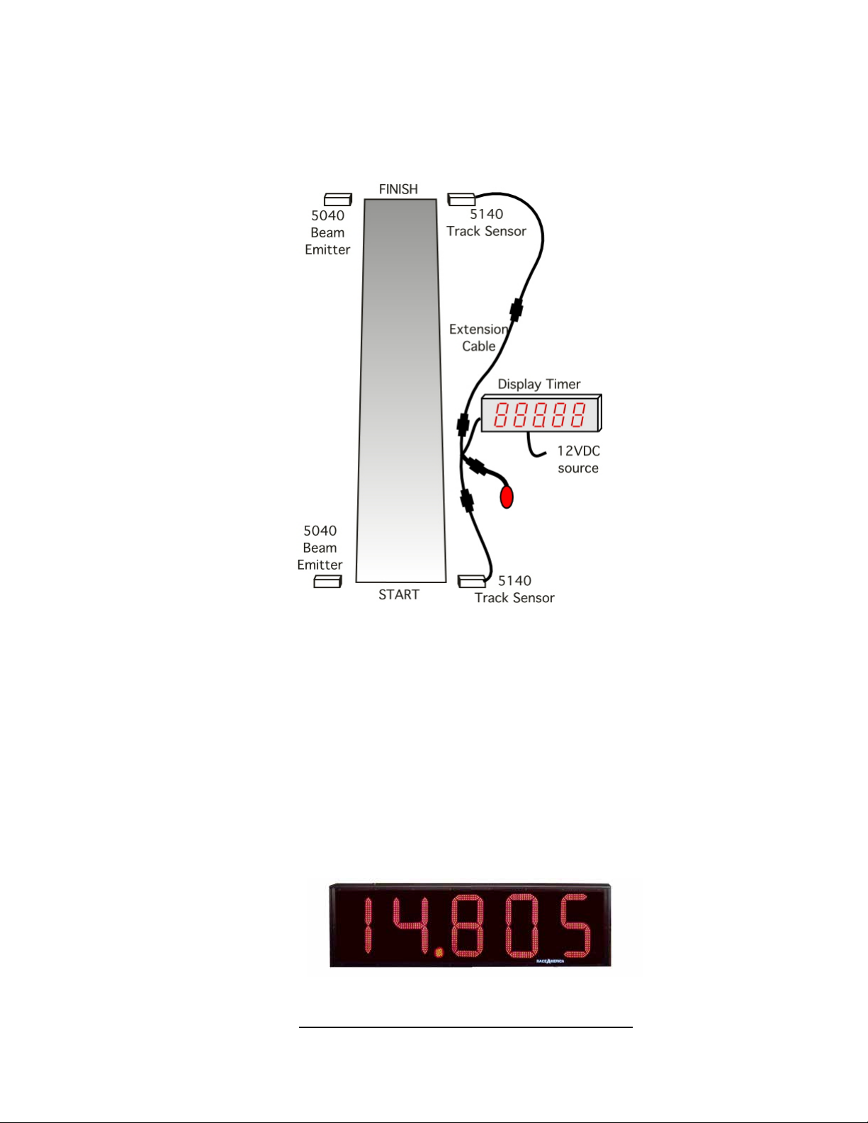
RaceAmerica Model 6632E Display Timer
POWER-ON SELF-TEST
When the 6632E power source is connected,
the display timer begins an internal self-test and
external visual check of the display segments.
The self-test begins by stepping through each
segment of all ve digits, one segment at a time
including the decimal point which exists to the
right of the second digit. The self-test continues
by sequentially illuminating each segment until
all segments and the decimal point are on. The
self-test continues by drawing a square frame by
sliding a small square from left to right, then down
and right to left. The square then collapses and the
revision level of the code (eg [-SEA0]) running
in the microprocessor is displayed, then [rEAdy]
scrolls in from left to right and blanks out. The
display advances to Alignment Mode.
When the 6632E power source is connected
while depressing the push-button, the display
timer enters the conguration menu by displaying
[-CFG-] until the button is released. The display
will ash one of the four display formats. Press/
release the button to see another format and
Press/hold the button to select the desired format.
The formats display as heir maximum times
with colons and decimal points as shown in the
specications: [99.999, 999.99, 99:59.9, 99:59].
When the button is released the display will show
[88881] which is the brightest display level; press/
release the button to cycle through four levels (1,
3, 5 and 7). Press/hold to select the desired level
and the timer will begin the self-test as described
above. Repeated power ups will default to the
last selected display format and brightness level 1.
ALIGNMENT MODE
On initial system power-up, the system
automatically enters Alignment Mode; the display
shows Align [ALIGn] briey, then [-S-F-] is
displayed indicating the START and FINISH
sensor/emitter pairs followed by [0S-F0].
If the Beam Emitter and Track Sensor are
operating properly and aligned, the ‘0’ digit will
not change. If the Beam Emitter and Track Sensor
are not properly aligned, the ‘0’ digit for each
emitter/sensor pair will count (1-2-3....8-9-1-2...)
slowly if slightly out of alignment or continuously
if they are not functioning properly or way out
of alignment. Once the emitter/sensor pair are
aligned properly, the digit will stop counting. If
the alignment is off a little or intermittent, the digit
for that emitter/sensor pair will count when they
oat out of alignment.
To maximize the alignment of the emitter/
sensor pairs, it is suggested to rotate the beam
emitter slowly left and right until out of alignment,
to detect the left/right limits of alignment.
Viewing the display to establish these limits will
help establish the extremes of the emitter/sensor
alignment. This technique will determine the
maximum lateral detection angle. Rotating the
beam emitter up and down until out of alignment
determines the maximum vertical detection angle.
Once these extremes are established, position
the beam emitter in the center of the left/right
detection angle and up/down detection angle.
Repeat this same process with the other Beam
Emitter and Track Sensor. This will maximize
the alignment accuracy.
When both sensors are aligned, press the
button to exit alignment mode and enter Run
Mode. To return to alignment mode, press
and hold the button until the Align sequence is
displayed.