Rise VIGILANT 500 User manual
VIGILANT 500
Manuale di installazione
Installation manual
Installationsanleitung
Manuel d'installation
Manual de instalación
IDissuasore di sosta e passaggio
Brevettato
Patented
Made in Italy
L8542001 - Rev.00
GB Parking and passage rising bollard
D
Poller gegen unrechtmäßiges Parken und Durchfahren
F
Borne escamotable anti-stationnement et anti-accès
EDisuasor de tránsito de aparcamiento y de paso

VIGILANT - rev.00 - 3
Il sottoscritto Paolo Peruzzo, legale rappresentante della ditta Rise S.r.l. - Via del Capitello, 42 - 36042 Marano Vicentino
(VI) - in qualità di costruttore, dichiara che il prodotto:
VIGILANT 500
è conforme in tutte le sue parti alle Direttive:
- Direttiva EMC 2004/108/CE
- Direttiva Bassa Tensione 2006/95/CE
e alle Norme Tecniche: EN 124:1995
come da veriche effettuate da: ECO Certicazioni S.p.A., via Mengolina, 33 - 48018 Faenza (RA)
Organismo Noticato n. 0714
Marano Vicentino, 15/03/2009.
Il legale rappresentante
IDichiarazione di conformità

VIGILANT - rev.00 - 3
I
Informazioni generali e speciche tecniche
Vi siamo grati per aver scelto uno dei nostri modelli Vigilant di dissuasori automatici retraibili.
Tutti gli articoli della gamma Rise sono il frutto di una lunga esperienza nel settore degli automatismi meccanici ed elettronici.
Proprio per questo, oggi siamo in grado di offrire dei dissuasori automatici estremamente afdabili che, grazie alla loro potenza,
efcienza e durata, soddisfano pienamente le esigenze dell’utente nale.
Tutti i nostri prodotti sono coperti da garanzia biennale.
Inoltre, una polizza R.C. prodotti stipulata con primaria compagnia assicurativa copre eventuali danni a cose o persone causati
da difetti di fabbricazione.
Informazioni generali
Il dissuasore automatico Vigilant 500, con la sua elevata resistenza all'impatto ed il suo design elegante, è adatto all'installazione
in luoghi pubblici o commerciali ed è particolarmente indicato per la protezione dei palazzi.
La versione standard, realizzata in acciaio, è dipinta con vernici acriliche in cataforesi, un trattamento anticorrosione che conferisce
elevatissima resistenza ad agenti atmosferici e ambienti salini.
Il dissuasore funziona a 24Vdc; un sensore amperometrico rileva eventuali ostacoli durante la salita e inverte immediatamente il
movimento. Il dissuasore è equipaggiato con 12 led a funzionamento sequenziale e con una fascia riettente ad alta visibilità. In
caso di emergenza, il dissuasore può essere facilmente sbloccato. In caso di mancanza di corrente possono essere selezionate
diverse funzioni: il dissuasore può rimanere estratto oppure può essere sbloccato ed abbassato tenendo premuto il pulsante di
emergenza; è disponibile anche la discesa automatica in mancanza di corrente (accessorio). Il sistema è altresì predisposto per
l'installazione di un gruppo di continuità (accessorio) che permette l'uso del dissuasore in modalità automatica anche in caso di
mancanza di corrente.
La cassa di fondazione è realizzata in acciaio verniciato con trattamento di cataforesi ed è di facile assemblaggio in loco prima
dell'installazione. Nel caso che il dissuasore non venga installato immediatamente, è disponibile un coperchio per la chiusura del
foro.
DATI TECNICI
MODELLO
Alimentazione 230 Va.c. 10% 50 Hz
Alimentazione Motore 24 Vdc
Potenza Motore 90 W
Uso Uso intensivo
Assorbimento motore (24 Vdc) 6 A
Grado di protezione IP 68
Temperatura operativa -20 C / +70 C
Lubrificazione
Dimensioni del cilindro
Grasso permanente
Diametro 200x500 mm - spessore 8 mm
Dimensione della cassa di fondazione Diametro 330x954 mm
Resistenza all'impatto 11.000 J (senza deformazioni permanenti)
Resistenza a rottura
Tempo di salita
180.000 J
4"
Tempo di discesa 2.5"
VIGILANT 500
Peso 75 kg
Finitura Cataforesi nera

4 - VIGILANT - rev.00
VIGILANT - rev.00 - 5
IIstruzioni di montaggio - VIGILANT 500
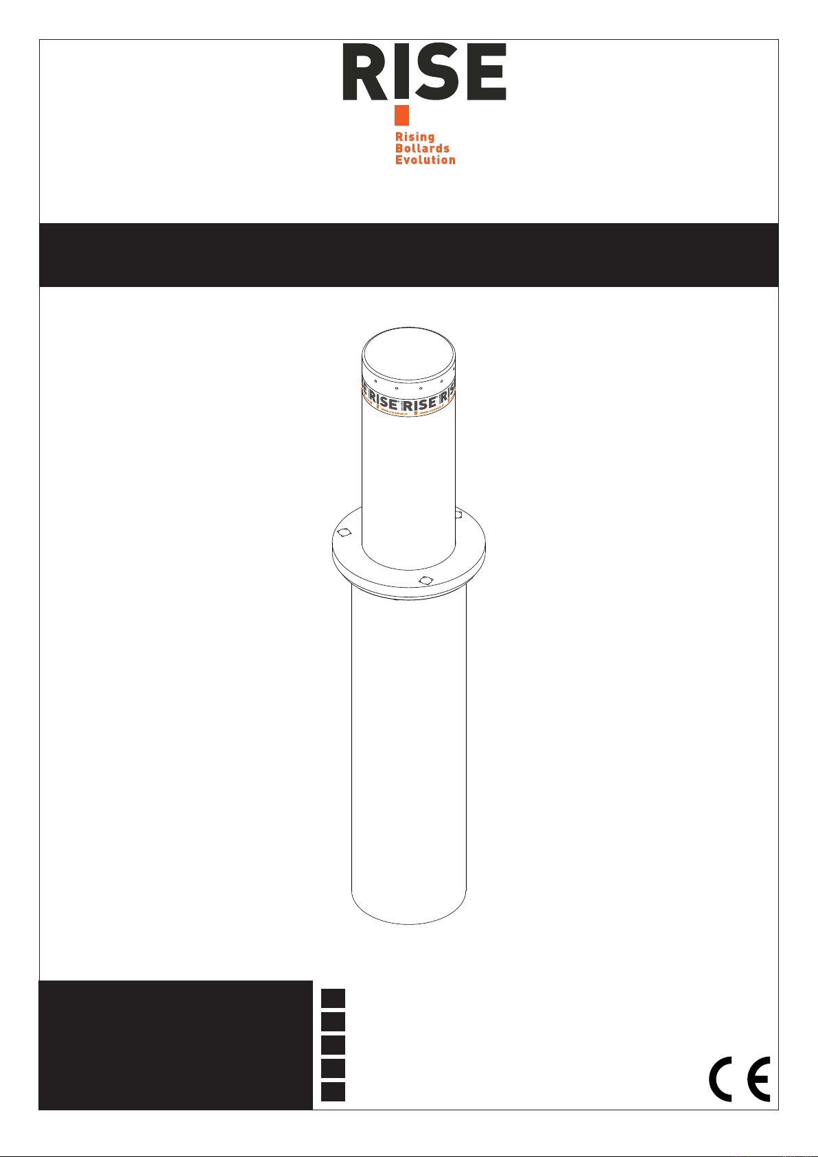
1 - Posizionare in verticale i tre elementi laterali come da immagine a lato.
2 - Usando le viti a testa bombata in dotazione si componga la struttura
esagonale. È molto importante assemblare i tre elementi in maniera verti-
cale e su una supercie che assicuri ottima planarità in modo da ottenere
un piano d'appoggio della angia di chiusura afdabile. Attenzione: La
testa della vite deve essere posizionata sul lato interno della cassa di
fondazione. Vedi gura a lato.
3 - Prima di ssare la angia superiore, inserire la protezione metallica
del tubo corrugato da diametro 40 mm che deve essere predisposto sul
terreno per il successivo collegamento elettrico alla centrale di comando.
Vedi gure a lato.

4 - VIGILANT - rev.00
VIGILANT - rev.00 - 5
I
Istruzioni di montaggio - VIGILANT 500
4 - Fissare la angia superiore con le viti a testa bombata in dotazione.
Attenzione: La testa delle viti deve essere posizionata sulla parte alta
della angia (interno cassa).
In questo modo la cassa di fondazione viene completata. Vedi gura a
lato.
5 - Fare lo scavo nel terreno con le quote indicate nell'immagine a lato
e preparare un fondo drenante adeguato. Inserire la cassa di fondazione
all'interno dello scavo. Attenzione: La cassa deve poggiare sul fondo
dello scavo e deve essere perfettamente verticale - controllare usan-
do una livella appoggiata sulla angia superiore.
Inserire la guaina corrugata di diametro 40 mm nella cassa attraverso la
guida metallica. Fissare la cassa con il cemento.
6 - Montare le zanche come in gura bloccandole in posizione con la ron-
della e la vite M10 a testa esagonale. Piegarle in base alla fondazione.
Attenzione: Assicurarsi, durante la colata, che il tassello di ssag-
gio posto al di sotto della zanca sia completamente sommerso dal
cemento. Usando una livella vericare l'orizzontalità del piano della
angia.
800 800
300/400
Cemento
Foro 800x800x1000 mm con fondo drenante
Guaina
corrugata
300
Sabbia
Fine
300
Ghiaia

6 - VIGILANT - rev.00
VIGILANT - rev.00 - 7
IIstruzioni di montaggio - VIGILANT 500
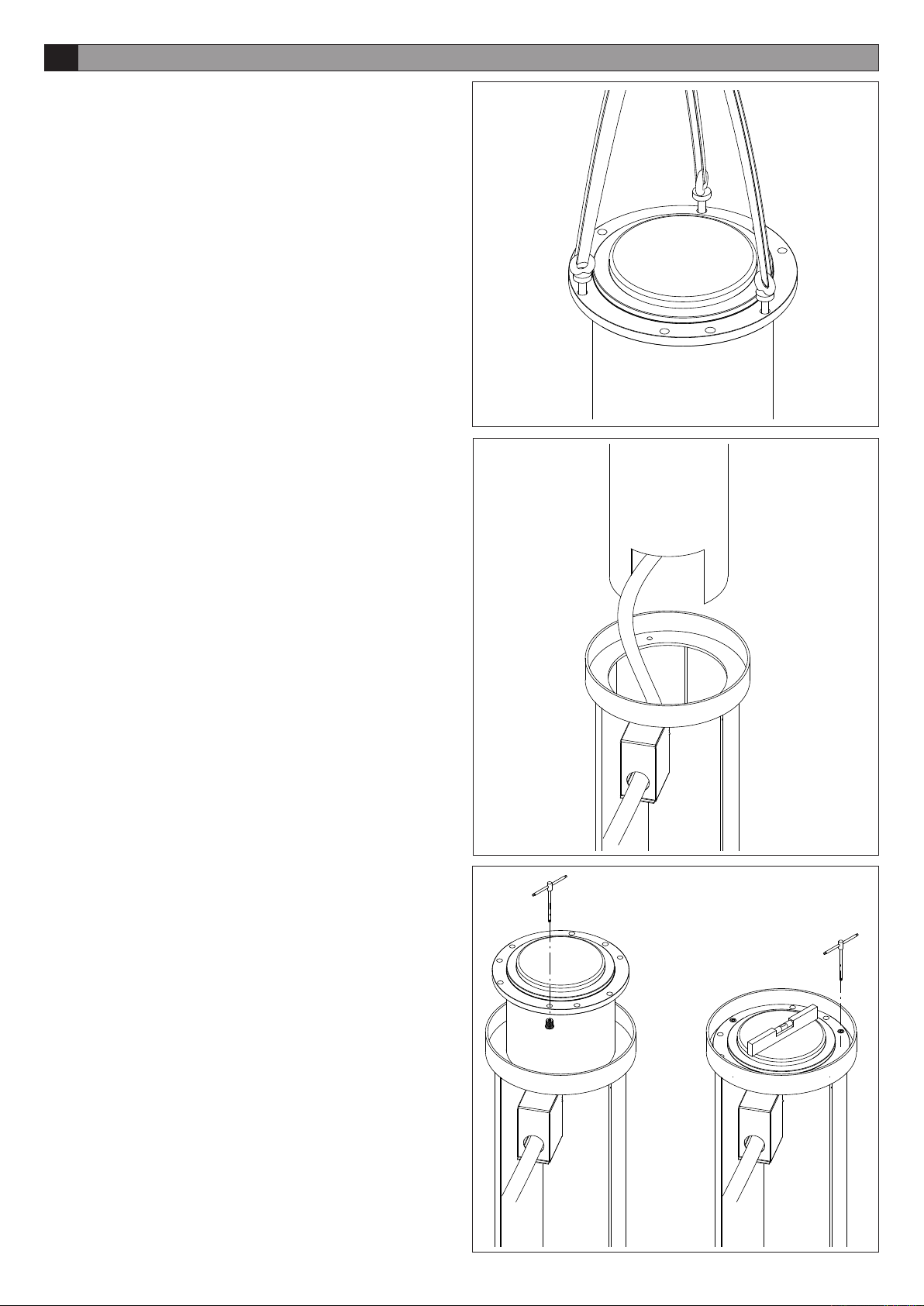
9 - Una volta posizionato il dissuasore all'interno della cassa, togliere i
golfari di sollevamento. Tramite i grani regolare la planarità del dissuasore
in riferimento al pavimento con una livella. Vedi gura a lato.
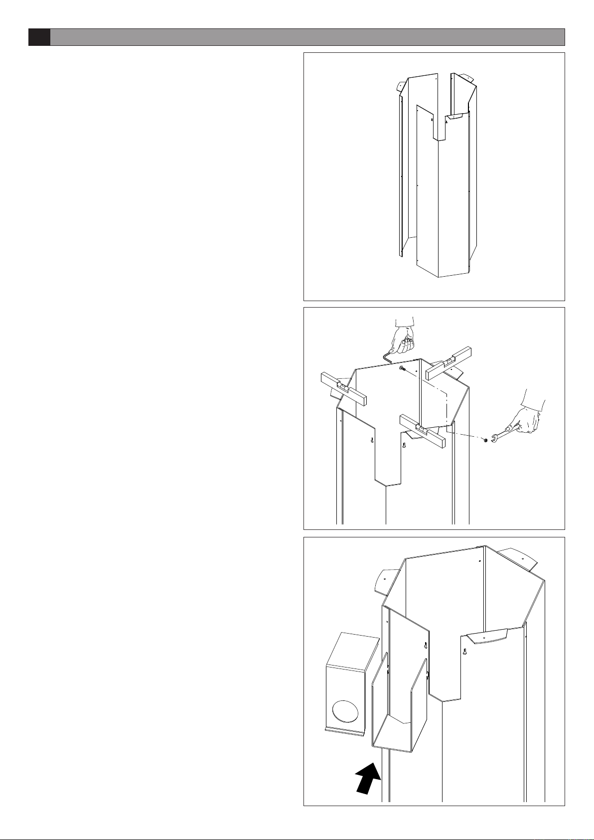
8 - Inserire il cavo elettrico nella guaina corrugata e poi, accompagnandone
la corsa, far scendere il dissuasore nella cassa di fondazione. Fare atten-
zione al cavo elettrico che deve essere libero nella sede della cassa e privo
di schiacciamenti. Vedi gure a lato.
7 - Utilizzare tre golfari con prigionieri M16 per sollevare il dissuasore.
Vedi gure a lato.

6 - VIGILANT - rev.00
VIGILANT - rev.00 - 7
I
Istruzioni di montaggio - VIGILANT 500
10 - Controllare con la angia calpestabile il livello nale dal pavimento
esterno. Eventualmente, tramite i grani da M16 inox, alzare il livello e curar-
ne la planarità. Inserire le rondelle e le viti M10 a testa esagonale. Coprire
i fori con i tappi in gomma in dotazione. Procedere con il collegamento
elettrico seguendo accuratamente lo schema fornito con la centrale. Vedi
gure a lato.
I
Dimensioni d'ingombro - Lista ricambi - VIGILANT 500
Ø 244.5
Ø 200
Ø 327
500923
Motore
Cod. 9687003
Banda catarifrangente
Cod. 9687002
Scheda elettronica
Cod. 9687001
ATTENZIONE - PERICOLO
MAI AZIONARE IL DISSUASORE PRIMA DI AVER FIS-
SATO LA FLANGIA CALPESTABILE!

8 - VIGILANT - rev.00
VIGILANT - rev.00 - 9
IIstruzioni per l'utilizzatore - VIGILANT 500
NORME DI SICUREZZA
- Non sostare nella zona di movimento del dissuasore.
- Non lasciare che i bambini giochino con i comandi o in prossimità del dissuasore.
- In caso di anomalie di funzionamento non tentare di riparare il guasto ma avvertire un tecnico specializzato.
MANOVRA MANUALE DI EMERGENZA
In caso di assenza di alimentazione di rete o di funzionamento anomalo, è possibile sbloccare il dissuasore tramite l'interruttore
d'emergenza posto vicino alla centrale. Tener premuto l'interruttore per far scendere il dissuasore.
MANUTENZIONE
- Sostituire massimo ogni 2 anni la batteria tampone nella centrale.
- Astenersi assolutamente dal tentativo di effettuare riparazioni: potreste incorrere in incidenti; per queste operazioni contattare
un tecnico specializzato.
- Il dissuasore non richiede manutenzioni ordinarie.
SMALTIMENTO
Qualora il dissuasore venga posto fuori servizio, è necessario seguire le disposizioni legislative in vigore al momento per quanto
riguarda lo smaltimento differenziato ed il riciclaggio dei vari componenti (metalli, plastiche, cavi elettrici, ecc.); è consigliabile
contattare il vostro installatore o una ditta specializzata ed abilitata allo scopo.
ATTENZIONE
Tutti i prodotti RISE sono coperti da polizza assicurativa che risponde di eventuali danni a cose o persone causati da difetti di
fabbricazione.

8 - VIGILANT - rev.00
VIGILANT - rev.00 - 9
I
VIGILANT 500

10 - VIGILANT - rev.00
VIGILANT - rev.00 - 11
The undersigned Mr. Paolo Peruzzo, legal representative of the company Rise S.r.l. - Via del Capitello, 42 - 36042 Marano
Vicentino (VI) – in the capacity of manufacturer declares that the product:
VIGILANT 500
complies in all its components with Directives:
- EMC Directive 2004/108/EC
- Low Voltage Directive 2006/95/EC
and with Technical Standards: EN 124:1995
as per checks carried out by: ECO Certicazioni S.p.A., via Mengolina, 33 - 48018 Faenza (RA)
Notied Body no. 0714
Marano Vicentino, 15/03/2009.
The legal representative
GB Declaration of conformity

10 - VIGILANT - rev.00
VIGILANT - rev.00 - 11
GB
General information and technical specications
We thank you for having chosen one of our Vigilant model automatic rising bollards.
All articles in the Rise range are the fruit of long experience in the sector of mechanical and electronic automations.
This is why today we are able to offer extremely reliable automatic rising bollards that, thanks to their performance, efciency
and durability, fully satisfy the nal customer’s requirements.
All our products are covered by a two-year warranty.
Furthermore, a product Civil Liability policy stipulated with a leading insurance company covers any damage to things or
persons caused by manufacturing defects.
General information
The Vigilant 500 automatic rising bollard, with its high resistance to impact and elegant design, is suitable for installation in
public or commercial areas and is particularly indicated for protecting buildings.
The standard version, manufactured in steel, is painted with cataphoresis-acrylic paints, a corrosion-proof treatment that
guarantees an extremely elevated resistance to the elements and to salty environments.
The bollard is operated with 24Vdc; an amperometric sensor detects any obstacles when rising and inverts the movement
immediately. The bollard is tted with 12 leds that operate in sequence and with a high-visibility reecting band. The bollard
can be easily unlocked in an emergency. In the event of a power cut different functions can be selected: the bollard can
remain in raised position or can be unlocked and lowered by keeping the emergency button pressed; automatic lowering in
the event of a power cut is also available (accessory). The system can also be tted with an uninterrupted power supply unit
(accessory) that allows the bollard to be used in automatic mode even in the event of a power cut.
The foundation case is manufactured in cataphoresis-painted steel and can easily be assembled on site before installation.
If the bollard is not installed immediately, a cover for closing the hole is available.
TECHNICAL DATA
MODEL
Power supply 230 Va.c. 10% 50 Hz
Motor power supply 24 Vdc
Motor power 90 W
Use Intensive use
Motor absorption (24 Vdc) 6 A
Protection level IP 68
Working temperature -20 C / +70 C
Lubrication
Cylinder dimensions
Permanent grease
Diameter 200x500 mm - thickness 8 mm
Foundation case dimensions Diameter 330x954 mm
Impact resistance 11.000 J (without permanent deformation)
Breaking strength
Rising time
180.000 J
4"
Lowering time 2.5"
VIGILANT 500
Weight 75 kg
Finish Black cataphoresis
12 - VIGILANT - rev.00
VIGILANT - rev.00 - 13
GB Assembly instructions - VIGILANT 500
1 - Place the three side elements vertically as in the image alongside.
2 - Using the round head screws provided, assemble the hexagonal struc-
ture. It is very important to assemble the three elements vertically and on
a surface that ensures excellent atness so as to obtain a reliable support
surface for the closing ange. Attention: The screw head must be placed
on the internal side of the foundation case. See gure alongside.
3 - Before xing the upper ange, insert the metallic protection of the 40 mm
diameter corrugated pipe which must be set in the ground to make the sub-
sequent electrical connection with the control unit. See gures alongside.

12 - VIGILANT - rev.00
VIGILANT - rev.00 - 13
GB
Assembly instructions - VIGILANT 500
4 - Fix the upper ange using the round head screws provided.
Attention: The screw heads must be placed on the upper part of the
ange (inside the case).
This way the foundation case is complete. See gure alongside.
5 - Carry out the excavation in the ground with the measurements indicated
in the image alongside and prepare a suitable draining foundation. Insert
the foundation case in the excavation.
Attention: The case must rest on the bottom of the excavation and
must be perfectly vertical - check this by placing a spirit level on the
upper ange.
Insert the 40 mm diameter corrugated sheath in the case using the metal
guide. Fix the case with cement.
6 - Fit the clamps as in the gure locking them in position with the washer
and the M10 hexagonal head screw. Fold them according to the foundation.
Attention: Make sure, during the cast, that the xing plug you nd un-
der the cramp-iron is completely covered with concrete. Using a spirit
level, check if the ange plane is horizontal.
800 800
300/400
Cement
Hole 800x800x1000 mm with draining foundation
Corrugated
sheath
300
Fine
sand
300
Gravel
14 - VIGILANT - rev.00
VIGILANT - rev.00 - 15
GB Assembly instructions - VIGILANT 500
9 - After positioning the bollard inside the case, remove the lifting eyebolts.
Using the dowels, adjust the level positioning of the bollard with respect to
the oor, checking it with a spirit level. See gure alongside.
8 - Insert the electrical cable in the corrugated sheath and then, guiding it,
lower the bollard into the foundation case. Pay attention to the electrical
cable that must be free in the case housing without being crushed. See
gures alongside.
7 - Use three eyebolts with M16 studs to lift the bollard.
See gures alongside.

14 - VIGILANT - rev.00
VIGILANT - rev.00 - 15
GB
Assembly instructions - VIGILANT 500
10 - With the treadable ange check the nal level with respect to the ex-
ternal oor. If required, using the M16 stainless steel dowels, raise the level
and adjust the level positioning. Insert the washers and the M10 hexagonal
head screws. Cover the holes with the rubber caps provided. Carry out the
electrical connection carefully following the diagram supplied with the control
unit. See gures alongside.
GB
Overall dimensions - Spare parts list - VIGILANT 500
Ø 244.5
Ø 200
Ø 327
500923
Motor
Code 9687003
Reecting band
Code 9687002
Electronic board
Code 9687001
ATTENTION - DANGER
NEVER ACTIVATE THE RISING BOLLARD
BEFORE HAVING FIXED THE TREADABLE
FLANGE!

16 - VIGILANT - rev.00
VIGILANT - rev.00 - 17
GB User instructions - VIGILANT 500
SAFETY REGULATIONS
- Do not stand within the area of movement of the rising bollard.
- Do not allow children to play with the controls, or in the vicinity of the rising bollard.
- In case of malfunctions do not attempt to repair the fault but call a specialised technician.
EMERGENCY MANUAL OPERATION
In the event of a power cut or of malfunction the bollard can be unlocked with the emergency switch tted close to the control
unit. Keep the switch pressed to lower the bollard.
MAINTENANCE
- Replace the buffer battery in the control unit maximum every 2 years.
- Absolutely avoid attempting to carry out repairs: you could cause accidents; for such operations call a specialised techni-
cian.
- The bollard does not require routine maintenance.
DISPOSAL
If the bollard is withdrawn from service, the current laws and regulations in force concerning the separate waste disposal and
the recycling of the various components (metals, plastics, electric cables etc.) must be respected; it is advisable to contact
your installer or a specialised company, authorised for the purpose.
ATTENTION
All RISE products are covered by an insurance policy that answers for any damage to things or persons caused by manu-
facturing defects.

16 - VIGILANT - rev.00
VIGILANT - rev.00 - 17
GB
VIGILANT 500

18 - VIGILANT - rev.00
VIGILANT - rev.00 - 19
Der Unterzeichnende, Paolo Peruzzo, gesetzlicher Vertreter der Firma Rise S.r.l. - Via del Capitello, 42 - 36042 Marano
Vicentino (VI) – in ihrer Eigenschaft als Hersteller, erklärt, dass das Produkt:
VIGILANT 500
in all seinen Teilen konform ist mit den Richtlinien
- Richtlinie EMC 2004/108/EG
- Niederspannungsrichtlinie 2006/95/EG
und mit den Technischen Normen: EN 124:1995
wie aus den Prüfungen hervorgeht, die durchgeführt wurden von: ECO Certicazioni S.p.A., Via Mengolina, 33 - 48018
Faenza (RA)
Benannte Stelle Nr. 0714
Marano Vicentino, den 15.03.2009.
Der gesetzliche Vertreter
DKonformitätserklärung

18 - VIGILANT - rev.00
VIGILANT - rev.00 - 19
D
Allgemeine Informationen und technische Spezikationen
Wir freuen uns, dass Sie sich für eines unserer Modelle der automatisch versenkbaren Poller Vigilant entschieden haben.
Alle Artikel der Angebotspalette Rise sind das Ergebnis einer langjährigen Erfahrung auf dem Gebiet der mechanischen
und elektronischen Torantriebe.
Eben aus diesem Grund sind wir heute in der Lage, extrem zuverlässige Poller anzubieten, welche dank ihrer Leistungsfähigkeit,
Efzienz und Haltbarkeit alle Anforderungen des Endkunden voll erfüllen.
Alle unsere Produkte verfügen über eine Garantie von zwei Jahren.
Daneben deckt eine mit einer führenden Versicherungsgesellschaft abgeschlossene Produkthaftpichtversicherung eventuelle
Sach- oder Personenschäden, die auf Fabrikationsfehler zurückzuführen sind.
Allgemeine Angaben
Der automatische Poller Vigilant 500 eignet sich dank seiner hohen Stoßfestigkeit und dem eleganten Design für die Installation
an öffentlichen oder kommerziellen Orten und ist besonders zum Schutz von Wohngebäuden angezeigt.
Die Standardausführung aus Stahl hat eine Kataphorese-Lackierung mit Acryllacken, eine Korrosionsschutzbehandlung,
welche hohe Beständigkeit gegen Witterungseinüsse und salzige Atmosphären verleiht.
Der Poller funktioniert mit 24Vdc; ein amperometrischer Sensor erkennt etwaige Hindernisse während des Ausfahrens
und kehrt die Bewegung umgehend um. Der Poller ist mit 12 LEDs mit sequentieller Funktion und einem gut sichtbaren
reektierenden Streifen ausgestattet. In Notfällen kann der Poller schnell entriegelt werden. Bei Stromausfällen können
verschiedene Funktionen selektiert werden: der Poller kann ausgefahren bleiben, oder entriegelt und eingefahren werden,
indem die Notfalltaste gedrückt gehalten wird; daneben steht als Option auch das automatische Einfahren bei Stromausfall
zur Verfügung. Das System ist außerdem für die Installation einer unterbrechungsfreien Stromversorgung (Option) vorbereitet,
welche auch bei Stromausfall den Einsatz des Pollers im Automatikmodus erlaubt.
Der Fundamentkasten besteht aus Stahl mit Kataphorese-Lackierung und kann vor der Installation problemlos vor Ort zusam-
mengebaut werden. Falls der Poller nicht sofort installiert wird, kann der Schacht mit einem Deckel verschlossen werden.
TECHNISCHE DATEN
MODELL
Versorgung 230 Va.c. 10% 50 Hz
Motorspeisung 24 Vdc
Motorleistung 90 W
Gebrauch Intensiver Einsatz
Motorstromaufnahme (24 Vdc) 6 A
Schutzgrad IP 68
Betriebstemperatur -20 C / +70 C
Schmierung
Zylindergröße
Permanentfett
Durchmesser 200x500 mm - Stärke 8 mm
Größe des Fundamentkastens Durchmesser 330x954 mm
Stoßfestigkeit 11.000 J (ohne bleibende Verformung)
Bruchfestigkeit
Ausfahrzeit
180.000 J
4"
Einfahrzeit 2.5"
VIGILANT 500
Gewicht 75 kg
Fertigung Schwarze Kataphorese

20 - VIGILANT - rev.00
VIGILANT - rev.00 - 21
DMontageanleitung - VIGILANT 500
1 - Die drei Seitenelemente senkrecht aufstellen, wie in der seitlichen
Abbildung gezeigt.
2 - Mit Hilfe der mitgelieferten Linsensenkschrauben die hexagonale Struktur
zusammenbauen. Die drei Elemente müssen unbedingt vertikal und auf
einer vollkommen ebenen Oberäche zusammengebaut werden, damit eine
zuverlässige Auage für den Verschlussansch erhalten wird.
Achtung: Der Schraubenkopf muss an der Innenseite des Fundament-
kastens positioniert werden. Siehe seitliche Abbildung.
3 - Bevor der obere Flansch befestigt wird, die Schutzverkleidung aus
Metall des Wellrohrs mit Durchmesser 40 mm anbringen, welches für den
elektrischen Anschluss an die Steuerzentrale am Boden vorbereitet sein
muss. Siehe seitliche Abbildungen.
Table of contents
Languages:
Other Rise Control System manuals


Popular Control System manuals by other brands


Roger
Roger H85/TDR Instruction and warnings for the installer

Balboa
Balboa MLM990S Quick reference guide

Altronic
Altronic VariSpark CPU-XL operating instructions

Allen-Bradley
Allen-Bradley ControlLogix 1756-CNB user manual

Pilz
Pilz PSSu E F PS1 operating manual

Polyaire
Polyaire Zonemaster Unipoint Setup guide