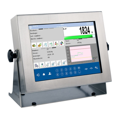
RADWAG PUE HY10 User manual

USER MANUAL
ITKU-88-03-08-17-EN
PUE HY10
WEIGHING INDICATOR
www.radwag.com

2
AUGUST 2017

3
Table OF CONTENTS
1. INTENDED USE .................................................................................................................................................9
2. PRECAUTIONARY MEASURES.......................................................................................................................9
2.1.Precautions...................................................................................................................................................9
2.2.Operation in a strong electrostatic field........................................................................................................9
2.3.Scale washing ............................................................................................................................................10
3. WARRANTY CONDITIONS .............................................................................................................................11
4. UNPACKING AND MOUNTING.......................................................................................................................12
5. WEIGHING INDICATOR STRUCTURE...........................................................................................................13
5.1.External view..............................................................................................................................................13
5.2.Main dimensions ........................................................................................................................................13
5.3.Description of connectors...........................................................................................................................14
5.4.Connectors’ pins layout..............................................................................................................................15
5.5.Inputs/Outputs............................................................................................................................................16
5.5.1. Inputs/Outputs: technical specifications.........................................................................................16
5.5.2. Inputs/Outputs schematic diagram.................................................................................................17
6. GETTING STARTED........................................................................................................................................17
7. KEYPAD OVERLAY.........................................................................................................................................17
8. FUNCTIONS OF KEYS....................................................................................................................................18
9. PROGRAM STRUCTURE................................................................................................................................19
10. INDICATING WINDOW..................................................................................................................................20
10.1. Top bar.....................................................................................................................................................20
10.2. Workspace ...............................................................................................................................................21
11. LOGGINGG IN................................................................................................................................................21
11.1. Logging in - procedure.............................................................................................................................21
11.2. Logging out procedure.............................................................................................................................22
11.3. Authorization access levels......................................................................................................................22
12. NAVIGATING WITHIN THE MENU ...............................................................................................................23
12.1. Keys .........................................................................................................................................................23
12.2. Return to weighing...................................................................................................................................25
13. WEIGHING .....................................................................................................................................................25
13.1. Conditions of operational use ..................................................................................................................25
13.2. Zeroing.....................................................................................................................................................26
13.3. Tarring......................................................................................................................................................27
13.4. Weighing for dual range scales ...............................................................................................................27
13.5. Toggling between weighing units.............................................................................................................28
14. SCALE PARAMETERS .................................................................................................................................29
14.1. Median filter..............................................................................................................................................29
14.2. Filter .........................................................................................................................................................30
14.3. Autozero...................................................................................................................................................30
14.4. Minimum weight for different functions (LO)............................................................................................31
14.5. Last digit...................................................................................................................................................31
15. COMMUNICATION ........................................................................................................................................32
15.1. RS 232 settings........................................................................................................................................32
15.2. ETHERNET setting..................................................................................................................................33
15.3. TCP protocol setting ................................................................................................................................33
15.4. Wi-Fi.........................................................................................................................................................34
15.4.1. Wi-Fi network status .....................................................................................................................34
15.4.2. Available networks........................................................................................................................34
15.4.3. Transmission parameters .............................................................................................................35
16. DEVICES........................................................................................................................................................36
16.1. Computer..................................................................................................................................................36
16.1.1. Computer port...............................................................................................................................36
16.1.2. Computer address ........................................................................................................................37
16.1.3. Continuous transmission...............................................................................................................37
16.1.4. Weighing printout template...........................................................................................................37
16.1.5. Cooperation with “E2R System” ...................................................................................................38
16.2. Printer.......................................................................................................................................................39
16.2.1.Printer port ....................................................................................................................................40
16.2.2. Printer code page..........................................................................................................................40
16.2.3. Templates for printouts.................................................................................................................40
16.3. Printouts activation...................................................................................................................................42

4
16.4. Barcode scanner......................................................................................................................................43
16.4.1. Port for barcode scanner ..............................................................................................................43
16.4.2. Prefix / Suffix.................................................................................................................................44
16.4.3. Field selection...............................................................................................................................44
16.4.4. Test ...............................................................................................................................................46
16.5. Transponder card reader .........................................................................................................................47
16.5.1. Com port for transponder card readers ........................................................................................47
16.5.2. Procedure of attributing the card number to an operator .............................................................48
16.6. Additional display.....................................................................................................................................48
16.6.1. Additional display port...................................................................................................................48
16.6.2. Communication protocol frame.....................................................................................................49
16.7. Modbus RTU............................................................................................................................................49
16.7.1. Communication port......................................................................................................................50
16.7.2. Address.........................................................................................................................................50
16.8. Advanced settings....................................................................................................................................50
17. DISPLAY ........................................................................................................................................................51
17.1. Display components.................................................................................................................................52
17.2. Mass.........................................................................................................................................................54
17.3. Text strings...............................................................................................................................................55
17.3.1. Display templates..........................................................................................................................55
17.4. Function keys...........................................................................................................................................57
17.5. Bargraph...................................................................................................................................................57
17.5.1. Bargraph type................................................................................................................................58
17.5.2. Bargraph “Fast weighing”..............................................................................................................58
17.5.3. Bargraph “Signalling of checkweighing ranges”...........................................................................59
17.5.4. Bargraph type: „Linear”.................................................................................................................60
17.5.5. “Control” bargraph.........................................................................................................................61
18. INPUTS / OUTPUTS ......................................................................................................................................63
18.1. Configuration of inputs.............................................................................................................................63
18.2. Configuration of outputs...........................................................................................................................64
19. AUTHORIZATION..........................................................................................................................................65
19.1. Anonymous Operator...............................................................................................................................65
19.2. Date and time...........................................................................................................................................66
19.3. Printouts...................................................................................................................................................66
19.4. Databases edition ....................................................................................................................................67
19.5. Delete older data......................................................................................................................................67
19.6. Set element from the database................................................................................................................68
19.7. PGC..........................................................................................................................................................69
20. UNITS .............................................................................................................................................................69
20.1. Units accessibility.....................................................................................................................................69
20.2. Start unit...................................................................................................................................................70
20.3. User defined units ....................................................................................................................................71
20.4. Acceleration of gravity..............................................................................................................................71
21. OTHER PARAMETERS.................................................................................................................................72
21.1. Languages ...............................................................................................................................................72
21.2. Setting date and time...............................................................................................................................72
21.3. Sound signal ............................................................................................................................................73
21.4. Screen brightness ....................................................................................................................................74
21.5. Energy saving mode ................................................................................................................................74
21.6. Screen timeout.........................................................................................................................................75
21.7. Log out automatically when time elapses................................................................................................75
21.8. Permissible quantity of unsuccessful logging..........................................................................................76
21.9. Logging in required ..................................................................................................................................76
21.10.Start logo ................................................................................................................................................76
21.11.Error information preview time ...............................................................................................................77
21.12.Export / import of settings.......................................................................................................................78
22. USER ADJUSTMENT ....................................................................................................................................78
22.1. Adjusting procedure.................................................................................................................................79
22.2. Start mass adjustment .............................................................................................................................80
22.3. Report from adjustment process..............................................................................................................81
22.4. Adjustment track record...........................................................................................................................82
23. SOFTWARE UPDATE ...................................................................................................................................82
23.1. ON-LINE updating....................................................................................................................................83
23.2. Update from pen drive .............................................................................................................................84
23.3. Changes in software ................................................................................................................................85


5
24. SPECIAL FUNCTIONS OF WORKING MODES...........................................................................................86
24.1. Working modes accessibility....................................................................................................................87
24.2. Save mode...............................................................................................................................................88
24.3. Down-weighing.........................................................................................................................................88
24.4. Checkweighing.........................................................................................................................................89
24.5. Tare mode................................................................................................................................................89
24.6. Labelling mode.........................................................................................................................................90
24.6.1. Setting of the number of labels to print.........................................................................................91
24.6.2. Setting of the number of cumulative labels to print ......................................................................91
24.6.3. Setting of the number of CC labels to print...................................................................................91
24.6.4. Automatic triggering of cumulative labels.....................................................................................92
24.6.5. Automatic triggering cumulative labels of cumulative labels........................................................93
24.7. Statistics...................................................................................................................................................95
24.8. Differential weighing.................................................................................................................................95
24.8.1. Local settings ................................................................................................................................96
24.8.2. Reporting completed processes of differential weighing..............................................................96
24.9. Peak hold .................................................................................................................................................97
24.10.Information about saved measurement..................................................................................................98
24.11.Packaging quantity query.......................................................................................................................98
25. WORKING MODE - WEIGHING....................................................................................................................99
25.1. Starting the working mode.......................................................................................................................99
25.2. Local setting of a working mode ..............................................................................................................99
26. WORKING MODES – PARTS COUNTING.................................................................................................100
26.1. Starting the working mode.....................................................................................................................100
26.2. Local settings of the working mode .......................................................................................................100
26.2.1. Automatic correction of reference mass.....................................................................................101
26.2.2. Minimum reference mass............................................................................................................102
26.3. Setting a reference unit by entering known piece mass........................................................................103
26.4. Setting a reference unit by weighing a sample......................................................................................103
26.5. Setting the reference mass by entering single piece mass directly to the database............................104
26.6. Entering the unit mass to the database.................................................................................................104
27. WORKING MODES – PERCENT SETUP (DEVIATIONS) .........................................................................105
27.1. Starting the operating mode...................................................................................................................105
27.2. Local settings of the working mode .......................................................................................................105
27.3. Reference unit mass estimated by weighment......................................................................................106
27.4. Entering reference unit mass into the memory......................................................................................106
28. WORKING MODES - DOSING....................................................................................................................107
28.1. Starting the working mode.....................................................................................................................107
28.2. Dosing process structure .......................................................................................................................108
28.3. Local setting of a working mode ............................................................................................................108
28.4. Description of functions and setting dosing process .............................................................................109
28.5. Creating a new dosing process .............................................................................................................112
28.6. Instances of dosing processes ..............................................................................................................113
28.6.1. Instance 1 – Manual dosing process of 4 ingredients on 2 weighing platforms.........................113
28.6.2. Instance 2 – Automatic dosing of 2 ingredients on 2 weighing platforms..................................115
28.6.3. Instance 3 – Mixed dosing process ............................................................................................117
28.7. Reporting of completed dosing processes ............................................................................................120
29. WORKING MODES – FORMULATION.......................................................................................................121
29.1. Starting the working mode.....................................................................................................................121
29.2. Local setting of a working mode ............................................................................................................122
29.3. Creating a new formulation....................................................................................................................123
29.4. Formula making process........................................................................................................................126
29.5. Reporting from completed formula making processes..........................................................................128
30. WORKING MODE – PGC (CONTROL OF PREPACKED GOODS) ..........................................................129
30.1. Starting the working mode.....................................................................................................................130
30.2. Control settings mode window...............................................................................................................131
30.3. Local setting of a working mode ............................................................................................................132
30.4. Editing a product to be controlled ..........................................................................................................133
30.5. Control start procedure ..........................................................................................................................135
30.6. Control aborting procedure....................................................................................................................136
30.7. Logging out from a control process in progress ....................................................................................137
30.8. Non-destructive average tare control mode ..........................................................................................138
30.9. Performing non-distructive testing in mode Empty-Full.........................................................................144
30.10.Performing destructive testing in modes Empty-Full and Full-Empty..................................................145
30.11.Control in accordance with internal criteria ..........................................................................................146

6
30.11.1. Abort of control - procedure......................................................................................................148
30.11.2. Procedure of control completion...............................................................................................149
30.12.Simultaneous carrying out two control processes................................................................................150
30.13.Report from estimating average tare....................................................................................................151
30.14.Report from product testing..................................................................................................................153
31. WORKING MODES – DENSITY..................................................................................................................155
31.1. Starting the working mode.....................................................................................................................155
31.2. Local setting of a working mode ............................................................................................................155
31.3. Carrying out density determination procedure.......................................................................................156
31.3.1. Determining density of liquids.....................................................................................................156
31.3.2. Determining density of solids......................................................................................................158
31.3.3. Determining density of pycnometer............................................................................................159
31.3.4. Determining density of a porous body........................................................................................161
31.4. Reporting from completed density determination processes ................................................................163
31.5. Table of density parameter for water.....................................................................................................164
31.6. Table of density parameter for ethyl alcohol..........................................................................................164
32. WORKING MODES – ANIMAL WEIGHING................................................................................................165
32.1. Starting the operating mode...................................................................................................................165
32.2. Local setting of a working mode ............................................................................................................165
32.3. Carrying out animals weighing procedure .............................................................................................166
33. WORKING MODE – VEHICLE SCALE.......................................................................................................166
33.1. Working mode activating procedure......................................................................................................166
33.2. Working mode local settings..................................................................................................................168
33.3. Vehicle transaction course.....................................................................................................................168
33.3.1.Entrance / Exit transaction..........................................................................................................168
33.3.2. Control weighment transaction ...................................................................................................172
33.4. Open transactions table.........................................................................................................................174
33.5. Printout templates for an ongoing transaction.......................................................................................175
33.6. Executed transactions – reporting .........................................................................................................176
34. DATABASES................................................................................................................................................177
34.1. Database configuration..........................................................................................................................178
34.1.1. Databases accessibility...............................................................................................................178
34.1.2. Categories...................................................................................................................................178
34.1.3. Database variables operation.....................................................................................................179
34.1.4. Change name of an extra variables database............................................................................180
34.1.5. Change database records preview.............................................................................................180
34.1.6. Databases export / import...........................................................................................................181
34.2. Searching databases .............................................................................................................................181
34.2.1. Quick name search.....................................................................................................................182
34.2.2. Quick code search ......................................................................................................................182
34.3. Adding new items in databases.............................................................................................................182
34.4. Deleting items in databases...................................................................................................................183
34.5. Printing items from databases ...............................................................................................................183
34.6. Context menu.........................................................................................................................................184
34.7. Database edit window............................................................................................................................185
34.7.1. Operators’ database ...................................................................................................................185
34.7.2. Database of products..................................................................................................................185
34.7.3. Database of clients .....................................................................................................................187
34.7.4. Database of dosing processes ...................................................................................................188
34.7.5. Database of formulations............................................................................................................189
34.7.6. PGC time schedules database...................................................................................................189
34.7.7. Database of vehicles...................................................................................................................190
34.7.8. Identification processes database ..............................................................................................190
34.7.9. Database of packages................................................................................................................191
34.7.10. Database of warehouses..........................................................................................................191
34.7.11. Database of labels....................................................................................................................192
34.7.12. Database of universal variables ...............................................................................................193
34.7.13. Extra variables database..........................................................................................................193
34.7.14. Images database ......................................................................................................................194
35. REPORTS.....................................................................................................................................................195
35.1. Reports configuration.............................................................................................................................195
35.1.1. Reports accessibility ...................................................................................................................196
35.1.2. Configuration of a lot number .....................................................................................................196
35.1.3. Configuration of a batch number ................................................................................................196
35.1.4. Query for number of weighings to be deleted.............................................................................197

7
35.2. Deleting older data.................................................................................................................................198
35.3. Weighment date search.........................................................................................................................198
35.4. Reports from weighment records...........................................................................................................199
35.4.1. Filtering........................................................................................................................................199
35.4.2. Report printout ............................................................................................................................200
35.4.3. Weighments chart.......................................................................................................................201
35.4.4. Export a database to a file..........................................................................................................202
35.4.5. Counter of weighments records..................................................................................................204
35.5. Reports preview.....................................................................................................................................205
35.5.1. Weighments / Alibi ......................................................................................................................205
35.5.2. Reports from dosing....................................................................................................................206
35.5.3. Reports from recipes...................................................................................................................207
35.5.4. Density reports............................................................................................................................208
35.5.5. Controls reports...........................................................................................................................209
35.5.6. Average tare reports...................................................................................................................210
35.5.7. Report from vehicle scale ...........................................................................................................212
35.5.8. Differential weighments reports ..................................................................................................212
36. IDENTIFICATION PROCESSES .................................................................................................................213
36.1. Identification process – creation ............................................................................................................214
36.2. List of identification process functions ...................................................................................................215
36.3. Identification process – activation procedure ........................................................................................217
36.3.1. Activation by programmable button............................................................................................217
36.3.2. Activation by operator logging ....................................................................................................218
36.3.3. Activation by product selection ...................................................................................................218
36.3.4. Example of process forming and its realization..........................................................................219
37. COMMUNICATION PROTOCOL.................................................................................................................222
37.1. General information................................................................................................................................222
37.2. List of RS commands.............................................................................................................................223
37.3. Respond message format......................................................................................................................224
37.4. Command’s description .........................................................................................................................224
37.4.1. Zeroing........................................................................................................................................224
37.4.2. Tarring.........................................................................................................................................225
37.4.3. Get tare value..............................................................................................................................225
37.4.4. Set tare value..............................................................................................................................225
37.4.5. Send the stable result in basic unit.............................................................................................226
37.4.6. Send the result immediately in basic unit ...................................................................................226
37.4.7. Send immediate results from all platforms in basic units ...........................................................227
37.4.8. Send the stable result in current unit..........................................................................................227
37.4.9. Send the result immediately in current unit ................................................................................228
37.4.10. Switch on continuous transmission in basic unit......................................................................229
37.4.11. Switch off continuous transmission in basic unit......................................................................229
37.4.12. Switch on continuous transmission in current unit...................................................................229
37.4.13. Switch off continuous transmission in current unit ...................................................................230
37.4.14. Set lower threshold...................................................................................................................230
37.4.15. Set upper threshold ..................................................................................................................230
37.4.16. Read lower threshold................................................................................................................230
37.4.17. Read upper threshold ...............................................................................................................231
37.4.18. Simulation of pressing ENTER/PRINT key ..............................................................................231
37.4.19. Change platform .......................................................................................................................231
37.4.20. Give balance serial number......................................................................................................232
37.4.21. Set mass value of a single item................................................................................................232
37.4.22. Set reference mass value.........................................................................................................232
37.4.23. Activate sound signal................................................................................................................233
37.4.24. Give available working modes..................................................................................................233
37.4.25. Set working mode.....................................................................................................................234
37.4.26. Give current working mode.......................................................................................................235
37.4.27. Send all implemented commands ............................................................................................235
37.5. Manual printouts / automatic printouts...................................................................................................236
38. MODBUS RTU COMMUNICATION PROTOCOL.......................................................................................236
38.1. Memory map..........................................................................................................................................238
38.1.1. Output address............................................................................................................................238
38.1.2. Input address ..............................................................................................................................239
38.2. Description of variables..........................................................................................................................239
38.2.1. Output variables..........................................................................................................................239
38.2.2. Input variables.............................................................................................................................243

8
39. COOPERATION WITH PERIPHERAL DEVICES.......................................................................................246
40. OPTIONAL EXTENSIONS MODULES........................................................................................................247
40.1. Additional I/O module.............................................................................................................................247
40.1.1. 12IN/12OUT module: technical specifications............................................................................247
40.1.2. 12IN/OUT schematic diagrams...................................................................................................248
40.1.3. Inputs/Outputs signals overview.................................................................................................249
40.2. 4IN/4OUT – 4IN .....................................................................................................................................249
40.2.1. 4IN/4OUT module: technical specifications................................................................................249
40.2.2. 4IN/4OUT schematic diagram ....................................................................................................250
40.2.3. Inputs/Outputs signals overview.................................................................................................250
40.3. Analog outputs module ..........................................................................................................................251
40.3.1. AN module setup ........................................................................................................................251
40.3.2. AN module: technical specifications...........................................................................................252
40.3.3. Wiring diagrams for the AN module............................................................................................252
40.4. Module for an additional platform – DP4...............................................................................................253
40.4.1. DP4 module: technical specifications.........................................................................................253
40.4.2. Colours of weighing platform signal wires..................................................................................253
40.5. RS485 module (309Rxxxx)....................................................................................................................254
40.6. PROFIBUS board...................................................................................................................................255
40.7. Additional modules positioning ..............................................................................................................256
40.7.1. Exclusions for additional modules installation............................................................................256
41. PROFIBUS COMMUNICATION MODULE..................................................................................................257
41.1. Socket topology......................................................................................................................................257
41.2. Memory map..........................................................................................................................................258
41.2.1. Output address............................................................................................................................258
41.2.2. Input address ..............................................................................................................................259
41.3. Description of variables..........................................................................................................................260
41.3.1. Output variables..........................................................................................................................260
41.4. Input variables........................................................................................................................................263
42. DIAGRAMS OF CONNECTION CABLES...................................................................................................267
43. ADDITIONAL EQUIPMENT.........................................................................................................................269
44. TECHNICAL PARAMETERS.......................................................................................................................270
45. ERROR MESSAGES ...................................................................................................................................271
46. APPENDIX 01 – Variables for printouts....................................................................................................272
46.1. Inventory of variables.............................................................................................................................272
46.2. Formatting variables...............................................................................................................................280
46.3. Mathematical function............................................................................................................................282
47. APPENDIX 02 – Functions of programmable buttons............................................................................284
48. APPENDIX 03 – Label template.................................................................................................................290
48.1. Designing a label from the indicator level..............................................................................................290
48.2. Designing a label on a computer...........................................................................................................291
48.3. Saving label templates in the scale .......................................................................................................295
48.4. Attributing a label to a product...............................................................................................................295
48.5. Attributing a label to a client...................................................................................................................296
48.6. Printing labels.........................................................................................................................................296
49. APPENDIX 04 - CITIZEN printer setting....................................................................................................296
50. APPENDIX 05 - ZEBRA printer setting .....................................................................................................297
51. APPENDIX 06 - Communication with barcode scanners .......................................................................297
52. APPENDIX 07 – Computer Program „ViewerKTP”..................................................................................298
53. APPENDIX 08 – Cooperation with HRP Weighing Platform...................................................................300
53.1. External ambient conditions...................................................................................................................300
53.2. LO Threshold for automatic functions....................................................................................................301
53.3. Automatic adjustment ............................................................................................................................301
53.4. Internal adjustment.................................................................................................................................303
53.5. Automatic adjustment time-triggered.....................................................................................................304

9
1. INTENDED USE
PUE HY10 weighing indicator is designed to be a component of industrial
scales operation of which is based on load cells. It features stainless steel
housing with IP 68/69, with thus high IP rate it can be operated within wide
temperature range: -10oC – 40oC and wherever high humidity prevails.
Colour capacitive 10,1” display with touchscreen allows intuitive operation,
no keyboard is needed.
Weighing indicator of standard line is equipped with 2 x USB, 1 x RS232,
1 x Ethernet and 1 x 4IN/4OUT connectors. The device allows three additional
weighing modules coupling. It can cooperate with barcode scanners, receipt
printers, labellers, RFID readers and PC equipment (mouse, keyboard USB
flash memory).
2. PRECAUTIONARY MEASURES
2.1. Precautions
A. Please, read carefully this user manual before and use the device
according to its intended use;
B. Weighed loads should be placed in possibly central part of scale pan;
C. Do not clean the device with agents causing corrosion;
D. Weighing pan should be loaded with goods having gross mass lower
than maximal capacity of the scale;
E. Do not leave loads on the pan for longer period of time ;
F. In case of failure, immediately disconnect scale power supply;
G. Devices that are to be withdrawn from usage should be utilized
according to the law.
2.2. Operation in a strong electrostatic field
If the device is about to operate in a strong electrostatic field (e.g. printing
houses etc.) it should be connected to the earthing. Connect it to the
clamp terminal signed .

10
2.3. Scale washing
Weighing platforms are made of stainless steel (according to standards
PN–0H18N9, EN-1.4301, AISI–304) and silicon elements.
There is an exception, zinc coated overhead scales and painted livestock
scales made of mild constructional steel with aluminium cover plate on
the platform, polyester overlays and stainless steel or polyamide glands.
Caution:
Washing and disinfection agents should be matched to the scale.
Platforms of ramp and livestock scales as well as load-bearing structures
and weighing tracks of overhead scales can be washed with jet of water (temp.
up to +80°C) with an appropriate washing agent. Washing measuring indicators
/ weighing indicators with the jet of hot water is not allowed.
Caution:
It is advisable to cover measuring indicators/weighing indicators
while washing their surrounding with the jet of water.
To wash waterproof platform scales and indicators neither jet of water nor hot
water shall be used, in order not to damage the silicon gaiter that covers the
load cell inside the platform and the overlay or glands in the indicator. To wash
pans of platform scales they should be taken off first. Then they can be washed
ether with the jet of water or by immersion.

11
Type: Water with
detergent Jet of
water Hot water
–max 80°C
Ramp scales Platforms with tracks yes yes yes
Indicator yes no no
Livestock
scales
Platform with railing yes yes yes
Indicator yes no no
Overhead
scales
Load bearing structure
with the load cell yes yes yes
Indicator yes no no
Platform
waterproof
scales
Platform yes no no
Indicator yes no no
Taken off pan yes yes yes
3. WARRANTY CONDITIONS
A. RADWAG is obliged to repair or change those elements that appears
to be faulty because of production and construction reason,
B. Defining defects of unclear origin and outlining methods of elimination can
be settled only in participation of a user and the manufacturer
representatives,

12
C. RADWAG does not take any responsibility connected with destructions or
losses derives from non-authorized or inappropriate (not adequate
to manuals) production or service procedures,
D. Warranty does not cover:
•Mechanical failures caused by inappropriate maintenance of
the device or failures of thermal or chemical origin or caused
by atmospheric discharge, overvoltage in mains or other
random event,
•Inappropriate cleaning.
E. Forfeiture of warranty appears after:
•Access by an unauthorized service,
•Intrusion into mechanical or electronic construction
of unauthorized people,
•Installing another operating system,
•Removing or destroying protection stickers.
F. The detailed warranty conditions one can find in warranty certificate.
G. Contact with the central authorized service:
+48 48 384 88 00 ext. 106 or 107.
4. UNPACKING AND MOUNTING
A. Take out the device from the original package,
B. After a weighing platform has been connected the device should be placed
on the operation stand on an even and stable ground far away from heat
sources,
C. Scale should be levelled by turning regulation feet. Levelling is correct
if air bubble is in central position:

13
5. WEIGHING INDICATOR STRUCTURE
5.1. External view
5.2. Main dimensions
PUE HY 10 indicator dimensions

14
5.3. Description of connectors
Sockets in PUE HY10
1. Ground connector.
2. Power cord gland.
3. USB A connector.
4. USB M12 4P connector.
5. RS232(1) M12 8P connector.
6. Ethernet RJ45 connector.
7. 4WY M12 8P connector.
8. 4WE M12 8P connector.
9. Gland for platform 1.
10. Gland for platform 2.
11. Socket for optional cable gland/additional equipment connector (Vk3, 12IN,
PROFIBUS IN) – indicator type dependent mounting, plugged by default.
12. Socket for optional cable gland/additional equipment connector
(Vk2, 12OUT, PROFIBUS OUT) – indicator type dependent mounting, plugged by
default.
13. Socket for optional cable gland/additional equipment connector (Vk1, RS485,
Analog OUT) – indicator type dependent mounting, plugged by default.
14. RS232(3) M12 8P optional connector.
15. RS232 (2) connector.
16. ON/OFF switch.

15
5.4. Connectors’ pins layout
RS232
Pin1 – NC
Pin2 – RxD
Pin3 – TxD
Pin4 – NC
Pin5 – GND
Pin6 - +5VDC
Pin7 – GNDZ
Pin8 – 24VDC
PROFIBUS IN
(male)
Pin1 – NC
Pin2 – A
Pin3 – NC
Pin4 – B
Pin5 – NC
PROFIBUS OUT
(female)
Pin1 - +5V
Pin2 – A
Pin3 – GND
Pin4 – B
Pin5 – NC
4OUTPUTS
Pin1 – OUT1
Pin2 – OUT2
Pin3 – OUT3
Pin4 – OUT4
Pin5 – COMM
Pin6 – 24VDC
Pin7 – GND
Pin8 – NC
4INPUTS
Pin1 – IN1
Pin2 – IN2
Pin3 – IN3
Pin4 – IN4
Pin5 – COMM
Pin6 – 24VDC
Pin7 – GND
Pin8 – NC
USB
Pin1 – Vcc
Pin2 – D-
Pin3 – D+
Pin4 – GND

16
5.5. Inputs/Outputs
Standard version of the indicator features 4 optoisolated inputs and 4 solid-
state relay outputs. Signals are fed through M12 8P connectors.
4OUTPUTS
Pin1 – OUT1
Pin2 – OUT2
Pin3 – OUT3
Pin4 – OUT4
Pin5 – COMM
Pin6 – 24VDC
Pin7 – GND
Pin8 – NC
4OUTPUTS
Pin1 – IN1
Pin2 – IN2
Pin3 – IN3
Pin4 – IN4
Pin5 – COMM
Pin6 – 24VDC
Pin7 – GND
Pin8 – NC
5.5.1. Inputs/Outputs: technical specifications
Output parameters
Outputs number 4
Outputs type Solid-state relay
Wire cross-section 0,14 - 0,5mm
2
Maximum switching current 0,5A DC
Maximum forward voltage 30VDC, AC
If the device is switched on in a factory setup mode all factory parameters can be
changed
Inputs number 4
Inputs type Optoisolated
Wire cross-section 0,14 – 0,5mm
2
Control voltage
5 -24VDC

17
5.5.2. Inputs/Outputs schematic diagram
4 inputs 4 outputs
6. GETTING STARTED
•At the back of the indicator housing find an ON-OFF switch, press it,
Windows system starts loading,
•When the loading procedure is completed the main software window
appears.
7. KEYPAD OVERLAY

18
8. FUNCTIONS OF KEYS
Key Description
Press to move one level up
Press to enter balance menu
or to get back to the home screen
Press to log in
Press to zero the balance
Press to tare the balance
Press to send the indication to a printer or to a computer
… Numeric keys
Press to delete the last sign
Dot

19
9. PROGRAM STRUCTURE
The main menu has been divided into twelve functional groups.
In every group there are parameters of similar use.
Pictogram Description
Scale
Databases
Reports
Working Modes
Communication
Devices
Display
Inputs / Outputs
Authorization
Units
Other
User Adjustment
Info
Update
Remote desktop

20
10. INDICATING WINDOW
Main view:
In the main application window one can see two separate parts:
•Top bar,
•Workspace.
10.1. Top bar
The top bar on the display contains the following data:
Pictogram and name of an active working mode
Logged user
Pictogram of an active connection with a computer
Symbol for active connection with E2R SYSTEM
Other manuals for PUE HY10
2
Table of contents
Other RADWAG Accessories manuals

RADWAG
RADWAG PUE HX7 User manual

RADWAG
RADWAG PUE 7.1 User manual

RADWAG
RADWAG PUE C/31 User manual

RADWAG
RADWAG PUE HX5.EX Mounting instructions

RADWAG
RADWAG PUE 5.15 User manual

RADWAG
RADWAG THB Series User manual

RADWAG
RADWAG PUE C32 User manual

RADWAG
RADWAG PUE HY10 User manual

RADWAG
RADWAG PUE C315 User manual

RADWAG
RADWAG PUE C32 User manual
Popular Accessories manuals by other brands

Veer
Veer CRUISER manual

Coopers
Coopers 10445 Instructions for use

PHYWE
PHYWE Cobra SMARTsense Energy operating instructions

PCB Piezotronics
PCB Piezotronics IMI SENSORS 640B11 Installation and operating manual

Monoprice
Monoprice 16275 user manual

Michell Instruments
Michell Instruments Hygrosmart HS3 user manual