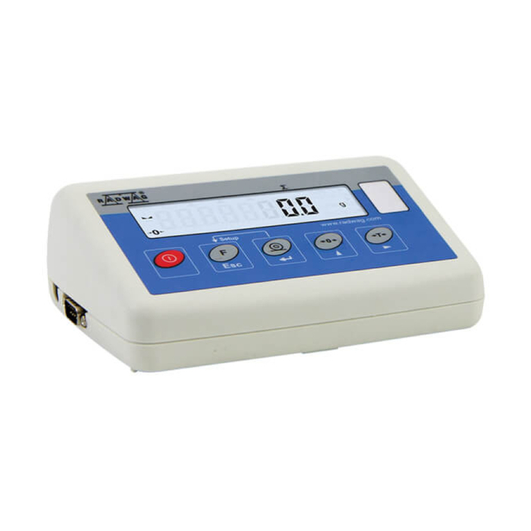
RADWAG PUE C315 User manual


2
APRIL 2021

3
CONTENTS
1. INTENDED USE ................................................................................................................................................. 5
2. WARRANTY CONDITIONS ...............................................................................................................................5
3. MAINTENANCE ACTIVITIES ............................................................................................................................ 5
3.1. Cleaning ABS Components.........................................................................................................................5
3.2. Cleaning Stainless Steel Components........................................................................................................6
4. DESIGN ..............................................................................................................................................................6
4.1. Dimensions..................................................................................................................................................6
4.2. Connectors Arrangement ............................................................................................................................7
4.3. Pins Overview..............................................................................................................................................7
4.4. Operation panel...........................................................................................................................................7
4.5. Technical specifications ..............................................................................................................................8
5. INDICATOR INSTALLATION ............................................................................................................................ 9
5.1. Unpacking and Installation..........................................................................................................................9
5.2. Start-Up .......................................................................................................................................................9
5.3. Battery Charge Status.................................................................................................................................9
5.4. Battery Charge Status Check....................................................................................................................10
5.5. Worn out Batteries Replacement..............................................................................................................10
6. OPERATING THE MENU.................................................................................................................................11
6.1. Return to the Weighing Mode....................................................................................................................11
7. INSTALLER INSTRUCTION............................................................................................................................12
7.1. Connecting 6-Wire Load Cell ....................................................................................................................12
7.2. Connecting 4-Wire Load Cell ....................................................................................................................13
7.3. Connecting Load Cell’s Cable Shield........................................................................................................14
8. FACTORY SETUP............................................................................................................................................ 14
8.1. Access to Factory Setup ...........................................................................................................................14
8.2. Factory Parameters List............................................................................................................................15
8.3. Defining the device....................................................................................................................................17
8.4. Factory adjustment....................................................................................................................................18
8.4.1. External Adjustment Process.........................................................................................................18
8.4.2. Start Mass Determination...............................................................................................................18
8.4.3. Correction of Start Mass Expressed in Converter's Divisions .......................................................19
8.5. Linearity correction....................................................................................................................................19
8.5.1. Entering Linearity Correction Points...............................................................................................19
8.5.2. Corrections .....................................................................................................................................20
8.5.3. Deleting Linearity............................................................................................................................20
8.6. Gravitational coefficient.............................................................................................................................20
9. DIAGRAMS OF CONNECTION CABLES.......................................................................................................21

4
PRECAUTIONS
Prior to installation, use or maintenance activities, carefully read this user
manual and follow the provided guidelines.
Prior to the first use, carefully read this user manual. Use the device only
as intended.
Protect the indicator against considerable temperature variation, solar and
UV radiation, substances causing chemical reactions.
The weighing device must not be operated in hazardous areas
endangered with explosion of gases, andin dusty environments.
In case of damage, immediately unplug the device from the mains.
Scales to be decommissioned must be decommissioned in accordance
with valid legal regulations.
Do not let battery discharge in case of prolonged storage of the device
in low temperature.
Accumulators do not belong to regular household waste. The European
legislation requires discharged accumulators to be collected and disposed
separately from other communal waste with the aim of being recycled.
Symbols on batteries identify harmful compounds: Pb = lead,
Cd = cadmium, Hg = mercury. Dear user, you are obliged to dispose of the
worn out batteries as regulated.

5
1.INTENDED USE
PUE C315 weighing indicator is a device intended to make industrial scales
operating on the basis of load cells. The indicator is equipped with an internal
battery, this allows its operation in places where there is no access to the
mains. Clear weighing result presentation is ensured due to large display
(LCD). Indicator's housing is made of plastic. Standard indicator features
RS232 interface for cooperation with peripheral devices (printer, computer,
etc.), and offers wireless communication.
2.WARRANTY CONDITIONS
A. RADWAG feels obliged to repair or exchange all elements that appear to
be faulty by production or by construction.
B. Defining defects of unclear origin and means of their elimination can only
be realized with assistance of manufacturer and user representatives.
C. RADWAG does not bear any responsibility for damage or losses
resulting from unauthorized or inadequate performing of production
or service processes.
D. The warranty does not cover:
mechanical damage caused by product exploitation other than
intended, damage of thermal and chemical origin, damage caused by
lightning, overvoltage in the power network or other random event,
inappropriate cleaning habits.
E. Loss of warranty takes place if:
a repair is carried out outside RADWAG authorized service point,
service claims intrusion into mechanical or electronic construction by
unauthorized people,
the device does not bear company protective stickers.
F. Warranty conditions outline the warranty period for rechargeable
batteries attached to the device for 12 months.
G. For detailed warranty conditions read the warranty certificate.
H. Contact with the central authorized service: +48 (48) 386 63 30.
3.MAINTENANCE ACTIVITIES
In order to ensure safety in the course of cleaning, it is necessary to disconnect
the device from the mains.
3.1. Cleaning ABS Components
To clean dry surfaces and avoid smudging, use clean non-colouring cloths
made of cellulose or cotton. You can use a solution of water and detergent
(soap, dishwashing detergent, glass cleaner).

6
Gently rub the cleaned surface and let it dry. Repeat cleaning process
if needed.
In the case of hard to remove contamination, e.g. residues of adhesive, rubber,
resin, polyurethane foam etc., you can use a special cleaning agents based on
a mixture of aliphatic hydrocarbons that do not dissolve plastics. Before using
the cleanser for all surfaces we recommend carrying out tests. Do not use
cleansers containing abrasive substances.
3.2. Cleaning Stainless Steel Components
Avoid using cleansers containing any corrosive chemicals, e.g. bleach
(including chlorine). Do not use cleansers containing abrasive substances.
Always remove the dirt using microfiber cloth to avoid damage of protective
coating.
In case of a daily maintenance:
1. Remove the dirt using cloth dipped in warm water.
2. For best results, add a little bit of dishwashing detergent.
4. DESIGN
4.1. Dimensions
Dimensions of PUE C315

7
4.2. Connectors Arrangement
1 –power supply socket
2 –RS232 (1) connector
3 –weighing platform cable inlet
4 –RS232 (2) connector *
*) - option.
4.3. Pins Overview
Pin2 –RxD
Pin3 –TxD
Pin4 –5VDC
Pin5 –GND
RS232 (1) connector, DB9/M (male)
Pin2 –RxD
Pin3 –TxD
Pin4 –5VDC
Pin5 –GND
RS232 (2) connector, DB9/M (male)
4.4. Operation panel

8
Keys:
Press to switch the weighing device on/off –hold the key for about
1 second.
Function key, press to change the working mode.
Press to send the weighing result to a printer or computer.
Press to zero the scale.
Press to tare the scale.
Upon pressing + keys combination, functions
of given keys change. Detailed information concerning use
of the above keys combination is to be found further down
this manual.
4.5. Technical specifications
Housing
Plastic
Ingress protection
IP43
Operating temperature
-10°C do +40°C
Display
LCD (backlit)
Power supply
100 ÷ 240 VAC 50 ÷ 60 Hz / 12-24 VDC
Battery power supply
6 x NiMH AA/R6 batteries
OIML
III
Verification unit [e] quantity
6000
Maximum input signal
39 mV
Minimum voltage per verification unit
0.4 uV
Minimum impedance of load cell
50
Maximum impedance of load cell
1200
Load cell power supply
5 V
Connection of load cells
4 or 6 wires + shield
Weighing platforms quantity
1
Multi range option
Yes

9
Standard interfaces
RS232 (1), Wireless communication
Optional interfaces
RS232 (2)
5.INDICATOR INSTALLATION
5.1. Unpacking and Installation
A. Take the indicator out of the packaging.
B. Connect the indicator and the platform and place the set on a flat and
even surface. Keep it far away from any sources of heat.
C. To level the weighing instrument turn its feet. Keep turning the feet until
the air bubble takes central position:
5.2. Start-Up
The weighing device can be connected to the mains only with a power supply
that comes standard with the particular model. Nominal voltage of the power
supply (specified on the power supply data plate) has to be compatible with the
mains nominal voltage.
Procedure:
Connect the power supply to the mains. Plug it to the power supply socket
(back side of the scale housing).
Press key. The key is also used to switch the scale on/off.
Display test proceeds (all symbols are backlit for a moment), program
name and number is displayed first, mass indication next.
5.3. Battery Charge Status
The scale of standard design is equipped with an internal battery. Battery state
is signalled by pictogram, the pictogram is displayed in the top bar of the
display.

10
pictogram display mode
Meaning
No pictogram
Battery charged. Regular scale operation.
Pictogram displayed continuously
Too low battery charge (the scale is about to shut
down). Charge the battery immediately.
Blinking pictogram, blink frequency:
ca. 1 s
Battery charge in progress. The device is connected
tothe power supply charging the battery.
Blinking pictogram, blink frequency:
ca. 0.5 s
Battery error. Battery is damaged.
5.4. Battery Charge Status Check
Press and keys combination.
Depending on the battery state, a respective status is displayed on the
screen for 2s:
80%
Battery power supply. Battery power given in %.
CHArGE
Battery charge in progress. The device is connected to the power supply
charging the battery.
-Err5-
Battery error. Battery is damaged.
Next, the home screen is displayed automatically.
5.5. Worn out Batteries Replacement
Open battery container lid. The lid is to be
found in the housing base.
Take the worn out batteries out of the
container, insert new accumulators, pay
attention to +/- polarization.

11
Close the lid.
6. OPERATING THE MENU
In order to navigate the program menu use the operation panel.
+
Press to enter the main menu.
+
Press to enter tare manually.
Press to enter tare from tare database.
Press to change value by 1 digit up.
Press to scroll the menu up.
+
Press to check battery/accumulator state.
+
Press to view date/time.
Press to scroll the menu down.
Press to change current parameter value.
Press to enter given submenu.
Press to modify given parameter.
Press to confirm modification.
Press to exit, function remains unmodified.
Press to move one menu level up.
6.1. Return to the Weighing Mode
Introduced menu modifications are automatically saved to scale memory upon
return to the home screen. To return to the home screen press key
repeatedly.

12
7.INSTALLER INSTRUCTION
The PUE C315 indicator serves as basis of load cell scales.
7.1. Connecting 6-Wire Load Cell
Connect 6-wire load cell to the main board following the diagram below:
6-wire load cell connection
RADWAG BOARD SIGNALS
LOAD CELL SIGNALS
NOTES
E
SHIELD
refer to section 7.3
REF+
SENSE+
JP5 not soldered
REF-
SENSE-
JP6 not soldered
IN+
OUTPUT+
IN-
OUTPUT-
+5V
INPUT+
AGND
INPUT-

13
7.2. Connecting 4-Wire Load Cell
Connect 4-wire load cell to the main board following the diagram below:
Connecting 4-wire load cell
RADWAG BOARD SIGNALS
LOAD CELL SIGNALS
NOTES
E
SHILED
refer to section 7.3
REF+
SENSE+
JP5 soldered
REF-
SENSE-
JP6 soldered
IN+
OUTPUT+
IN-
OUTPUT-
+5V
INPUT+
AGND
INPUT-

14
7.3. Connecting Load Cell’s Cable Shield
Load cell with galvanic
connection of the signal
cable shield.
Load cell without galvanic
connection of the signal
cable shield.
Balance with indicator in ABS housing
connected with platform via load cell
signal cable.
Do NOT connect
E
Balance compact design (balance with
indicator in ABS housing on a post).
Do NOT connect
E
E–Solder pad on the main board and on additional A/D converter boards.
8. FACTORY SETUP
To access and modify both factory settings and parameters that are made
available for a user, run Factory Setup mode. Running Factory Setup mode
enables the technician to define the balance.
8.1. Access to Factory Setup
Switch the weighing device off, to do it press key.
Press and hold SW1 switch located on the electronics board, while holding
the SW1 switch, press key to run the weighing device.
Factory Setup access switch

15
Wait, the device switches on.
Press and keys combination, message <P0.FAct> is displayed.
Press key to go to factory parameters' submenu no. 1.
After completed factory parameters setup, restart the
weighing device.
8.2. Factory Parameters List
No.
Name
Value
Description
P0.
FAct
-
Factory parameters
0.1.
Glob
-
Global parameters
0.1.1.
duu
-
Defining the weighing device.
0.1.2.
FAc
Serial number.
0.1.3.
tYP
1, 2, 4, 6, 7, 8, 12
Weighing device type: 1- WLC/A2;
2- WLC/F, WLC/C2, 4–WTC,
6–Medical scale, 7- Medical scale
(BMI disabled), 8–PUE C315;
12 –WLC/C/2.
0.1.4.
Gcor
0.9 - 1.1
Gravity correction factor.
0.1.7.
tSc
SLA, nInnH, no
Battery selection.
0.1.8.
CSt
nonE, d, A, V, b, SP, SC
Declaring the customer: nonE - none,
d- KERN, A- ADEMI, V- VWR,
b- BOECO, SP - Spectrum,
SC –Schuller.
0.1.9.
rtc
-
RTC synchronisation.
0.1.A.
ntE
YES, no
US market metrological requirements
activation.
0.1.b.
UFA
YES, no
Wireless communication module
activation.
0.2.
nnG
-
Metrology
0.2.1.
A/d
-
Converter's divisions.
0.2.2.
Uni
g, kg, lb
Adjustment unit.
0.2.3.
du1
0.0001, 0.0002, 0.0005,
0.001, 0.002, 0.005, 0.01,
0.02, 0.05, 0.1, 0.2, 0.5, 1,
2, 5, 10, 20, 50
Range 1 reading unit.
0.2.4.
dE1
no, 0.001, 0.01, 0.1, 1, 2,
5
Range 1 verification unit; no - non-
verified balance/scale.

16
0.2.5.
du2
0.0001, 0.0002, 0.0005,
0.001, 0.002, 0.005, 0.01,
0.02, 0.05, 0.1, 0.2, 0.5,
1, 2, 5, 10, 20, 50
Range 2 reading unit.
0.2.6.
dE2
no, 0.001, 0.01, 0.1, 1, 2,
5
Range 2 verification unit; no - non-
verified balance/scale.
0.2.7.
Ful
-
Maximum range + overload.
0.2.8.
rn2
-
Range switching point.
0.2.9.
uuE
-
External adjustment weight mass.
0.2.A
uui
-
Internal adjustment weight mass. „0”
- internal adjustment disabled.
0.2.b.
Aur
PrF, 0.1d, 0.2d, 0.25d,
0.5d, 0.6d, 0.7d, 0.8d,
0.9d, 1d, 2d, 2.5d, 3d,
4d,5d,6d, 7d, 8d, 9d, 10d
Autozero range: PrF - value taken
from program-implemented tables;
0.1d - 10d - value entered directly by
a user.
0.2.c.
Aut
PrF, 0, 0.2s, 0.4s, 0.6s,
1s, 2s, 3s, 4s, 5s, 6s, 7s,
8s, 9s, 10s, 15s, 20s,
Autozero time: PrF - value taken from
program-implemented tables; 0s - 20s
- value entered directly by a user.
0.2.d.
Str
PrF, 0.1d, 0.2d, 0.25d,
0.5d, 0.6d, 0.7d, 0.8d,
0.9d, 1d, 2d, 2.5d, 3d,
4d,5d,6d, 7d, 8d, 9d, 10d
Stability range: PrF - value taken from
program-implemented tables; 0.1d -
10d - value entered directly by a user.
0.2.E.
Stt
PrF, 0, 0.2s, 0.4s, 0.6s,
1s, 2s, 3s, 4s, 5s, 6s, 7s,
8s, 9s, 10s, 15s, 20s,
Stability time: PrF - value taken from
program-implemented tables; 0s - 20s
- value entered directly by a user.
0.2.F.
rAn
YES, no, 50%, dEF
Start mass control: YES –range: from
-10% to +10% of start mass, no –off,
50% –range: from -50% to +50% of
start mass, dEF –range declared in
0.2.G. parameter.
0.2.G.
rnt
10% - 90%
Start mass range in [%].
0.2.H.
Ldn
no, YES
Digit marker for non-verified scales.
0.3.
CAL
-
Adjustment
0.3.1.
CLE
-
External adjustment process.
0.3.2.
Std
-
Determination of start mass for
external adjustment.
0.3.3.
CLI
-
Internal adjustment process.
0.3.4.
Stu
-
Start mass expressed in converter's
divisions.
0.3.5.
AdF
-
Adjustment factor.
0.3.6.
CAC
0.1, 1, 2, 3, 4, 5, 6, 7, 8,
9, 10, 11, 12.
Setting time interval, in [h], after which
internal adjustment is triggered.
0.3.7.
CAt
0.1, 0.2, 0.3, 0.4, 0.5, 0.6,
0.8, 1, 1.5, 2, 2.5, 3, 4, 5,
6, 8, 10
Setting temperature difference,
in [C], for which internal adjustment
is triggered.

17
0.3.8.
CAS
-
Internal adjustment weight weighing
procedure.
0.3.9.
CAu
-
Internal weight relocation, up-down
direction.
0.3.A
tP
-
Display of current temperature,
in [C].
0.4.
LinE
-
Linearity
0.4.1.
dSG
-
Entering linearity correction points.
0.4.2.
dEL
-
Deleting linearity.
0.4.3.
Cor
-
Entering correction values for linearity.
0.5.
Boot
Bootloader
0.6.
dFLt
-
Default settings.
8.3. Defining the device
Defining the device at the production stage requires entering basic
balance/scale parameters: serial number, weighing device type, weighing
range.
Procedure:
Enter factory setup <P0.FAct>.
Go to <0.1.Glob / 0.1.1.duu> submenu, text <Cont?> is displayed.
Press key, text <nr FAc> is displayed, next you see window
for entering the serial number.
Enter the serial number, do it using the operation panel.
Press key to confirm, text <type> is displayed, next you see window
for balance/scale type selection.
Select balance/scale type, do it using operation panel (refer to factory
parameters table, section 8.2 of this manual).
Press key to confirm, weighing range window is displayed.
Select appropriate weighing range, do it using the operation panel.
Press key to confirm, <0.1.1duu> submenu is displayed.
Exit to home screen, to do it press key repeatedly.

18
While defining balance/scale type, additional parameters are
set automatically. These are among many battery type,
internal adjustment accessibility, additional modules and
communication interfaces accessibility.
8.4. Factory adjustment
8.4.1. External Adjustment Process
Enter factory setup submenu: <P0.FAct / 0.3.CAL>.
Enter <0.3.1.CLE> function, text <UnLoAd> is displayed.
Unload the weighing pan.
Press key, adjustment zero point gets determined.
With adjustment zero point determined, first text <LoAd>, next mass of an
adjustment weight that is to be loaded onto the weighing pan is displayed.
Load the weighing pan with the required adjustment weight.
Press key, adjustment starts.
Upon adjustment completion, text <UnLoAd> is displayed.
Unload the weighing pan, <0.3.1.CLE> submenu is displayed.
Exit to home screen, to do it press key repeatedly.
8.4.2. Start Mass Determination
Enter factory setup submenu: <P0.FAct / 0.3.CAL>.
Enter <0.3.2.Std> function, text <UnLoAd> is displayed.
Unload the weighing pan.
Press key, start mass determination starts.
Upon completed determination process, <0.3.2.Std> submenu is
displayed.
Exit to home screen, to do it press key repeatedly.
If start mass determination or adjustment factor
determination takes more than 360 seconds then <Err8>
error is displayed and short sound signal is heard. In such
case the balance requires readjustment/recalibration,
perform it providing as stable ambient conditions as
possible!

19
8.4.3. Correction of Start Mass Expressed in Converter's Divisions
Enter factory setup submenu: <P0.FAct / 0.3.CAL>.
Enter <0.3.4.Stu> submenu, value of start mass expressed in converter's
divisions is displayed.
Correct the value, to do it use operation panel, next press key to
confirm changes.
Exit to home screen, to do it press key repeatedly.
8.5. Linearity correction
Prior linearity correction it is necessary to determine real balance
characteristics. Correction mechanism allows to enter corrections in 20 points
maximum.
8.5.1. Entering Linearity Correction Points
Enter factory setup submenu: <P0.FAct / 0.4.Line / 0.4.1.dSG>, text
<Cont?> is displayed.
Press key to confirm. Text <Pnt1> is displayed (linearity connection
point no. 1).
Press key, window for entering mass value for linearity correction
point no. 1 is displayed.
Enter the given value, next press key to confirm, text <Pnt2>
is displayed (linearity connection point no. 2).
Press key, the program automatically suggests value for the next
linearity correction point.
Press key to confirm the suggested value, or enter a new value (do it
using operation panel).
Keep repeating this procedure until you enter value close to maximum
capacity value.
While attempting to enter correction point value greater than
maximum capacity value, <Err Hi> error is signalled.

20
In order to finish entering linearity correction points press key,
<0.4.1.dSG> submenu is displayed.
8.5.2. Corrections
It is possible to enter extra corrections for declared linearity correction points.
Procedure:
Enter factory setup submenu: <P.0.FAct / 0.4.Line / 0.4.3.Cor>, value
of linearity correction point no.1 is displayed.
Press key, window for entering correction value for linearity correction
point no. 1 is displayed.
If there is a need to enter negative value, go to the first digit and press
key.
Press key to confirm, modified correction point value is displayed.
Go to the next linearity correction point, to do it press key.
Correcting the 2nd linearity correction point is analogous.
In order to finish correcting linearity correction points press key,
<0.4.3.Cor> submenu is displayed.
8.5.3. Deleting Linearity
Enter factory setup submenu: <P.0.FAct / 0.4.Line / 0.4.2.dEL>, text
<Cont?> is displayed.
Press key for confirmation.
Exit to home screen, to do it press key repeatedly.
8.6. Gravitational coefficient
The function of gravity correction compensates changes of gravity force being
a result of different latitude. It allows to carry out correct balance/scale
calibration away from the point of subsequent use. The gravity correction value
must be entered with reference to tables prepared by „Radwag Balances and
Scales” or calculated using the below formula:
Other manuals for PUE C315
3
Table of contents
Other RADWAG Accessories manuals

RADWAG
RADWAG PUE HX7 User manual

RADWAG
RADWAG PUE C315 User manual

RADWAG
RADWAG PUE C32 User manual

RADWAG
RADWAG PUE HX7 User manual

RADWAG
RADWAG PUE C32 User manual

RADWAG
RADWAG PUE 5.15 User manual

RADWAG
RADWAG HRP 16 User manual

RADWAG
RADWAG PUE H315 User manual

RADWAG
RADWAG PUE C32 User manual

RADWAG
RADWAG PUE HY10 User manual