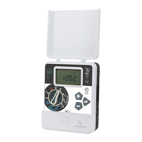
Rain i-dial User manual

N N O V A T I V E I R R I G A T I O N S Y S T E M S
I
EN. INSTRUCTIONS
Vac

ENGLISH
RAIN s.p.a.
via Kennedy 38/40
20023 Cerro Maggiore
ITALY (MI)
16
INDICE
Pag. 17
TECHNICAL FEATURES
Pag. 18
THE CONTROLLER
Pag. 20
ELECTRICAL CONNECTIONS
Pag. 23
INSTALLING THE BATTERIES
CURRENT TIME AND DAY SETTING
Pag. 24
IRRIGATION PLANNING
Pag. 25
MANUAL START
Pag. 26
FUNZIONI AGGIUNTIVE - BUDGET
Pag. 27
ADDITIONAL FEATURES - EXTRA
PUMP
SENSOR
Pag. 28
PROBLEM SOLVING
DESCRIPTION
The new controller I-DIAL, available in
indoor and outdoor version 4-6-8 stations,
is ideal for all residential applications and
follows the philosophy to simplicity of
programming in 3 RAIN steps: start time,
duration and frequency.

ENGLISH
17
Technical features INDOOR version
• 4 - 6 - 8 stations
• indoor Model with external transformer
• Operating 220 VAC 50Hz
• Outputs 24 Volts AC, 0.8 AMP
• 4 independent programs
• 4 start times per program (one for each
program)
• Display of next irrigation
• Irrigation time from 1 min. 240 min. per station
• Watering cycles from 4 per day to 1 per week
• Irrigation program per weekly days or per
intervals from 1 to 19 days
• Seasonal adjustment from 10% to 200%
• Pump control and master valve (24 VAC out)
programmable per station
• Buffer batteries 2 x 1.5 volt AA alkaline (not
included)
• Output rain sensor programmable per station
• Function OFF
• Function Low-battery
• No permanent memory
Technical features OUTDOOR version
• 4 - 6 - 8 stations
• Model outdoor with internal transformer
• Operating 220 VAC 50Hz
• Outputs 24 Volts AC, 1.0 AMP
• 4 independent programs
• 4 start times per program (one for each
program)
• Display of the next irrigation
• Irrigation time from 1 min. 240 min per station
• Watering Cycles 4 per day to 1 week
• Irrigation program per weekly days or per
intervals from 1 days to 19 days
• Seasonal adjustment from 10% to 200%
• Pump control and master valve (24 VAC out)
programmable per station
• Buffer batteries 2 x 1.5 volt AA alkaline (not
included)
• Output rain sensor programmable per station
• Function OFF
• Function Low-battery
• No permanent memory

ENGLISH
18
A
B
C
16
17
18
D
E
24 vacsensor c c m 12345678
SPA
TIME
START
RAIN DELAY
DURATION
WE
EVERY
TU
ALL
MO
DAY
%
SA
ZONE
FRTH SU
BA
HOURS
C D
LOW
PROG
NEXT START
FERTILIZER
1 2 3
4
5 6 7 8
9
10
11
12
13
1415
indoor
model
outdoor
model
WARNING
The version with the outside transformer
must be installed in shelter of weather
THE CONTROLLER

ENGLISH
19
Dial
A
When the dial is in this position the control-
ler do the irrigation as programming
When the dial is in this position you
can set time and date.
When the dial is on one of these
symbols you can set a start time irrigation
When the dial is on one of these symbols
you can set the watering duration of the
indicated sector
When the dial is on one of these symbols
you can set days or the frequency
irrigation
Programming button
B
Increases the selected item fl ashing in the
display
Confi rms values and let continue the pro-
gramming (ENTER)
Decreases the selected item fl ashing in the
display
Wiring Compartment
C
24 vac Cables transformer Input
sensor Rain sensor input
Pump control or master valve Output
M
Sector output
1...8
The button CLEAR eliminates programming
16
Protection fuse 1.0 A
17
button RESET restarts the controller
18
Extra bottons
D
It allows manual start irrigation
It allows you to personalize the start of
pump and sensor
It allows to adjusts irrigation times with a
percentage
Schermo retro illuminato
E
1 Il sensore pioggia è attivo
2 Le batterie tampone sono scariche
3 E’ attiva la funzione ritardo dell’irrigazione
4 Funzione non disponibile
5 Indica la prossima partenza
6 Indica l’ora di partenza
7 Indica i programmi
8 Indica un’irrigazione in corso
9 Indica la regolazione stagionale attiva
(budget)
10 Ore
11 Giorno
12 Indica il tempo d’irrigazione
13 Giorni della settimana
14 Indica l’intervallo d’irrigazione
15 Indica l’irrigazione manuale in corso

ENGLISH
20
OFF
SPA
OFF
OFF
OFF
Elettrovalvola
zona 1
Elettrovalvola
zona 2
Elettrovalvola
zona 3
Elettrovalvola
zona 4
Filo comune
Cavo 24 vac
Cavo sensore
Each 24 VAC electric valve is equipped with two black cables. The fi rst one identifi es the number of
the area and it will be connected to one of the outputs numbered in the terminal compartment and
the second one is the common cable that will be connected to the Exit C in the terminal compart-
ment along with all common cables of all electric valves.
The cables of the 24 Vac electric valves have no polarity. Connect the sensor wires to two cables in
output SENSOR. For version INDOOR connect transformer’s cables to the 24-vac input.
ELECTRICAL CONNECTIONS

ENGLISH
21
OFF
OFF
• If the distance between the timer and valves is
less than 700 feet (210 M), use
WaterMaster® sprinkler wire or 20-gauge
(AWG) plastic jacketed thermostat
wire to connect the timer to the valves. If the
distance is over 700 feet (210 M),
• use 16-gauge (AWG) wire. Terminals accept
up to 14-gauge wire. The wire
can be buried in the ground; however, for more
protection wires can be pulled
through PVC pipe and buried underground. Be
careful to avoid burying the wires
in locations where they could be damaged by
digging or trenching in
the future.
• Each valve has two wires. One wire is to be
connected as the common. The
common wires for all the valves can be connec-
WIRING THE ELECTRIC VALVES
ted together to one common wire
CONNECTING VALVE WIRES TO THE
TIMER
• Remove the terminal compartment cover.
• Strip _” (6mm) of the plastic insulation off the
end of each wire.
• Determine which valve you want to connect to
which station. Connect each
valve wire to its station terminal (labeled 1-6) by
inserting the bare wire fully into
the terminal.
going to the timer. The other valve wire is to be
connected to the specifi c station wire that will
control that valve
• All wires should be joined together using wire
nuts, solder, or vinyl tape. For additional protec-
tion to waterproof connections a WaterMaster®
grease cap can be used
• To avoid electrical hazards, only one valve
should be connected to each station (Note:
Only one wire can be installed into each termi-
nal. If more than two common wires are used
in your system, splice several together so only
one wire runs into each of the COM terminals.
Protect the splice connection with a wire nut.)

ENGLISH
22
• It will be necessary to open the terminal to
allow for wire insertion or removal.
To do this you will need to use a small phillips
head screwdriver.
• Connect the common wire to the terminal
labeled “com”
CONNECTING THE TRANSFORMER
• With the wiring terminal shroud off, fi nd the
two terminal holes labeled “24vac”.
Make sure the transformer is not plugged in.
Insert one of the two power leads
from the transformer into each terminal.
• It will be necessary to open the terminal to
allow for wire insertion or removal.
To do this you will need to use a small phillips
head screwdriver.
• Plug in transformer
WARNING: DO NOT LINK TWO OR MORE
TIMERS TOGETHER WITH ONE
TRANSFORMER.
• Slide the shroud back on.
RAIN SENSOR
• A rain sensor or other type of micro-switch
weather sensor may be connected to
the controller. The purpose of the sensor is to
stop watering when precipitation is
suffi cient.

ENGLISH
23
SPA
TIME
MO
CURRENT TIME AND DAY SETTING
Turn the circular cursor on SET, the time will begin to
fl ash.
Modify the time with the + and - buttons, then press
ENTER to confi rm and move to the modifi cation of
minutes with + and -, press ENTER to confi rm and move
to the modifi cation of the day of the week with
+ and - buttons, press ENTER to confi rm.
After adjusting the time you can turn the cursor to the
right to continue with the watering cycles programming
or to the left to return to the auto function.
INSTALLING THE BATTERIES
Remove the battery compart-
vano batterie
ment by unscrewing the two
screws on the edges. Put two
AA (1.5 V) alkaline batteries in
the compartment.
Replace the battery compart-
ment in its place
and screw.
vano batterie
AA 1.5 V
AA 1.5 V
batterie
non fornite

ENGLISH
24
Turn the dial on the symbol DURATION ZONE, the
irrigation time will begin to fl ash. Modify the minutes of
irrigation with the + and - buttons (you can irrigate from
a minimum of 1 min to a maximum of 240 min) press
ENTER to confi rm and move to the change of the area
2. Repeat the procedure for all zones.
Step 2: Duration setting for each zones
(duration zone)
SPA
DURATION ZONE
A
PROG
duration
zone
N.B. Please note that if the duration of a zone 0, the electric
valve will continue to be closed.
SPA
TIME
START
A
PROG
The controller I-Dial is equipped with 4 programs (A, B,
C, D) completely independent and programmable by
following three simple steps.
Each program allows a daily start and can be combined
with one or more electric valves.
The start time identify the opening of the fi rst electric
valve coupled with the program, the opening of next
electric valves will occur sequentially.
Turn the circular cursor on the symbol START TIME, the
start time will begin to fl ash. Modify the time with the
+ and – buttons and press ENTER to confi rm and move
to the modifi cation of minutes with the + and - buttons
and press ENTER to confi rm.
IRRIGATION PLANNING
Step 1: Start time setting
(start time)
start time

ENGLISH
25
MANUAL START
Pressing the MANUAL button you can irrigate without
start time setting. This allows you to try the system and
its functionality or run an extra irrigation in hot days.
ALL SPA
ALL
ZONE
manual
ALL
Please note that it is not possible to modify the parameter 3
Pressing the MANUAL button the writing ALL will start
minutes in this function.
to fl ash, pressing ENTER button all areas will b open in
succession for 3 minutes. (It’s not possible to modify the
parameter 3 minutes in this function).
Turn the circular cursor on the symbol WATERING
DAYS, the message MO will start to fl ash. Press + to
irrigate in the day fl ashing, press ENTER to continue in
the next days press - if you want to deselect a day.
If you want to irrigate in alternate days press EXTRA and
select the desired interval with the + and - button and
press ENTER
to confi rm. In this function it is possible to irrigate from
once a day to once every 19 days.
I this section it will be possible to choose watering days
through the selection of the days of the week or throu-
gh an interval irrigation.
Step 3: watering days setting
(watering days)
watering
days
SPA
TIME
START
WE
TU
MO SA
FRTH SU
A
PROG

ENGLISH
26
ADDITIONAL FEATURES - BUDGET
Pressing the BUDGET the written 100 will start to fl
ash
and you can change the value with the + and – buttons
and pressing ENTER you will confi rm the value and
return to the home screen.
The function BUDGET allows to modify simultaneously
all irrigation times in percentage. You can change the
percentage from a minimum of 10% to a maximum of
200%.
Attention: When the function BUDGET is changed, the symbol
% remains visible on the main screen. Only if the percentage
BUDGET is 100% the symbol % is not displayed.
If the percentage is changed, watering times will be changed in
the function DURATION ZONE.
No change watering times with the function BUDGET different
from 100%.
SPA
%
%
budget
EXAMPLE: the controller is programmed to per-
form a watering cycle at 07:00 AM with irrigation
times of 10 minutes per zone. If we reduce the
percentage of irrigation (BUDGET) to 70%, the
controller perform an irrigation cycle at 07:00 AM
with watering times of 7 minutes per area.
SPA
ALL
ZONE
manual
zone
Pressing the MANUAL button the written ALL will start
to fl ash, pressing the + button you can set the duration
of the manual irrigation of the area 1, press ENTER to
confi rm and set the duration of the manual irrigation for
next areas.
Please note that to start the manual irrigation it’s necessary
to continue to press ENTER until the last programmable
zone. If you do not want to start in Manual irrigation some
areas leave setting 0.
Please note that the set times in this function are not stored.

ENGLISH
27
SPA
Pressing the EXTRA button 2 times the written SEnS
will begin to fl ash, press enter to access the function,
modify with + or – buttons the word ON/OFF fl ashing
and press ENTER to confi rm and move to the next zone.
To return to the Initial screen press again EXTRA.
ADDITIONAL FEATURES - EXTRA
Pressing the EXTRA button it will be possible to modify
the function Pump and function SEnS.
In these two functions you can set the start of
the pump or turn on/off the sensor rain for single zone.
SPA
Pressing the EXTRA button, the written Pump will begin
to fl ash, press ENTER to access the function, modify
with the + or – buttons the word ON/OFF fl ashing and
press ENTER to confi rm and move to the next zone. To
return to the Initial screen press again EXTRA.
EXAMPLE: The garden is composed of four
areas here: 3 zones for watering of the lawn with
sprinklers connected to a
pump and one area for watering of fl owers under
the porch with drip connected to an aqueduct
For the three areas with sprinklers you have to turn
on the function SEnS and the function Pump.
For the area with the drip pump I have to turn off
the function SenS and PUmP.
Please note that Selecting ON in the function Pump the
output Pump of the terminal will remain energized for the
whole duration of the irrigation of the area feeding the relay
connected to the pump.

ENGLISH
28
Problem Causes Solution
The display shows
“No AC”
There is no AC power (the
programmer
is not powered)
Check that the fuse is intact.
Check that the transformer is
connected properly
The rain sensor
does not stop the
system
• Rain sensor defective
• Stations have been program-
med to keep out the sensor
• Verify the operation of the
rain sensor and correct cabling
system
cablatura dell’impianto
• Program again the exclusion
of the sensor to activate it
The Display is
blocked or shows
incorrect informa-
tion
Peak voltage Reset the programmer
The controller irri-
gates endlessly
Too many start times have
been programmed
Set up again the controller
PROBLEM SOLVING Any unauthorized changes of this
Warning:
units that are not expressly approved by the re-
sponsible for compliance could cancel the right
to make use of this equipment
NOTE: This device has been tested and com-
plaint declared with imposed limits on Class B,
Part 15 digital devices provided for the FCC Ru-
les.
These limits are designed to provide a reasonable
protection against harmful interferences in a resi-
dential location.
This equipment generates, uses, and can
emit radio frequency energy and, if not used
and installed in compliance with the instructions,

ENGLISH
29
may cause an interference to radio communica-
tions. However, we cannot
exclude that any interferences happen.
If this equipment causes interferences to
radio or television reception, which can be de-
termined turning on and off the equipment, the
user has to take the following measures to try to
eliminate them:
Reorient or relocate the receiving antenna.
• Increase the separation between device and
receiver.
• Connect the equipment to a socket of a circuit
different from the circuit to which the receiver is
connected.
• Consult the dealer or an experienced radio / TV
technician.
Warning: This device is not designed
for use by children or disable people
without supervision. Supervise children
to avoid that they play with the device.
Caution: Relay activation pump and the main
valve
The controller allows you to operate a master
valve or a pump during operation of any station.
Connect a relay cable * (or master valve) to the
“pump” and the other cable to the “common”
exit of the controller.
* relay activation of the pump sold separately
Warranty and Declarations
RAIN spa, guarantees its customers that its pro-
ducts will be free from defects in materials and
manufacturing for a period of two years from the
purchase date.
For a period of two years from the purchase
date we replace defective parts free of charge
or components that will reveal defects if used in
the normal conditions of use and maintenance
(requiring proof of purchase).
We reserve the right to inspect the defective part
before replacing it.
RAIN spa will not be responsible for any costs or
accessories or consequential damages, caused
by a defect of the product.
The responsibility of RAIN spa under this
warranty is limited only to the replacement
of defective components.
To exercise your right to warranty, return the unit
to your dealer with a copy of the receipt of
payment.
Other manuals for i-dial
1
Table of contents
Other Rain Controllers manuals
Popular Controllers manuals by other brands

HKS
HKS EVC7 instruction manual

Belimo
Belimo PRCA-S2-T Technical data sheet

Avigilon
Avigilon AC-HID-LSP-ACMEC-KIT4 installation guide

Zennio
Zennio ZCL-MCC user manual

Regal-Beloit
Regal-Beloit Marathon Electric PM300 instruction manual

ENAPART
ENAPART WILKERSON Dial-Air r5 Installation & service instructions