Table of contents | 4
+44 (0) 1527 396900 / info@ratioev.uk / www.ratioev.uk
Table of contents
1. Safety 5
1.1. Symbols and labels 5
1.1.1. Safety warnings 5
1.1.2. Fuel Identifier 5
1.1.3. Notices 6
1.2. Intended use 6
1.3. Reasonably foreseeable misuse 6
1.4. Qualification of personnel 7
1.5. Personal Protective Equipment 7
1.6. Safety Precautions 7
2. Product description 9
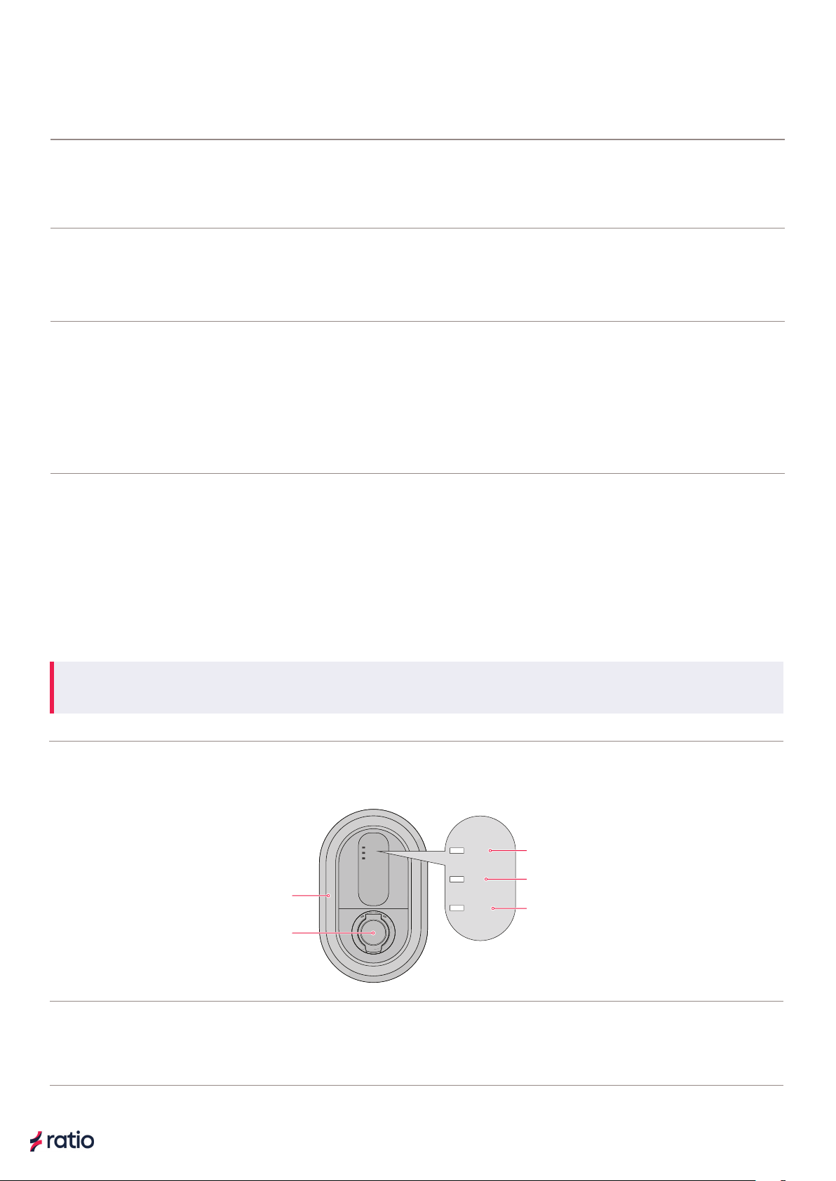
2.1. Charger Components 10
2.2. Sensor Box components (Optional for Smart charger) 11
3. Technical data 12
3.1. Product Labelling/Marking 13
4. Transport and Storage 13
4.1. Transport 13
4.2. Storage 13
5. Installation 13
5.1. Preparation 13
5.1.1. Check the contents 14
5.1.2. Required tools 15
5.1.3. Required wiring and electrical protection 15
5.2. Install the power cable in the distribution board 16
5.3. Install the Sensor Box in the consumer unit 16
5.4. Charger Installation/Mounting 19
5.5. Connect the power cable to the charger 20
5.6. Ethernet cable installation 24
5.7. Data cable installation 25
5.8 Install a data cable between two chargers for Power Sharing 27
5.8.1. In the Main Controller 27
5.8.2. In the Sub charger 28
5.9. Final installation checks 30
5.10. Finish the installation 31
6. Commissioning 32
6.1. The unique password of the charger 32
6.2. Download the Ratio EV Charging App 32
6.3. Initial configuration of the charger 32
6.4. Overview of the Ratio EV Charging App 34
6.5. Connect the charger to the Ratio EV Charging App 34
6.6. Testing solar charging functionality 35
6.7. Updating the charger 35
7. Using the io5 36
7.1. Start charging 36
7.2. During charging 37
7.2.1. Charging paused 37
7.3. Stop charging 37
8. Settings 37
9. Maintenance 39
10. Troubleshooting 40
11. Service 42
12. Data protection 42
13. Warranty 42
14. Disposal 42
15. EC Declaration of Conformity 43
1.2. Intended use 61.2. Intended use 6
4. Transport and Storage 134. Transport and Storage 13
5.3. Install the Sensor Box in the consumer unit 165.3. Install the Sensor Box in the consumer unit 16
5.9. Final installation checks 305.9. Final installation checks 30
6.5. Connect the charger to the Ratio EV Charging App 346.5. Connect the charger to the Ratio EV Charging App 34
1.4. Qualification of personnel 71.4. Qualification of personnel 7
4.2. Storage 134.2. Storage 13
5.5. Connect the power cable to the charger 205.5. Connect the power cable to the charger 20
6.7. Updating the charger 356.7. Updating the charger 35
7.2.1. Charging paused 377.2.1. Charging paused 37
10. Troubleshooting 4010. Troubleshooting 40
14. Disposal 4214. Disposal 42
1.1.1. Safety warnings 51.1.1. Safety warnings 5
1.1.2. Fuel Identifier 51.1.2. Fuel Identifier 5
3. Technical data 123. Technical data 12
5.1.3. Required wiring and electrical protection 155.1.3. Required wiring and electrical protection 15
5.8.1. In the Main Controller 275.8.1. In the Main Controller 27
6.3. Initial configuration of the charger 326.3. Initial configuration of the charger 32
1.1.3. Notices 61.1.3. Notices 6
3.1. Product Labelling/Marking 133.1. Product Labelling/Marking 13
5.2. Install the power cable in the distribution board 165.2. Install the power cable in the distribution board 16
5.8.2. In the Sub charger 285.8.2. In the Sub charger 28
6.4. Overview of the Ratio EV Charging App 346.4. Overview of the Ratio EV Charging App 34
1.3. Reasonably foreseeable misuse 61.3. Reasonably foreseeable misuse 6
4.1. Transport 134.1. Transport 13
5.4. Charger Installation/Mounting 195.4. Charger Installation/Mounting 19
5.10. Finish the installation 315.10. Finish the installation 31
6.6. Testing solar charging functionality 356.6. Testing solar charging functionality 35
7.2. During charging 377.2. During charging 37
9. Maintenance 399. Maintenance 39
11. Service 4211. Service 42
1.5. Personal Protective Equipment 71.5. Personal Protective Equipment 7
5. Installation 135. Installation 13
5.6. Ethernet cable installation 245.6. Ethernet cable installation 24
7. Using the io5 367. Using the io5 36
7.3. Stop charging 377.3. Stop charging 37
12. Data protection 4212. Data protection 42
15. EC Declaration of Conformity 4315. EC Declaration of Conformity 43
13. Warranty 4213. Warranty 42
1.6. Safety Precautions 71.6. Safety Precautions 7
5.1. Preparation 135.1. Preparation 13
5.7. Data cable installation 255.7. Data cable installation 25
6. Commissioning 326. Commissioning 32
7.1. Start charging 367.1. Start charging 36
8. Settings 378. Settings 37
2. Product description 92. Product description 9
2.1. Charger Components 102.1. Charger Components 10
5.1.1. Check the contents 145.1.1. Check the contents 14
5.8 Install a data cable between two chargers for Power Sharing 275.8 Install a data cable between two chargers for Power Sharing 27
6.1. The unique password of the charger 326.1. The unique password of the charger 32
1.1. Symbols and labels 51.1. Symbols and labels 5
2.2. Sensor Box components (Optional for Smart charger) 112.2. Sensor Box components (Optional for Smart charger) 11
5.1.2. Required tools 155.1.2. Required tools 15
6.2. Download the Ratio EV Charging App 326.2. Download the Ratio EV Charging App 32