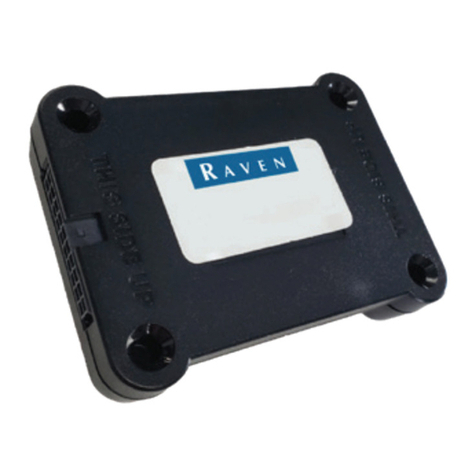
Raven Phoenix 300 User manual

Phoenix 300™ DPGS Receiver with
USB Installation and Operation
Manual
P/N 016-0171-548 Rev. C 04/15 E23137
Copyright 2015

While every effort has been made to ensure the accuracy of this document,
Raven Industries assumes no responsibility for omissions and errors. Nor is any
liability assumed for damages resulting from the use of information contained
herein.
Raven Industries shall not be responsible or liable for incidental or consequential
damages or a loss of anticipated benefits or profits, work stoppage or loss, or
impairment of data arising out of the use, or inability to use, this system or any of
its components. Raven Industries shall not be held responsible for any
modifications or repairs made outside our facilities, nor damages resulting from
inadequate maintenance of this system.
As with all wireless and satellite signals, several factors may affect the availability
and accuracy of wireless and satellite navigation and correction services (e.g.
GPS, GNSS, SBAS, etc.). Therefore, Raven Industries cannot guarantee the
accuracy, integrity, continuity, or availability of these services and cannot
guarantee the ability to use Raven systems, or products used as components of
systems, which rely upon the reception of these signals or availability of these
services. Raven Industries accepts no responsibility for the use of any of these
signals or services for other than the stated purpose.
Disclaimer
©Raven Industries, Inc. 2013, 2014

Table of Contents
Manual No. 016-0171-548 Rev. C i
Chapter 1 Introduction............................................................................. 1
Receiver Overview ....................................................................................................................1
USB Capability ....................................................................................................................1
Updates ...............................................................................................................................2
Overview of DGPS Systems .....................................................................................................2
Sources of Error ..................................................................................................................3
Differential GPS (DGPS) Correction Sources .....................................................................3
Chapter 2 Installation and Initial Start Up.............................................. 7
Mounting GPS Receiver Equipment .........................................................................................7
DGPS Receiver ...................................................................................................................7
DGPS Antenna Mounting ....................................................................................................7
Powering the GPS Receiver .....................................................................................................8
Initial Startup ..............................................................................................................................9
Subscription Services ..........................................................................................................9
Normal Operation ......................................................................................................................9
Chapter 3 Display Menus....................................................................... 11
Overview ................................................................................................................................. 11
Home Display Screen .............................................................................................................12
OmniSTAR® XP/HP Restart .............................................................................................13
Receiver Display Menu ...........................................................................................................13
Receiver Information .........................................................................................................13
GPS Engine Information ....................................................................................................14
GPS Display Menu ..................................................................................................................15
GPS Signal Information .....................................................................................................15
Dilution of Precision (DOP) Information ............................................................................16
Position Information ...........................................................................................................16
Speed and Course Over Ground (COG) Information ........................................................17
Standard Deviation Information .........................................................................................17
OmniSTAR® Display Menu .....................................................................................................18
Carrier and Signal Status ..................................................................................................19
Virtual Base Station Subscription Information ...................................................................19
OmniSTAR HP Expiration Information ..............................................................................20
OmniSTAR Subscription Information .................................................................................20
OmniSTAR Satellite Frequency .........................................................................................20
OmniSTAR Serial Number ................................................................................................21
OmniSTAR Service ID Number .........................................................................................21
RTK Display Menu ..................................................................................................................22

Baseline Information ..........................................................................................................22

Table of Contents
ii Phoenix 300 Installation & Operation Manual
Utility Options Menu ................................................................................................................23
Unit Preset Configuration Settings ....................................................................................23
Pre-Defined Setting Configurations ...................................................................................24
Radar Configurations .........................................................................................................24
Contrast Setting .................................................................................................................25
Backlight Mode ..................................................................................................................25
Simulated Radar Speed Configuration Screens ................................................................26
Chapter 4 Configuration Menus............................................................ 27
Correction Configuration Menu ...............................................................................................27
Correction Source ..............................................................................................................28
SBAS Configuration Menu ......................................................................................................29
Current SBAS Configuration ..............................................................................................29
GS - Satellite Configuration Menu ...........................................................................................30
Accuracy Warning .............................................................................................................30
Beam .................................................................................................................................31
Activation Code .................................................................................................................32
Operating Mode .................................................................................................................32
Expiration Date ..................................................................................................................33
Hours Remaining ...............................................................................................................33
Satellite CNR .....................................................................................................................33
GS - Slingshot Configuration Menu .........................................................................................34
Accuracy Warning .............................................................................................................34
Baud Rate Settings ............................................................................................................35
OmniSTAR® Configuration Menu ...........................................................................................35
Service ID and Region .......................................................................................................36
User Defined Frequency ....................................................................................................37
OmniSTAR Auto-Restart ...................................................................................................38
RTK Configuration Menu .........................................................................................................39
RTK Signal Format ............................................................................................................39
RTK Network .....................................................................................................................40
RTK Smoothing .................................................................................................................40
Baud Rate ..........................................................................................................................41
Output Configuration Menu .....................................................................................................41
Port A Settings ...................................................................................................................42
Port B Settings ...................................................................................................................43
National Marine Electronics Association (NMEA) Messages ............................................44
Chapter 5 Sample NMEA Message Structure...................................... 45

Table of Contents
Manual No. 016-0171-548 Rev. C iii
Chapter 6 Troubleshooting ................................................................... 47
Check the Installation ..............................................................................................................47
Receiver ..................................................................................................................................47
DGPS Antenna ........................................................................................................................48
Testing Voltage ..................................................................................................................48
Testing Resistance ............................................................................................................48
Power ......................................................................................................................................48
Power Connection .............................................................................................................48
Signal Reception .....................................................................................................................49
Specifications ..........................................................................................................................49
Position Accuracy Chart ..........................................................................................................50
Configuration ...........................................................................................................................50
Rear Panel Serial Interfaces .............................................................................................50
APPENDICES
Appendix A Software Updates via the USB Port.................................... 51
Appendix B Feature Authorization via the USB Port ............................. 53

Table of Contents
iv Phoenix 300 Installation & Operation Manual

CHAPTER
1
Manual No. 016-0171-548 Rev. C 1
C hapt er 1
Introduction
Receiver Overview
Thank you for purchasing the Raven Phoenix 300 DGPS receiver with USB. The Phoenix 300 receiver is
designed to provide highly accurate and reliable DGPS navigation and positioning solutions for yield mapping
and monitoring, swathing, custom applications, and other precision farming functions while operating in the
rugged agricultural environment.
The Phoenix 300 receiver is a sophisticated, dual frequency receiver with superior impulse noise performance
while the 120-channel GPS system provides quick and stable satellite acquisition. The Phoenix 300 provides
reliable tracking of GNSS signals automatically using various correction services including satellite based
augmentation systems (SBAS) and terrestrial radio and cellular network services.
The Phoenix 300 receiver features a front panel display for simple configuration and operation. The Phoenix
300 also features two bidirectional RS-232 serial interface ports to provide GPS data to peripheral devices.
USB Capability
The Phoenix 300 receiver with USB features a USB port on the back of the unit which may be used for
updates, feature authorization, and data logging.
Note: This manual contains information on settings and operation of the Phoenix 300 with USB.
Descriptions of operation, features, and settings contained herein may not be applicable to prior
Phoenix 300 hardware revisions. Please contact a local Raven dealer for additional questions
regarding capabilities or further assistance.

Chapter 1
2 Phoenix 300 Installation & Operation Manual
Updates
Updates for Raven manuals as well as software updates for Raven products are available at the Applied
Technology Division web site:
www.ravenhelp.com
Overview of DGPS Systems
While an in-depth study may be required to fully understand Global Positioning Systems, or GPS, a brief
description can be useful to understand the operation and limitations of these systems.
GPS is a general term used for satellite-based, global navigation satellite systems (GNSS) operated and
maintained by various organizations and government agencies around the world. Originally intended for
military purposes, GPS capabilities have been extended to civilian applications and may be used to provide
highly accurate position and navigation information.
A GPS system consists of constellation of satellites above the earth’s surface. Each satellite continually
transmits a coded radio message containing the satellite position and time that the signal is transmitted. A GPS
receiver on the ground then receives signals from several satellites, decodes the messages and calculates a
position in the longitude and longitude coordinate system.
To calculate the position, the receiver uses an equation based upon the following formula:
The equation calculates the time it took for each radio signal to travel from the satellite and reach the GPS
antenna. The rate used in this formula is the known velocity of the radio signals transmitted from each GPS
satellite. Time is determined using a code matching technique within the GPS receiver.
At Raven Industries, we strive to make your experience with our products as rewarding as
possible. One way to improve this experience is to provide us with feedback on this manual.
Your feedback will help shape the future of our product documentation and the overall service
we provide. We appreciate the opportunity to see ourselves as our customers see us and are
eager to gather ideas on how we have been helping or how we can do better.
To serve you best, please send an email with the following information to
-Phoenix 300 Installation & Operation Manual
-Manual No. 016-0171-548 Rev. C
-Any comments or feedback (include chapter or page numbers if applicable).
-Let us know how long have you been using this or other Raven products.
We will not share your email or any information you provide with anyone else. Your feedback
is valued and extremely important to us.
Thank you for your time.
DISTANCE RATE TIME×=

Manual No. 016-0171-548 Rev. C 3
Introduction
1
Sources of Error
Accuracy of a GPS receiver depends upon the ability of the receiver to correctly calculate the time signals from
each satellite take to reach the GPS antenna. There are several natural conditions which can introduce error
into this calculation and may cause problems when operating any GPS navigation system or receiver.
Four of the primary sources which can introduce errors are:
•Ionospheric and tropospheric delays on the radio signal
•Signal multi-path or reflection
•Receiver clock biases
•Orbital satellite (ephemeris) position errors
GPS is a line-of-sight system which means that a clear path must exist between the satellite and the GPS
antenna. Obstructions such as buildings, trees, parts of the vehicle like a fiberglass or metal roof, and human
bodies may interfere or completely block signals from the GPS receiver. Moreover, items such as electrical
motors, generators, alternators, strobe lights, radio transmitters, microwave dishes, radar, other active
antennas, etc., all generate electrical and magnetic fields which can interfere with GPS or L-Band signals.
Differential GPS (DGPS) Correction Sources
A correction signal or differential source from a known, stationary location on the surface of the earth may be
used to correct for the common sources of error and may also be capable of enhancing the accuracy and
precision of a GPS receiver. The following sections offer brief descriptions of the available differential
correction sources which may be used with the Phoenix 300 receiver.
SBAS (Satellite Based Augmentation System)
Regional SBAS corrections are differential services administrated by various private and government agencies
around the world. Many of these services are available without subscription or cost for agricultural use.
FIGURE 1. Regional SBAS Correction Sources
Note: Using SBAS corrections outside of the coverage areas indicated above can significantly degrade
the position solution provided by the Phoenix 300 receiver.
WAAS
EGNOS
SDCM
MSAS/QZSS
GAGAN

Chapter 1
4 Phoenix 300 Installation & Operation Manual
The Phoenix 300 is compatible with the following SBAS differential correction services:
WAAS (Wide Angle Augmentation System). A correction service primarily covering the United States and
available, without subscription, for agricultural use. WAAS corrections may also be used in some areas of
Canada and Mexico.
More information is available at the Federal Aviation Administration (FAA) web site:
www.faa.gov
EGNOS (European Geostationary Navigation Overlay Service). Correction services which use the GPS
satellite network developed by the U.S. and augmented to provide differential corrections within European
countries.
More information is available at the European Space Agency (ESA) web site:
www.esa.int
SDCM (System for Differential Corrections and Monitoring). SDCM is an SBAS which utilizes both the
GPS and GLONASS satellite constellations for positioning data developed by the Russian government.
More information may be found at the Russian system of differential correction and monitoring web site:
www.sdcm.ru/
MSAS (Multi-functional Satellite Augmentation System). Service developed for differential corrections in
Japan.
QZSS (Quasi-Zenith Satellite System). A system parallel with the MSAS services in Japan.
More information available at the QZSS web site:
www.qzs.jp
GAGAN (GPS Aided Geo Augmented Navigation). Regional SBAS system available for use in India.
More information available at the European Space Agency (ESA) web site:
www.esa.int
NovAtel GLIDE
The NovAtel GLIDE feature can be used either in conjunction with a SBAS correction signal as a position
smoothing feature or as an autonomous correction source for areas with limited SBAS coverage. Both options
are available as a standard feature of the Phoenix 300 receiver.
GS
The GS subscription service delivers corrections without the need for a local reference station. GS corrections
may be delivered to the vehicle cabin either via a satellite based correction signal or via a cellular network and
the Slingshot®Field Hub™.
The Field Hub provides a link for wireless communication from the vehicle cabin via the cellular network and
provides access to the internet via a Raven field computer or other web enabled devices.
Note: GPS engine firmware OEM 6.400 or newer and an authorization code are required for GS
correction services. Refer to the Receiver Display Menu section on page 13 for assistance with
verifying the firmware version installed on the receiver or contact a local Raven dealer for
information on correction services available for Phoenix 300 receivers.

Manual No. 016-0171-548 Rev. C 5
Introduction
1
OmniSTAR
®
VBS, XP, or HP
The OmniSTAR system is a full-time differential GPS broadcast system, delivering corrections to the world’s
major land masses from a worldwide array of reference sites. Data from these reference sites flows to Network
Control Centers (NCC’s) where the corrections are decoded, checked, and repackaged in a highly efficient
format for broadcast. The data is then up converted for transmission to communication satellites which
broadcast over geographical areas. Communication links with each reference site include a dial-up line to
serve as backup to leased lines to allow control of the receivers.
The satellite broadcast is received at the machine location, demodulated, and passed to a processor that
reformats the data into corrections for use by the Phoenix 300 receiver. When using an OmniSTAR correction
service, atmospheric corrections are applied to the data from multiple sites which are then combined to provide
an optimal correction for the machine location. These corrections, recast in RTCM SC-104 format, are used by
the Phoenix 300 receiver for maximum accuracy.
Note: Contact OmniSTAR for details and subscription information.
RTK (Real-Time Kinematic)
RTK systems utilize a fixed, local GPS receiver or ‘base station’ to provide a highly accurate correction signal
to a GPS receiver within the base station coverage area.
The Phoenix 300 is capable of interfacing with a Slingshot®Field Hub™ to receive RTK level corrections via a
cellular network.
Note: Contact a local Raven dealer for more information or to obtain an RTK authorization code for the
Phoenix 300 receiver.

Chapter 1
6 Phoenix 300 Installation & Operation Manual

CHAPTER
2
Manual No. 016-0171-548 Rev. C 7
C hapt er 2
Installation and Initial
Start Up
Mounting GPS Receiver Equipment
The following sections contain procedures and guidelines for installing the Phoenix 300 DGPS receiver. Please
read the following sections carefully before beginning the installation procedure to avoid potential issues or
damage to the receiver.
DGPS Receiver
Mount the receiver using the elongated holes in the flange assembly. Tighten the support screws securely to
prevent jarring or bouncing of the receiver.
DGPS Antenna Mounting
To ensure the best possible signal reception, the following recommendations should be considered when
selecting the DGPS antenna mounting position.
•Mount the DGPS antenna to the tallest point of the vehicle using the standard magnet mount.
•Make sure that the DGPS antenna has a clear 360° view of the sky.
•Mount the antenna as far as possible from sources of magnetic or electrical interference such as
alternators, strobe lights, radio transmitters, microwave dishes, radar, or cellular antennas.
•The simplest setup is achieved by mounting the antenna on the center-line of the vehicle.
Aerial Antenna Mounting Plate (Optional)
An optional aerial antenna mounting plate (P/N 063-0172-971) is included with kits featuring an MBA-6 (helix)
style antenna. If no suitable magnetic mounting location exists on the vehicle, this mounting plate may be
affixed to the tallest point of the vehicle to provide a magnetic surface for mounting the GPS antenna.
Antenna Cable
A 15 foot [4.6 m] antenna cable (P/N 115-0171-117) is supplied with standard Phoenix 300 receiver kits. Other
cable lengths or extension cables are also available if necessary by contacting a local Raven dealer. Additional
cable may be added as long as the voltage drop across the cable does not exceed 0.5V DC. This does not
normally present a problem if the cable length is 50 feet or less.

Chapter 2
8 Phoenix 300 Installation & Operation Manual
Powering the GPS Receiver
The Phoenix 300 is designed to operate between 9V and 16V DC. The unit is reverse-voltage and over voltage
power protected to reduce the possibility of damage during installation.
1. Route the supplied power cable (P/N 115-0171-118) to a clean source of power (e.g. vehicle battery, logic
power bus bar, etc.).
Note: The optional Slingshot adapter cable (P/N 115-0171-998) to connect a Phoenix 300 and Slingshot
Field Hub to a system with the Raven generation 2 cabling platform installed. Contact a local
Raven dealer for additional assistance with options available for specific installation applications.
2. Connect the red wire from the supplied power cable to a positive (+) power source.
3. Connect the black wire to a negative (-) power or ground.
Note: If power and ground connections are reversed, the internal self-resetting fuse will open and power
will be removed. If this occurs, disconnect the power connector from the back of the GPS receiver,
connect the power lead wires as instructed above and reconnect power to the receiver. After
verifying that power connections are installed properly, it is safe to reconnect the receiver and
peripheral devices.
If an automotive power adapter is used, verify that the vehicle has a negative ground system
before connecting the Phoenix 300. If an AC adapter is used, be sure to connect the adapter to an
AC power source.
CAUTION
Before powering this receiver, make sure the
antenna is connected. The Phoenix 300
receiver is reverse-power protected. A direct
path exists between the ground pin of the power
connector and the chassis. If power is reversed
with the chassis grounded, a short exists
between power and ground and the power wire
could be damagedor even catch fire. This is not
a problem unique to the Phoenix 300 receiver,
as any grounded equipment will have the same
issue.

2
Manual No. 016-0171-548 Rev. C 9
Installation and Initial Start Up
Initial Startup
During the initial start up of the Phoenix 300, the GPS receiver will search for satellites and download almanac
data necessary for operation. The initial start up may take up to 15 minutes.
•Make sure the antenna is connected to the receiver before powering up the receiver.
•Connect power to the Phoenix 300 receiver and verify that the front panel display is illuminated.
•Connect the serial cable provided between the Phoenix 300 receiver and any peripheral equipment.
Subscription Services
If a correction source requiring a subscription will be used with the Phoenix 300 receiver, contact the service
provider or a local Raven dealer for additional assistance with activating the subscription.
Note: When using the OmniSTAR DGPS correction service in North America, call OmniSTAR at 888-
883-8476 to activate the OmniSTAR subscription.
Phoenix 300 receivers with GPS engine firmware OEM 6.400 or newer are not compatible with
OmniSTAR correction services. Contact a local Raven dealer for information on correction
services available for Phoenix 300 receivers.
Normal Operation
After the initial start up, the receiver will operate in “Normal Mode.” The receiver will acquire satellites, or
converge, within a few minutes after subsequent power ups. Depending upon the source of differential
corrections, the Phoenix 300 should be ready for operation within a few minutes.
Note: Additional time may be required for specific correction sources and current conditions.
Convergence times may also be affected by configuration of the Phoenix 300. Please review
Chapter 4, Configuration Menus, and understand the settings for the specific correction source
which will be used during field operations.
The Slingshot®GS and RTK services are constantly streaming corrections over the cellular
network. Once the Slingshot Field Hub™ is powered up, it will automatically connect to the
Slingshot wireless service (if activated) and begin transmitting the appropriate level corrections to
the Phoenix 300 receiver within a few minutes.
Be aware of possible satellite obstructions which may interfere with GPS operation. Refer to the Sources of
Error section on page 3 for a review of possible sources of DGPS interference.
Note: For high precision performance, watch the Horizontal Dilution of Precision (HDOP) value should
be 2.5 or less. See the GPS Display Menu section on page 15 for more information.

Chapter 2
10 Phoenix 300 Installation & Operation Manual

CHAPTER
3
Manual No. 016-0171-548 Rev. C 11
C hapt er 3
Display Menus
Overview
Note: Prior to using the Phoenix 300, gently peel away the protective film covering the front panel
display.
The Phoenix 300 receiver is configured at the factory to operate in automatic mode. This allows the receiver to
begin operation quickly following initial installation. The front panel display allows the vehicle operator to
reconfigure the receiver, switch to an alternate differential source, and review performance statistics during
operation.
The keypad arrows are used to navigate through the display and configuration menus.
The following sections offer descriptions of the information displayed on the Phoenix 300 receiver front panel.
The following sections contain information about the menus and screen displays used to view GPS and
differential information during operation of the Phoenix 300 receiver. For information on configuring the
Phoenix 300 receiver, refer to Chapter 4, Configuration Menus.

Chapter 3
12 Phoenix 300 Installation & Operation Manual
Home Display Screen
The Home screen is displayed when the receiver is powered up.
Note: Press the and arrow keys at the same time to return to the Home screen at any time.
The receiver Home screen display the following information when the receiver is powered on:
TABLE 1. Phoenix 300 Display Information
Note: In the event of signal loss when using GS corrections, the receiver will continue to operate in a
converged state for up to 300 seconds. During this condition, the age of correction display will
count up to 99 and stop. The receiver will continue for another 200 seconds before convergence is
lost. When using GS corrections, the receiver will not automatically revert to a SBAS correction
source.
If the RTK correction signal is lost for several minutes, the receiver may revert to a SBAS
correction source (if available) until the RTK correction signal is restored. The Home screen will
still display ‘RTK’ as the selected correction source, however the differential mode will display ‘D,’
along with the age of SBAS correction updates (between 3 to 9 seconds). The RTK Display screen
will display the SBAS differential satellite PRN instead of the base station ID number.
Example
Character(s) Description
DDifferential modes: C = Converging (all modes), D = WAAS or
autonomous GLIDE, O= OmniSTAR HP/XP, P= GS - Slingshot GS, T=
GS - Satellite, R= RTK/Decimetric, Blank = GPS only
3 Type of position solution (None, 2 Dimensional, 3 Dimensional)
08 Number of satellites used in position solution
H01 Horizontal Dilution of Precision (HDOP)
HP
Selected source of differential corrections with its associated age of data.
SBAS = SBAS, GLDE = GLIDE, SGS = GS - Slingshot, GS = GS -
Satellite, HP = OmniSTAR HP, XP = OmniSTAR XP or G2, VBS =
OmniSTAR VBS, RTK = RTK
System OK The second line is reserved for warning messages (OK, Poor SV
Tracking, High AOD, High GDOP, High HDOP, Single Solution, Hgt
Constrained, No Pos Solution, Antenna Fault)

3
Manual No. 016-0171-548 Rev. C 13
Display Menus
OmniSTAR®XP/HP Restart
If the OmniSTAR XP or HP service is set as the differential source, press the key from the Home screen
to access the XP/HP Auto-Restart screen.
This screen displays the XP/HP restart status. When using the OmniSTAR XP or HP correction source, restart
status is the last position, or “seed,” where the receiver received an OmniSTAR correction and may be stored
for subsequent receiver start ups to reduce the time required for the receiver to converge or lock onto
OmniSTAR correction.
•No seed is available if the screen displays “NOT AVAILABLE.”
•If a seed is available for storage, “NOT STORED” will be displayed on this screen. Press the arrow
key to change the state to “DO RESTORE.” The receiver will store the last seed position for use on the next
startup.
•If a seed is available upon startup, this screen will display “RESTORING.”
Receiver Display Menu
Access the Receiver display menu to view the receiver model, Raven serial number, and firmware version.
Receiver Information
From the Home screen, press the key to view the receiver information.
This screen displays the receiver serial number and the receiver software version number.
Receiver
Software
Version
Receiver
Serial
Number

Chapter 3
14 Phoenix 300 Installation & Operation Manual
GPS Engine Information
Press the key to view the NovAtel®GPS engine model number and the activation code.
Press the key to view the NovAtel®GPS firmware version, and serial number.
Activation
Code
Engine
Model
Number
NovAtel
Serial
Number
GPS
Fimware
Versin
Table of contents
Other Raven GPS manuals

Raven
Raven Cruizer II User manual

Raven
Raven RTH-10 Parts list manual

Raven
Raven RTV-40 User manual

Raven
Raven RS1 User manual

Raven
Raven RS1 Use and care manual

Raven
Raven RPR 110 Manual

Raven
Raven RPR 100G Manual

Raven
Raven Cruizer II

Raven
Raven SmarTrax User manual

Raven
Raven Slingshot Field Hub 2.0 User manual