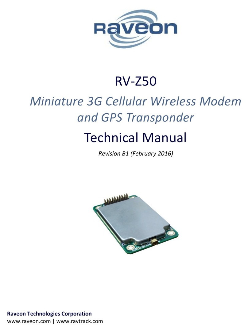
Raveon RV-Z50 User manual

RV-Z50
Miniature 3G Cellular Wireless Modem
and GPS Transponder
Quick Start Guide
Revision B1 (July 6, 2017)
Raveon Technologies Corporation
www.raveon.com | www.ravtrack.com

RV-Z50-E Quick Start
2
1Contents
2 Overview ...............................................................................................................................................4
3 Evaluation Kit ........................................................................................................................................4
4 Mechanical............................................................................................................................................5
5 Input and Output .................................................................................................................................. 5
5.1.1 LED ........................................................................................................................................5
5.1.2 Universal Wireless Radio Connector..................................................................................... 5
5.1.3 Connecting to Power............................................................................................................. 6
5.1.4 RF Antenna Connection ........................................................................................................6
5.1.5 GPS Antenna Connection......................................................................................................6
6 Operational Modes and Configuration.................................................................................................8
6.1 Carrier Data Connections..............................................................................................................8
6.2 Uplink Data (From Z50).................................................................................................................8
6.2.1 Configuring the Modem for Data Transmission.................................................................... 8
6.2.2 Data Reception......................................................................................................................9
6.3 Downlink Data (To Z50).................................................................................................................9
6.3.1 Configuring the Modem for Data Reception ........................................................................9
6.4 Communication between Z50s ..................................................................................................... 9
6.5 GPS Position Transmission............................................................................................................9
6.5.1 Idle Transmission Rate ........................................................................................................10
6.5.2 Active Transmission Rate ....................................................................................................10
6.5.3 Report Format.....................................................................................................................10
6.5.4 Local Position Information..................................................................................................10
6.5.5 Deep Sleep ..........................................................................................................................10
6.6 Data Reception............................................................................................................................10
6.6.1 GPS Position and Status ......................................................................................................10
6.7 Local NMEA data from the internal GPS.....................................................................................11
6.8 Pass-Through Mode ....................................................................................................................11
7 Command Mode .................................................................................................................................12
7.1 Command Mode Encoding and Line Format ..............................................................................12
7.2 Entering Command Mode...........................................................................................................12
7.3 Using Commands ........................................................................................................................12
7.4 Exiting Command Mode..............................................................................................................13
7.5 Configuration Commands ...........................................................................................................13
7.6 Data Communication Commands ...............................................................................................14
RV-Z50-E Quick Start
3
7.7 SIM Card......................................................................................................................................14
7.7.1 Acquiring a SIM card ...........................................................................................................14
7.7.2 Static IP vs. Dynamic IP .......................................................................................................14
7.7.3 Installing the SIM ................................................................................................................15
7.8 Factory Default Settings..............................................................................................................16
8 NOTICE ................................................................................................................................................16
8.1 Safety Training information ........................................................................................................16
8.2 Regulatory Agency Compliance Information ..............................................................................16
8.3 Warranty .....................................................................................................................................16

RV-Z50-E Quick Start
4
2Overview
The Z50 Wireless Modem is a secure, high-performance, long-range
wireless modem and GPS transponder. Three data interfaces are
available, transparent-link mode, module pass-through, and
Raveon’s WMX Wireless Packet Format. Modem operation is
virtually transparent to the user and the configuration of the
modem is done easily through the user serial port.
As a GPS transponder, configuration is as simple as setting a report
rate. Many options are available to create a customized GPS
transponder by adjusting reporting rules and detail levels of GPS reports.
For security, AES-128 encryption is used to secure your data. Its universal I/O connection makes it
interchangeable with many other Raveon wireless devices.
While easy to use out-of-the-box, the Z50 modem’s programmability makes it extremely versatile. Most
parameters may be reconfigured to optimize for specialized operations, extended range or higher data
throughput.
3Evaluation Kit
An evaluation kit may be used to test the RV-Z50-E. Contact sales@raveon.com to request your
evaluation kit. Included in the kit is a serial data cable, power cable, antenna, and adapter board. An
enclosure with an RS-232 interface completes the kit as shown below.

RV-Z50-E Quick Start
5
4Mechanical
5Input and Output
5.1.1 LED
By default, the LED on the Z50 modem module will indicate the following:
Green: Radio has received a data packet
Red: Radio is transmitting a data packet
Flashing Orange: GPS is trying to lock onto GPS or GLONASS satellite signals. (Flashing
will cease when Z50 has position lock from satellites)
Many commands modify the operation of the LED, including disabling it entirely. The ATL command can
disable the LED on the module, saving power consumption.
5.1.2 Universal Wireless Radio Connector
Raveon utilizes a universal connector configuration on many of its radio modem modules, so the Z50 is
interchangeable with dozens of other radio modems. The UWRC connector pin-out is as shown below
20- Pi n U W RC I n te r f ac e P o rt
Pin #
Function
Description
1
GND
Ground
2
VCC
DC Input. 5V (-3A version) 7-30V(-3B version)
3
CD
Carrier Detect Out.
4
TX On
Pin is High when module is transmitting. Low when off,
receiving, or sleeping.
5
Data In (TXD)
Serial transmit data input.
6
Data Out (RXD)
Serial receive data output.
7
Enable
Low to shut down the module. High to enable it.
8
Sleep
CPU Sleep input. Put in low-power fast-startup mode.
9
CTS
Clear to send output. Indicates state of internal buffers.
10
RTS
RTS input for serial flow control.
11
NC
No Connection
12
VDIG
3.3V output. Limit current draw on this power source to 50mA.
13
IOA
IO port A, USB DP
14
IOB
IO port B, USB port, DM
15
IOC
IO port C
16
STAT1
Status IO 1
17
NC
No Connection
18
STAT2
Status LED out
19
GND
System Ground
20
V-BACK
Optional Backup Battery In

RV-Z50-E Quick Start
6
The primary connector is fully pin-for-pin compatible with M8 UHF, VHF, 220MHZ modems, and V50 ISM
band radio modems.
By default, the serial port is set to 38400 baud, 8 data bits, 1 stop bit, no parity bit.
5.1.3 Connecting to Power
The Z50 is available with two DC power input options. The -3A version is designed to run off of 5V DC
input. The -3B version has an internal high-efficiency DC-DC converter allowing the unit to be powered
from 7-30 volts DC. Pin 19 must be connected to the ground or negative power supply signal. Pin 2 is the
positive DC input voltage.
5.1.4 RF Antenna Connection
The RF Antenna Connection on the Z50 is an MMCX female. A typical mating
connector, MMCX male, is a RMX-9010-1B from RF Industries.
A suitable antenna must work on the frequency bands that your cellular carrier
is using. The Z50 can operate on any of these UMTS bands: B1, B2, B5, B6, B8, or
B19. The antenna used with the Z50 must be designed to operate on all of the bands that the carrier
you are using will utilize. To comply with FCC regulations limiting both maximum RF output power and
human exposure to RF radiation, the maximum antenna gain including cable loss
If the antenna is within 1 meter of a human, must not exceed:
6.43 dBi in the cellular band
3.0 dBi in the PCS band
5.1.5 GPS Antenna Connection
If installed, the GPS Antenna Connection is a U.FL female (sometimes known as IPEX)
Common Carriers use these types of wireless technology and frequency bands:
T-Mobile (3G WCDMA) Bands B2
For AT&T Bands B2, B5

RV-Z50-E Quick Start
7
UMTS Frequency Bands
Band
Name
Low
(MHz)
High (MHz)
BW
Low
High
Spacing
B2
1900 PCS
1805
1880
75
1850
1910
80
B5
850
875
885
10
824
849
45

RV-Z50-E Quick Start
8
6Operational Modes and Configuration
6.1 Carrier Data Connections
Before a Z50 can be used the first time, it must be configured for connection to the carrier’s cellular
network. The following commands describe how to configure the Z50’s connectivity to the carrier.
ATAPN An Access Point Name (APN) may or may not be required, depending on the application.
ATAPN ATT.NET to set the APN to ATT.NET
ATAPN NULL to disable the APN feature.
ATAPU access point User Name.
ATAPU WorldRadio to set the user name to WorldRadio
ATAPU NULL to disable the user name.
ATAPP access point password.
ATAPP 12345678 to enter the password as 12345678
ATAPP NULL to disable the password.
ATCPIN NULL or set to 0000
ATCPIN 12345678 to enter the PIN as 12345678
ATCPIN NULL to disable the PIN.
6.2 Uplink Data (From Z50)
To transmit data from the Z50, send one or more bytes of data into the serial port of the modem. When
a full packet of data has been collected into the internal buffer of the modem; there is a pause in the
data per ATR3; or the maximum packet size is reached, the modem will automatically connect to the
cellular network, and send the data over the air to the carrier.
6.2.1 Configuring the Modem for Data Transmission
Configure the Hostname or Host IP address to send the data to.
ACHN command sets the host name or the host IP address. The ACHN command parameters are stored
internally in the Z50, so these parameters need only be configured one time. But they may be modified
at any time
ACHN HelloWorld.com to set the destination IP address to the host named HelloWorld.com
ACHN 123.456.789.ABC to set the destination IP address to 123.456.789.ABC
ACPN command sets the host IP port number. The ACPN command parameters are stored internally in
the Z50, so these parameters need only be configured one time. But they may be modified at any time
ACPN 3885 to set the destination port number to 3885

RV-Z50-E Quick Start
9
6.2.2 Data Reception
In order to receive data from the Z50, set up a UDP or TCP server and set that server’s hostname and
port as the destination in the Z50.
6.2.2.1 How to Set Up a Test Server
There are many ways to set up a server to receive data from a Z50. A simple linux UDP echo server to
test your Z50 can be set up with socat.
To install socat run: apt-get install socat
Once installed a udp echo server can be set up with: socat -v PIPE UDP-LISTEN:Port,fork
Where Port is the port number you wish to receive data at.
Note: Additional steps may be required for port forwarding with a firewall.
6.3 Downlink Data (To Z50)
To receive data with the Z50, the Z50 must first establish a connection with the server which it would
like to receive data from.
While the Z50 is connected all data received from the server will be sent out the serial port.
6.3.1 Configuring the Modem for Data Reception
Configure the Hostname or Host IP address to send the data to, then connect.
ACHN command sets the host name or the host IP address. The ACHN command parameters are stored
internally in the Z50, so these parameters need only be configured one time. But they may be modified
at any time
ACHN HelloWorld.com to set the destination IP address to the host named HelloWorld.com
ACHN 123.456.789.ABC to set the destination IP address to 123.456.789.ABC
ACPN command sets the host IP port number. The ACPN command parameters are stored internally in
the Z50, so these parameters need only be configured one time. But they may be modified at any time
ACPN 3885 to set the destination port number to 3885
ATDT command connects the modem to the hostname and port set by ACHN and ACPN. The hostname
and port can also be set with the ATDT command by sending the hostname and port separated by
spaces after the ATDT command.
ATDT HelloWorld.com 3385 to connect to host name HelloWorld.com at port number 3385
6.4 Communication between Z50s
Direct communication between Z50s requires that each Z50 has a static IP address. In order to obtain a
static IP address, contact your cellular carrier.
6.5 GPS Position Transmission
Position Transmission is enabled by setting either TXRATE or IDLERATE to a nonzero value.

RV-Z50-E Quick Start
10
When position transmission is enabled, the device will send its position and other status information
over-the-air automatically, per the configurations below.
6.5.1 Idle Transmission Rate
IDLERATE sets the idle reporting interval. This should be set to the longest acceptable time between
position reports. Conditions (detailed in the following sections) can cause the modem to transmit faster
than the IDLERATE. Set to 0 will disable any idle reporting.
6.5.2 Active Transmission Rate
TXRATE sets the active transmission rate. This is the rate the modem will send its position when one of
the conditions below arises, which can be enabled or disabled individually:
1. Motion
2. Distance Traveled
3. Speed
See the command section for details on how to configure these values.
6.5.3 Report Format
A number of output report formats are available, with the most common being $PRAVE, a customized
format for wireless GPS transponders. See the OUTPUT command for more detail.
6.5.4 Local Position Information
The NMEAOUT, NMEARATE and NMEAMASK commands will configure the unit to output its GPS
position locally over the user serial port.
6.5.5 Deep Sleep
6.6 Data Reception
6.6.1 GPS Position and Status
When the modem receives a position report and status from another modem, it will send this
information out the serial port, formatted in Raveon’s $PRAVE message format.
Change the position report output format with the OUTPUT x command. Enable/disable the local GPS
NMEA data with the NMEAOUT x command (0 off, 1 on)
The position/status messages that the modem is able to send out of its serial port are:
Message
Format
Description
OUTPUT x
Parameter/setting
$GPWPL
NMEA WayPoint List. This message is commonly used to
share waypoint locations among GPS units. The device can
output this message when it receives a position report from
other devices. A GPS connected to it, should put a
waypoint on its screen, and in its database, at the location
specified by the RV-M7.
OUTPUT 3
$PRAVE
Raveon Position & Satus. This message is sent out of the
device when it is operating in the GPS 2 mode. This
message is used by third-party and PC applications for
tracking location and status information.
OUTPUT 1
$GPTLL
NMEA Target Lat Long. This message is commonly sent by
OUTPUT 2

RV-Z50-E Quick Start
11
marine RADAR receivers to notify plotting devices of the
location of a RADAR target. The device can output this
message when it receives a position report from other
devices. A plotter or display connected to it that supports
the TLL message, should put an icon on its screen at the
location specified by the device. The icon name is the MYID
of the device that transmitted its position over the air.
$GPGGA
NMEA GPS Position Fix Data. This message is the standard
position message from a GPS receiver.
NMEAOUT 1
$GPGSV
NMEA Satellites in view. This message is the standard
message to indicate the number of satellites in view, and
their signal quality.
NMEAOUT 1
6.7 Local NMEA data from the internal GPS
The Z50 may be configured to output standard NMEA 0183 GPS messages from its internal GPS receiver.
For GPS tracking be configured to output their own GPS location via their serial port.
Following is a list of the NMEA messages that are available.
NMEA Message
Bit Number
(zero based)
Bit Mask
(hex format / decimal)
GGA
0
0×001 / 1
GLL
1
0×002 / 2
RMC
9
0×100 / 256
Once you set the “GPS Mode” of the radio using the GPS X command, you can change the NMEAMASK
parameter to modify with of the NMEA sentences will come out the serial port.
For example, to have only the RMC sentence come out the serial port, use the following command”
NMEAMASK 256
To have the GGA and GLL come out the serial port use this command:
NMEAMASK 3
The NMEAMASK parameter is the sum of all of the decimal values of the individual bits corresponding to
the NMEA messages.
6.8 Pass-Through Mode
Pass-Through Mode gives you direct control of the Sierra Wireless HL8548 module.
To enter Pass-Through Mode put the RV-Z50 into command mode, refer to section 5.2. Once in
command mode send the command ATPT.
To exit command mode, send the escape sequence ++++.

RV-Z50-E Quick Start
12
For operation while in Pass-Through Mode please refer to the Sierra Wireless AirPrime –HL6 and HL8
Series –AT Commands Interface Guide located at http://source.sierrawireless.com.
Note: Changing setting of the Sierra Wireless HL8548 while in Pass-Through Mode may affect the
operation of the RV-Z50 in other modes.
OK
7Command Mode
Command Mode is used to program and configure the modem. This mode is separate from data mode
and will not transmit received data over-the-air, instead executing commands detailed in this manual.
7.1 Command Mode Encoding and Line Format
In Command Mode, all characters are ASCII encoded. All output lines will use the standard network line
ending, CR+LF (ASCII 0x0D followed by ASCII 0x0A).
Inputs lines may use either CR, LF or CR+LF line endings.
7.2 Entering Command Mode
The modem may be put into a Command Mode, by entering a sequence of three plus characters (+++),
called the Entry Sequence.To keep the modem from unintentionally entering the Command Mode
because of the Entry Sequence occurring in a stream of data entering the modem, there must be a
pause in the data stream before the Entry Sequence as well as a pause afterwards. If either pause is
missing, the modem will not enter the command mode. The pause length is configurable, by default it is
500ms.
When the modem first enters the Command Mode, it will output the base model number along with the
OK sequence:
Raveon RV-Z50
OK
Once in command mode, the instructions in the following sections can be followed to continue radio
configuration.
7.3 Using Commands
To execute a command, send the command name and any parameters separated by spaces, followed by
a line ending character. For example, to use the ATAPN command to set the access point name (APN) to
1234, send:
ATAPN 1234<LF>
Some commands may output result information on lines following the command, but the output will
always terminate with either the OK sequence (introduced in the previous section) or the ERROR
sequence (ERROR<CR><LF>).
Some commands may have different results depending on the number of parameters. In general, a
command that sets a parameter(s) can read back its values by issuing the command with no parameters.
To get on-line help with a command, enter the command with a question mark at the end.
To see a list of all commands, use the HELP command.

RV-Z50-E Quick Start
13
7.4 Exiting Command Mode
To exit command mode and return to data mode, the command EXIT may be used.
Alternatively, command mode will timeout after a configurable amount of time, by default 60 seconds.
7.5 Configuration Commands
The following commands are standard Raveon commands implemented by the modem.
Command
Command Description
Parameters
Factory
Default
EXIT
Exit command mode, do not open the link connection.
ATDT
Exit command mode and open link. A parameter after the
ATDT command will be interpreted as the link hostname to
use. If there is no parameter, the default host is used, as set
by the ACHN command.
ATAT
Silence AFTER Sequence - Sets period of silence after the
command sequence characters in mS.
Range:0 –1000
(mS)
500
ATBD
Baud Rate –Sets serial com port baud rate (bps). Over-the-
air (throughput) baud rate is set with ATR2 command.
If a PC’s serial baud rate is set higher than the fixed over-the-
air baud rate of the module, hardware handshaking may be
required.
Range: 0 –7
0 = 1200 5= 38400
1 = 2400 6=57600
2 = 4800 7=115200
3 = 9600
4 = 19200
5
ATBT
Silence BEFORE Sequence –Sets period of silence before
the command sequence character in mS.
Range: 0-1000
mS
500
ATL
Enable/Disable the LEDs –1 = LEDs always off. This
reduces some power consumption. 0 = LED operate normally.
0 or 1
0
ATMK
Address Mask –Configures local and global address space.
Each digit may be a 0,1,2,3,4,5,6,7,8,9,A,B,C,D,E,or F. In
most applications, this is kept at FFFF.
Range: 0000 - FFFF
FFFF
ATMY
Unit ID –Configures the individual ID address for this unit. 1-8
bytes. Each digit may be a 0,1,2,3,4,5,6,7,8,9,A,B,C,D,E,or F.
This is the ID transmitted in GPS/localization messages.
Range: 0 –
FFFFFFFFFFFFFFF
1234
ATR3
Serial Port Time Out –The time in milliseconds for the serial
port to time out. When data is entering the serial port, and
this amount of time passes with no more data, the Z50 will
begin to transmit the data over the air.
Range: 1 - 999
20
20mS is the
default.
ATSL
Serial Number –Reads and returns a unique electronic serial
number for this unit.
Read Only
1 - 99999999999
unique
ATST
Statistics –Show the unit’s operational statistics. See
Statistics section of user manual.
None
ATVR
Firmware Version –Returns firmware version currently
loaded on the module.
Read Only, 3
characters
None
AT&F
Restore Factory –Restore the factory default values. This
command will not erase the calibration values.
None
SID
Read Set the System ID. Normally, this setting should not be
changed.
0-255
1
SHOW
Show/display an overview of the radio’s configuration.
None
-

RV-Z50-E Quick Start
14
MODEL
Read Model number. Read the model number.
None
-
CONFIG
Show Configuration. Display the settings of every parameter
in the unit. If the parameter is 1, then the help text is not
displayed, If the parameter is 2, the configuration is output in
strictly the format used to program another unit.
None, 1, 2
-
** indicates values that are calibrated in the factory and are unit-specific. If the “Radio Type” is changed, these
will need to be re-calibrated.
7.6 Data Communication Commands
The following commands are commands implemented by the Z50 modem for communications over a
cellular network.
Command
Command Description
Parameters
Factory
Default
ATAPN
Set APN
ATAPU
Set APN user name
ATAPP
Set APN password
ATCPIN
Set SIM card PIN number
ATPT
Enable pass-through mode and exit command mode.
++++
Exit pass-through mode if it was operational.
ACPR
Read/Set Link Protocol –Parameters can be one of the
following based on the desired protocol: UDP, TCP, DART
UDP
ACHN
Read/Set Hostname or IP address. Set the URL or IP
address for the link. helloworld.com or 123.45.67.89. For
DART systems, this is the hostname of the Master Gateway.
1234
ACPN
Set/read the port number on the destination host to
communicate to.
1234
7.7 SIM Card
Subscriber Identity Module card (SIM card) is a smart card that gives a cellular connected device its
customer identity. 3G and 4G devices use SIM cards. Activated by the cellular carrier, the SIM card
contains a unique ID, authentication codes, network-specific data and the customer's account ID.
7.7.1 Acquiring a SIM card
A SIM card for the Z50 may be acquired from Raveon when you purchase the Z50, or you may acquire it
from the carrier you choose or an MVNO. The Z50 is PTCRB certified and will work with any carrier or
MVNO that accepts PTCRB certified devices.
7.7.2 Static IP vs. Dynamic IP
When using a dynamic IP SIM Card in order to receive data on the Z50 the Z50 must first establish itself
with the server. In order to connect to a Z50 from a server or to connect from Z50 to Z50, the SIM card
must have a static IP. See Section 6.2 and 6.3.

RV-Z50-E Quick Start
15
7.7.3 Installing the SIM
To install the SIM card into the Z50:
1. Unlock the SIM card holder by sliding the lock towards the center.
2. Open Hinge of the SIM card holder.
3. Gently slide the SIM card into the hinging portion of the SIM card holder, it will only fit one way.
4. Close the hinge and lock the SIM card holder.

RV-Z50-E Quick Start
16
7.8 Factory Default Settings
Access Point Name (APN)........................................................internet
Access Point Username ...........................................................Null
Access Point Password ............................................................Null
Host Name...............................................................................1234
Port Number............................................................................1234
SIM Card PIN............................................................................Null
Link Protocol............................................................................UDP
Serial port ................................................................................38400 baud, N/8/1
Hardware flow control ............................................................Off
ID (ATMY).................................................................................1234
GPS Mode : 2
Serial port output message: PRAVE
Position/Status report interval: 120 seconds
Minimum movement distance to report: 30 meters
Transmission trigger inputs: 0 (digital inputs disabled)
Security KEY (KEYPHRASE): RAVEON
Proximity Alert: 0, off
I/O Change reporting: 0, off
ID Prefix: V
8NOTICE
There are no user-serviceable points inside this transceiver. All service work must be referred to your
Authorized Service Center or Raveon Technologies Service Department.
8.1 Safety Training information
Always use this radio with the antenna supplied with it, or with an antenna the meets the requirements
described in this document.
8.2 Regulatory Agency Compliance Information
PTCRB Certified. For more information, refer to the official PTCRB website www.ptcrb.com.
8.3 Warranty Raveon Limited One Year Warranty
This warranty applies to the specific product described in the literature wherein this warranty information
is included.
If within one year from date of purchase, this product fails due to a defect in material or workmanship,
Raveon Technologies, Incorporated will repair or replace it, at Raveon's sole discretion. This warranty is

RV-Z50-E Quick Start
17
extended to the original consumer purchaser only and is not transferable. The exclusive remedy for a
claim under this warranty shall be limited to the repair or replacement, at Raveon Technologies.
This warranty does not apply to: (a) product damage caused by accident, dropping or abuse in handling,
or any negligent use; (b) units which have been subject to unauthorized repair, opened, taken apart or
otherwise modified; (c) units not used in accordance with instructions; (d) damages exceeding the cost of
the product; (e) batteries; (f) the finish on any portion of the product, such as surface and/or weathering,
as this is considered normal wear and tear; (g) transit damage, initial installation costs, removal costs, or
reinstallation costs; (h) damage due to lighting, floods, fire, or earthquakes; (i) intrusion of water into or
onto the product.
RAVEON TECHNOLOGIES CORPORATION AND ITS AFFILIATES WILL DISCLAIM
LIABILITY FOR DIRECT, INDIRECT, INCIDENTAL, SPECIAL, GENERAL, OR
CONSEQUENTIAL DAMAGES. INCLUDING, BUT NOT LIMITED TO, LOSS OF REVENUE OR
PROFITS OR REVENUE ARISING OUT OF THE USE OR INABILITY TO USE ANY RAVEON
PRODUCT, EVEN IF RAVEON AND/OR ITS AFFILIATES HAS BEEN ADVISED OF THE
POSSIBILITY OF SUCH DAMAGES OR THEY ARE FORESEEABLE OR FOR CLAIMS BY ANY
THIRD PARTY. ALL IMPLIED WARRANTIES, INCLUDING THE WARRANTY OF
MERCHANTABILITY AND THE WARRANTY OF FITNESS FOR A PARTICULAR PURPOSE,
ARE HEREBY MODIFIED TO EXIST ONLY AS CONTAINED IN THIS WARRANTY.
LIMITED WARRANTY, AND SHALL BE OF THE SAME DURATION AS THE WARRANTY
PERIOD STATED ABOVE. SOME STATES DO NOT ALLOW LIMITATIONS ON THE DURATION
OF AN IMPLIED WARRANTY, SO THE ABOVE LIMITATION MAY NOT APPLY TO YOU.
This warranty gives you specific legal rights and you may also have other rights which vary from state to
state. Warranty service is available by mailing postage prepaid to:
Raveon Technologies Corporation
2320 Cousteau Court
Vista, CA 92081
To obtain warranty service, include a copy of the original sales receipt or invoice showing the date,
location, and price of purchase. Include a written description of the problem with the product, a phone
number and name of person who may be contacted regarding the problem, and the address to where the
product should be returned. Contact Support@raveon.com for any further information.
Products repaired under warranty will typically have their program memories erased and reset to factory
default settings.
Other manuals for RV-Z50
1
Table of contents
Other Raveon Modem manuals

Raveon
Raveon RF Neulink NL900PRO User manual

Raveon
Raveon RV-M8-UC series User manual

Raveon
Raveon Daisy RV-M50-E User manual

Raveon
Raveon RV-Z50 User manual

Raveon
Raveon RV-M8S User manual

Raveon
Raveon Tech Series User manual

Raveon
Raveon RV-M50 User manual

Raveon
Raveon FireLine Ethernet User manual

Raveon
Raveon RV-M7 User manual

Raveon
Raveon RV-M7 User manual