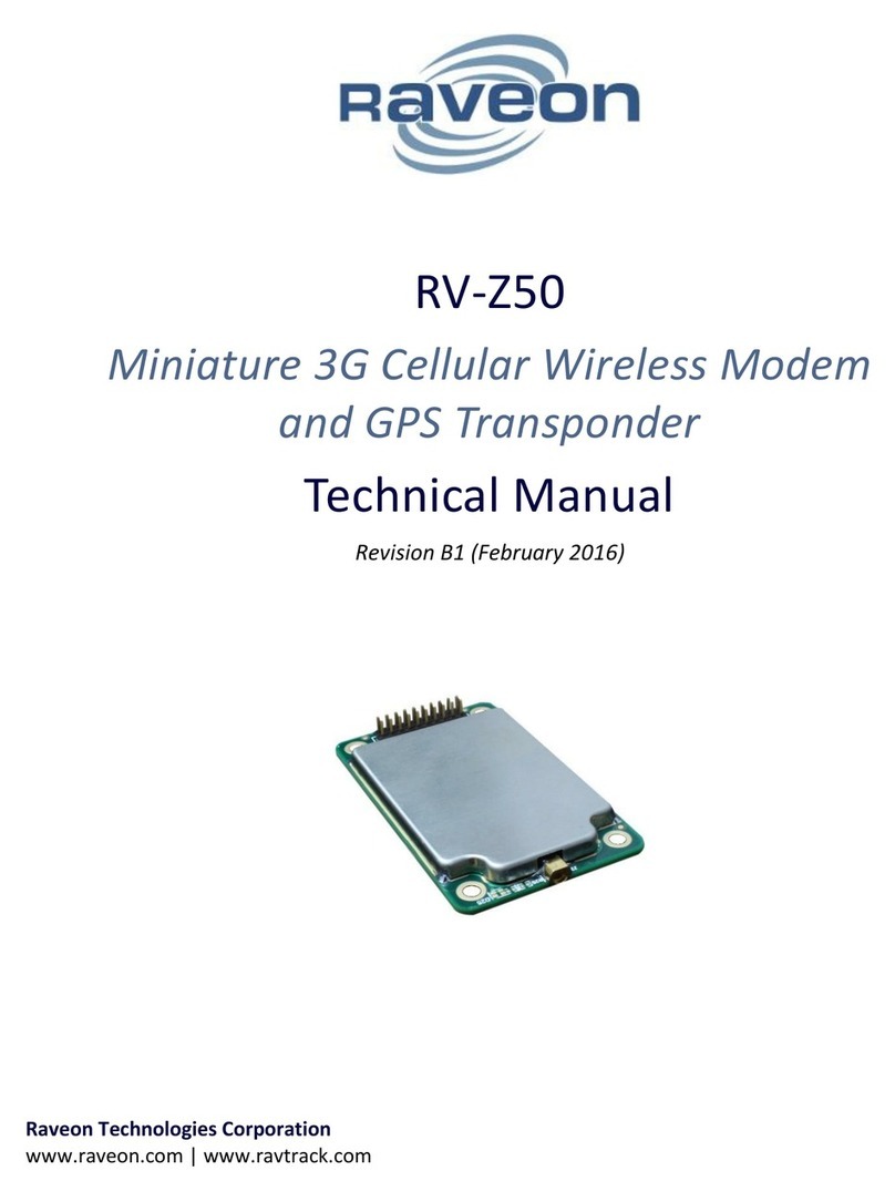
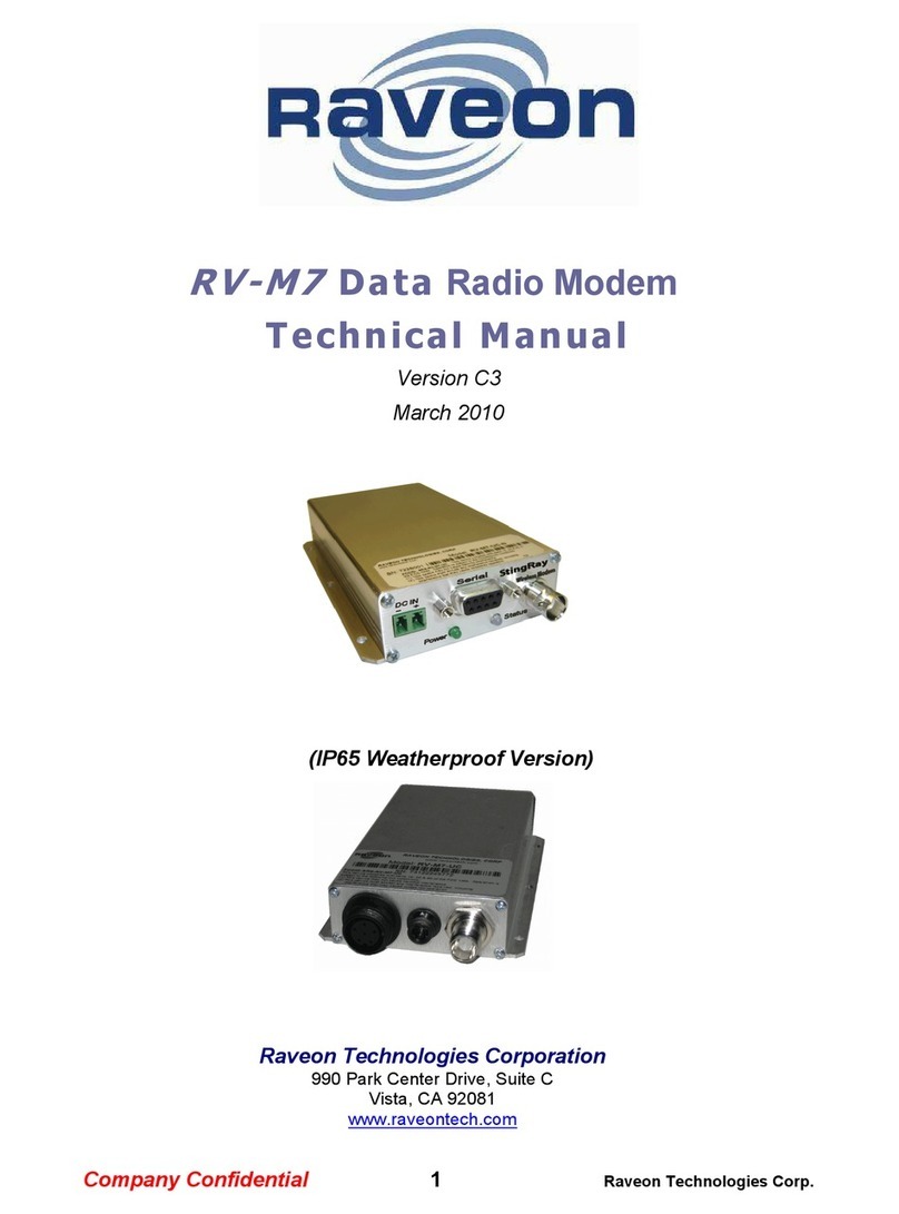
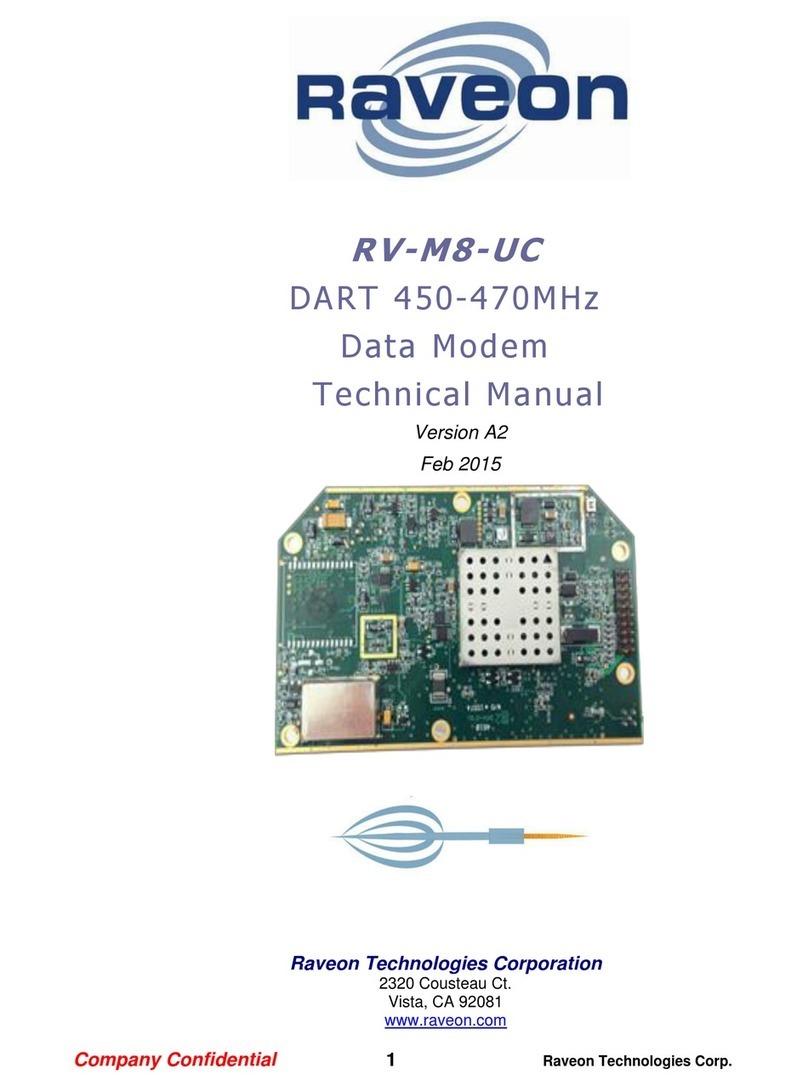
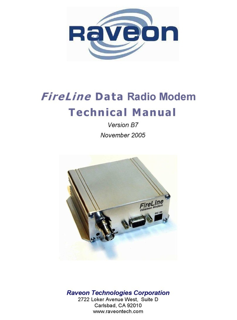
Raveon RV-M7 User manual

RV-M7
Data Radio Modem
Technical Manual
Version E2
November, 2014
IP65 "Weatherproof” Version
Raveon Technologies Corporation
www.raveon.com

RV-M7 Technical Manual
2
Table of Contents
1. General Information about the RV-M7................................................................................................ 4
1.1 Congratulations!............................................................................................................................................................ 4
1.2 NOTICE........................................................................................................................................................................... 4
1.3 Safety / Warning Information........................................................................................................................................ 4
Blasting Caps and Blasting Areas............................................................................................................................................ 4
Potentially Explosive Atmospheres ........................................................................................................................................ 5
1.4 Safety Training information:.......................................................................................................................................... 5
Antenna Installation ............................................................................................................................................................... 5
1.5 Certifications ................................................................................................................................................................. 5
1.6 FCC Compliance Information......................................................................................................................................... 6
2. Overview .............................................................................................................................................. 7
2.1 Features......................................................................................................................................................................... 7
3. Specifications........................................................................................................................................ 8
3.1 General.......................................................................................................................................................................... 8
3.2 Transmitter.................................................................................................................................................................... 8
3.3 Receiver......................................................................................................................................................................... 8
3.4 User Input and Output Signals....................................................................................................................................... 8
3.5 Model Numbers............................................................................................................................................................. 9
4. Electrical Inputs and Outputs............................................................................................................. 10
4.1 LEDs ............................................................................................................................................................................. 10
4.2 DC Power..................................................................................................................................................................... 10
4.3 RS-232/EIA232 Serial I/O Connector ........................................................................................................................... 11
4.4 -WX Weatherproof Version......................................................................................................................................... 12
Power Cord........................................................................................................................................................................... 12
4.5 RS-232 serial cable for –WX version............................................................................................................................ 14
4.6 Optional EIA-485/RS-485 Serial I/O............................................................................................................................. 15
RS-485 Connector Pin Out.................................................................................................................................................... 15
Configuring........................................................................................................................................................................... 15
Bias and Termination Resistors ............................................................................................................................................ 16
4.7 RS422/EIA-422 Serial I/O Connector ........................................................................................................................... 17
Configuring for RS-422 ......................................................................................................................................................... 17
Bias and Termination Resistors ............................................................................................................................................ 17
4.8 Low Power Mode (LPM) .............................................................................................................................................. 18
5. User Serial Port Commands................................................................................................................ 18
5.1 Overview ..................................................................................................................................................................... 18
5.2 Command Mode.......................................................................................................................................................... 18
5.3 Setting a Parameter..................................................................................................................................................... 19
5.4 Reading a Parameter ................................................................................................................................................... 20
5.5 Radio Manager ............................................................................................................................................................ 20
5.6 CONFIG Button ............................................................................................................................................................ 21
5.7 Exiting the Command Mode........................................................................................................................................ 22
5.8 Password Protection.................................................................................................................................................... 22
5.9 Command Mode Commands....................................................................................................................................... 23
5.10 Other non-AT commands ............................................................................................................................................ 28
5.11 Factory Default Settings .............................................................................................................................................. 29
6. Using the M7 Modem –Packet Mode ............................................................................................... 31
6.1 Setup ........................................................................................................................................................................... 32
6.2 Programming Channels and Frequencies .................................................................................................................... 33
6.3 Data Transmission ....................................................................................................................................................... 33
Serial Port Baud Rate............................................................................................................................................................ 33
Flow Control ......................................................................................................................................................................... 34

RV-M7 Technical Manual
3
Packet Size............................................................................................................................................................................ 34
Key-On_Data ........................................................................................................................................................................ 34
Busy-Channel Lock Out......................................................................................................................................................... 34
6.4 Addressing (Packetized Mode only) ............................................................................................................................ 34
Addressing Basics ................................................................................................................................................................. 34
Group Numbers.................................................................................................................................................................... 35
Hexadecimal Numbers ......................................................................................................................................................... 35
Setting A System-Wide Address ........................................................................................................................................... 36
Broadcast Transmissions ...................................................................................................................................................... 36
The Address Mask ................................................................................................................................................................ 36
Listen Address (Version C21 and higher firmware): ............................................................................................................. 37
Addressing Examples:........................................................................................................................................................... 37
6.5 Error Correction........................................................................................................................................................... 38
6.6 Store-and-Forward Repeating ..................................................................................................................................... 39
Automatic Repeater Configuration ...................................................................................................................................... 39
Manual Configuration of the Repeat Feature ...................................................................................................................... 39
7. Using the M7 Modem –Streaming Mode.......................................................................................... 43
7.1 Streaming Mode Operation......................................................................................................................................... 43
7.2 Baud Rate Selection..................................................................................................................................................... 43
7.3 Bit Errors...................................................................................................................................................................... 44
7.4 Carrier Detect .............................................................................................................................................................. 44
7.5 Serial Data Flow Control.............................................................................................................................................. 44
7.6 Setting the Over-The-Air Data Rate............................................................................................................................. 45
8. Installation.......................................................................................................................................... 47
9. FCC Licensing Information.................................................................................................................. 47
10. Debug Related Commands................................................................................................................. 48
11. M7 Diagnostic Provisions ................................................................................................................... 50
11.1 Overview of Diagnostics .............................................................................................................................................. 50
11.2 Reading the Diagnostic Information............................................................................................................................ 50
11.3 Status and Statistics Command ................................................................................................................................... 50
11.4 ATST Command ........................................................................................................................................................... 52
11.5 ATST2 Command ......................................................................................................................................................... 52
11.6 ATST3 Command ......................................................................................................................................................... 53
11.7 ATST4 Command ......................................................................................................................................................... 53
12. Tune-up and Alignment...................................................................................................................... 53
12.1 Periodic Calibration ..................................................................................................................................................... 53
12.2 Calibration Commands ................................................................................................................................................ 54
12.3 Center Frequency ........................................................................................................................................................ 54
12.4 TX Deviation ................................................................................................................................................................ 55
12.5 TX Modulation Balance................................................................................................................................................ 55
12.6 RX Carrier Detect......................................................................................................................................................... 55
13. SkyLine Compatibility ......................................................................................................................... 56
13.1 General........................................................................................................................................................................ 56
13.2 Configuring M7 to Communicate with a SkyLine......................................................................................................... 56
14. Antenna Information.......................................................................................................................... 56
15. Appendix A. Serial Port Hardware.................................................................................................... 58
15.1 Serial Port Data and Handshaking Signals ................................................................................................................... 58
TxD (INPUT) ......................................................................................................................................................................... 58
RxD (OUTPUT) ..................................................................................................................................................................... 58
RTS ....................................................................................................................................................................................... 58
CTS........................................................................................................................................................................................ 58
CD......................................................................................................................................................................................... 59
RV-M7 Technical Manual
4
DTR....................................................................................................................................................................................... 59
CD Output Data Framing ...................................................................................................................................................... 59
15.2 Null modem without handshaking .............................................................................................................................. 60
15.3 Compatibility issues..................................................................................................................................................... 60
15.4 Null modem with full handshaking.............................................................................................................................. 60
15.5 Compatibility issues..................................................................................................................................................... 61
16. MIMIC Mode Overview ...................................................................................................................... 61
17. Troubleshooting ................................................................................................................................. 63
Symptom: Unit will not receive ........................................................................................................................................... 63
Symptom: Unit will not transmit ......................................................................................................................................... 63
Symptom: Receive light blinks, but no data is received ...................................................................................................... 63
Symptom: Long delay before transmitting.......................................................................................................................... 64
Symptom: Cannot enter Command Mode .......................................................................................................................... 64
Symptom: Modem appears dead. ....................................................................................................................................... 64
Symptom: Repeater will not repeat. ................................................................................................................................... 64
18. Mechanical ......................................................................................................................................... 65
1. General Information about the RV-M7
1.1 Congratulations!
Congratulations on your purchase of a M7 radio modem –the most advanced radio modem of its kind
available today.
Please take a few minutes to read this manual carefully. The information presented here will allow you
to derive maximum performance from your radio modem. After reading it, keep the manual handy for
quick reference, in case questions arise later on.
1.2 NOTICE
Besides the fuse, there are no user-serviceable points inside this transceiver. All service work must be
referred to your Authorized Service Center or Raveon Technologies Service Department.
1.3 Safety / Warning Information
WARNING - DO NOT operate the RV-M7-U radio modem when bystanders are near the antenna.
For the RV-M7-UC, do not operate the radio modem when bystanders are within 2 feet (60cm) of the
antenna.
For the RV-M7-VB, do not operate the radio modem when bystanders are within 3 feet (90cm) of the
antenna.
The RV-M7 radio should be installed in safe, protected and restricted environment.
While the RV-M7 does have an internal 3A fuse, there is no internal circuit breaker. The radio should be
connected with an external circuit breaker.
Blasting Caps and Blasting Areas
To avoid possible interference with blasting operations, turn off this radio or remove the battery pack
when you are near electrical blasting caps, in a blasting area, or in areas posted: “Turn off two-way
radio.” Obey all signs and instructions.

RV-M7 Technical Manual
5
Potentially Explosive Atmospheres
Turn off your radio prior to entering any area with a potentially explosive atmosphere. Do not install
this product for use in areas with potentially explosive atmospheres. Do not remove, install, or charge
batteries in such areas. Sparks in a potentially explosive atmosphere can cause an explosion or fire
resulting in bodily injury or even death.
Note: The areas with potentially explosive atmospheres referred to above include fueling areas such as
below decks on boats, fuel or chemical transfer or storage facilities, areas where the air contains
chemicals or particles, such as grain, dust or metal powders, and any other area where you would
normally be advised to turn off your vehicle engine. Areas with potentially explosive atmospheres are
often but not always posted.
1.4 Safety Training information:
Antennas used for this transmitter must not exceed an antenna gain of 0 dBd. The radio modem must
be used in fixed vehicle-mount configurations or at fixed base-station sites. It is not intended for
portable applications.
This radio is restricted to occupational use, work related operations only where the radio operator must
have the knowledge to control the exposure conditions of its passengers and bystanders by maintaining
the minimum separation distance of following range. Failure to observe these restrictions may result in
exceeding the FCC RF exposure limits.
Antenna Installation
For rear deck trunk installation, the antenna must be located at least the following range away from rear
seat passengers and bystanders in order to comply with the FCC RF exposure requirements.
For model RV-M7-UC:
Radiated frequency and Distance
RV-M7-UC (450-480MHz 5 watts)
1.97 Feet (0.6 m)
FCC ID: SRS-RV-M7-UC
Raveon Technologies Corporation
For model RV-M7-VB
Radiated frequency and Distance
RV-M7-VB (150-174MHz 5 watts)
90cm
FCC ID: SRS-M7-VB
Raveon Technologies Corporation
For vehicular roof top installation, the antenna must be placed in the center of the roof.
1.5 Certifications
The following certifications are specific to models RV-M7-Vx:
Electromagnetic Compatibility and Radio Spectrum Matters (ERM):

RV-M7 Technical Manual
6
ETSI EN 300 113-2 V1.4.2 (09) ETSI EN 301 440-2 V1.4.1 (10)
ETSI EN 301 489-1 V1.8.1 (08) ETSI EN 50 385 (02)
ETSI EN 301 489-3 V1.4.1 (02) ETSI EN 301 489-5 V1.3.1 (02)
European Automotive EMC Directive: 2004/104/CE
Electrical Safety: EN 60950-1 :2006/A11 :2009
The following certifications are specific to models RV-M7-VB-x:
Industry Canada: 8386A-RVM7VB
1.6 FCC Compliance Information
This device complies with part 15 of the FCC Rules. Operation is subject to the following two conditions:
(1) This device may not cause harmful interference, and (2) this device must accept any interference
received, including interference that may cause undesired operation.
Changes or modifications not expressly approved by the party responsible for compliance could void the
user’s authority to operate the equipment.
NOTE: The manufacturer is not responsible for any radio or TV interference caused by unauthorized
modifications to this equipment. Such modifications could void the user’s authority to operate the
equipment.
This product also complies with FCC Part 22, 90 and Part 95 Subpart J of the FCC rules and regulations.
The Federal Communications Commission (FCC), with its action in ET Docket 93-62, has adopted a safety
standard for human exposure to Radio Frequency (RF) electromagnetic energy emitted by FCC-certified
equipment. This product meets the uncontrolled environmental limits as stated in OET-65C (01-01)
when operated in accordance with the operation guidelines described in this manual. Proper operation
of this radio device according to the instructions in this publication will result in user exposure
substantially below the FCC recommended limits.
This equipment generates, uses, and radiates radio frequency energy, and if not installed and used in
accordance with the instructions, may cause harmful interference. However, there is no guarantee that
interference will not occur. If this equipment does cause interference to radio or television reception,
which can be determined by turning the equipment off and on, the user is encouraged to correct the
interference by one of the following measures:
•Reorient or relocate the receiving antenna.
•Increase separation between the equipment and receiver.
•Connect the equipment to an outlet on a circuit different from which the receiver is connected.
•Consult the dealer or an experienced radio/TV technician.

RV-M7 Technical Manual
7
2. Overview
The M7 RF data radio is a rugged high-performance, high-speed narrow-band data modem. It contains a
receiver, a transmitter, and modem, creating an easy-to-use
transparent data radio link. The M7’s user interface is
asynchronous RS-232 data into and out of the M7 (CMOS level
optional). Modem operation is virtually transparent to the user
and the configuration of the modem is via the user serial port.
Unlike any other radio modem on the market, the M7 may be operated in either a “Packetized Mode” or
a “Streaming Real-Time Mode”. There are advantages to each approach, and your choice depends upon
how your system operates.
For privacy and network versatility, the M7 incorporates a 16 bit identification code. Its protocol also
uses a 16bit CRC to guarantee the integrity of the data. Perfect for SCADA and telemetry applications,
the M7 can be used for simple point-to-point data communication applications, or for more
sophisticated point-to-multipoint, peer-to-peer, or mesh networks.
Although the M7 is the easiest to use modem on the market, its re-programmability makes it extremely
versatile. Most parameters within the modem may be re-configured to optimize it for specialized
operations, extended range, or higher data throughput.
2.1 Features
High-speed over the air data rates.
Built-in radio transceiver with integrated modem
Easy to use. Plug-in, Turn-on, and GO. Transmit data in = Receive data out.
Lowest current draw in industry.
Wide input voltage with high-efficiency switching voltage regulator.
Integrated Packet data protocol and built-in Streaming Real-Time operation.
ARQ error correction and retransmission capability. Totally transparent to the application.
Capable of store-and-forward repeating operation.
Small sized and very rugged extruded enclosure.
16 bit addressing for up to 65,525 different unique device addresses per channel
Supports group and broadcast transmissions. Network mask allows groups of any size.
0.5-5 watts of RF output (user selectable).
Easily configured using “AT” commands
Very fast Transmit-to-Receive turnaround time.
RS-232 serial input and output. Programmable serial baud rates up to 57600.
Programmable over-the-air data rates for long-range or high-speed
Automatic key of transmitter on data.
RF carrier-detect is not required receiving. No squelch setting required.

RV-M7 Technical Manual
8
3. Specifications
3.1 General
All measurements made per TIA-603-B
Frequency: Model RV-M7-VA (Non-US Frequency; except military) ............................................. 136 - 155MHz
Model RV-M7-VB.......................................................................................................... 150 - 174MHz
Model RV-M7-UA (Non-US Frequency)........................................................................ 403 –434MHz
Model RV-M7-UB (Non-US Frequency) ........................................................................ 419 –440MHz
Model RV-M7-UC ......................................................................................................... 450 –480MHz
Model RV-M7-UD (Non-US Frequency)........................................................................ 470 –512MHz
Size.......................................................................................................... 4.60” X 2.60” X .956 (11.7cm X 6.6cm X 2.43cm)
Weight ................................................................................................................................ 6 ounces (0.17kg)
DC input voltage ............................................................................................................................................10-16V DC
Internal fuse ............................ 3A mini blade. Littlefuse part number 0297003 or Raveon part, number 1X726-3
FCC ID Model RV-M7-UC-N......................................................................................................SRS-RV-M7-UC
Model RV-M7-VB................................................................................................................SRS-M7-VB
All other models for export or OEM use
3.2 Transmitter
See Individual product data sheets for RF specifications
3.3 Receiver
See Individual product data sheets for RF specifications
3.4 User Input and Output Signals
Serial port baud rates .................................................................. 1200, 2400, 4800, 9600, 19200, 38400, 57600, 115200
Voltage levels ..................................................................................... RS-232, RS-422, and RS-485 complaint levels
Modem handshake signals .............................................................................................................RTS, CTS, DTR, DSR, CD
RF I/O .........................................................................................................................................50 ohm BNC
Power ........................................................................................................................... B+ input and Ground
Power Connector ........................................................................................Phoenix 18 36 18 9 ( Raveon P/N 1J165-3 )

RV-M7 Technical Manual
9
3.5 Model Numbers
The model number of the M7 modem identifies its operating frequency band, RF power level, and
bandwidth. The models are:
RV-M7-ab-c-oo where:
a
= The band (V=136-174MHz, U=406-512MHz)
b
= Sub band (A,B,C,…)
c
= Channel Spacing (blank=12.5kHz, W=25kHz)
oo
= Options (-GX for GPS, -WX for waterproof enclosure)
Other frequency bands, power levels, and channel spacing are available. Contact Raveon for your
specific needs.
Sub-Bands
Sub-Band
Letter
VHF (RV-M7-V…)
UHF (RV-M7-U…)
A
136-155MHz
403-434MHz
B
150-174MHz
419-440MHz
C
450-480MHz
D
470-512MHz

RV-M7 Technical Manual
10
4. Electrical Inputs and Outputs
The front panel of the M7 modem has these features:
1. RF connector
2. Power LED
3. Status LED (Receive data = green, TX = red)
4. 9-Pin Serial I/O connector
5. DC Power Jack
4.1 LEDs
The status LED indicates the current status of the radio.
Status LED (TX) This LED blinks red when the transmitter keys and is putting out RF power. It blinks
green upon the reception of data or RF carrier.
Power LED (PWR) This LED does a short blink, once every two seconds, indicating to the user that the
power to the modem is ON and the modem is working. When the modem is in the command mode, this
LED will blink on and off, once per second.
4.2 DC Power
DC power for the modem is connected to the 2-pin DC power input jack labeled DC IN. Use the supplied
cable to connect the DC power. The red wire is positive (+) and t he black wire is negative (-). Its
connection is optional, as the user may alternately apply power to Pin 9 and ground to pin 5 of the 9-pin
I/O connector.
The M7 modem is supplied with a DC power cable, Raveon part number 1C738-1.
Note: The M7 has in internal 3-amp mini-fuse (automotive type) to protect it and its power source
against reverse voltage and serious hardware failures. In the event it is blown due to a reverse voltage,
it may be replaced by removing the internal circuit board and unplugging the fuse. This must be done by
a qualified electronic technician using ESD precautions.

RV-M7 Technical Manual
11
4.3 RS-232/EIA232 Serial I/O Connector
The RS-232 9-pin serial I/O connector is a female 9-pin D-subminiature connector having the following
pins configuration. It is pinned out so that it may be plugged directly into a computer or PC’s 9-pin COM
port.
Front-view of DB-9 connector on modem (female)
Pin
Name
Dir
Function
Level / Specification
1
CD
out
Carrier detect
If enabled, indicates presence of carrier.
Logical 0 (+ voltage on RS-232) means carrier
is present. If disabled, it is asserted (0)
whenever the modem is operational, and not in
the configuration mode. It will be a 1 when the
modem is in the configuration mode. Configured
with the ATR1 setting.
2
RxD
out
Receive data
Data out of the modem.
3
TxD
in
Transmit data
Data into the modem.
4
DTR
in
Data terminal
ready
Normally ignored by the M7 modem. May
control the power-state of the modem in low-
power mode if this feature is enabled.
5
GND
Ground
connection
Signal and power ground
6
DSR
out
Data Set Ready
Normally is set to 0 when modem is powered on
and running. Modem sets to a 1 when in low-
power mode or in command mode.
7
RTS
in
Request to send
Used to stop/start the flow of data coming out of
the modem TxD pin. 0 = OK to send, 1 = don’t
send. Leave disconnected if not used.
8
CTS
out
Clear to send
Used to stop the flow of data going into the RxD
pin from the device connected to the M7. 0 =
OK to send, 1 = don’t send. If the M7 cannot
accept more data, it will negate this signal (set
to a 1).
9
Power
In/out
DC power (not
Ring signal)
User may supply the DC power to the modem
on this pin.

RV-M7 Technical Manual
12
Note: RS-232 signals use positive and negative voltages to represent digital 1s and 0s. A positive voltage is a 0, and a
negative voltage is a digital 1.
This pin-out enables the radio to be directly connected to a computer’s 9-pin serial port using a
conventional 9-pin RS-232 serial cable. To connect it to a modem, or computer peripheral that has a
serial port, a “null-modem” cable is required. See Appendix A for more information on wiring a null-
modem cable.
To configure the M7 modem for RS-232 operation, use the ATIO 0 command. RS-232 is the default
operation mode for the connector. RS-485 is a factory option. See the next section for details on the
RS-485 option.
4.4 -WX IP65-rated (“weatherproof”) Version
The –WX version of the product is functionally the same as the standard version, except it is IP65- rated
for weather resistance. It has special water-resistant connectors on it, and a sealed enclosure to keep
moisture out of the unit.
The DC Input connector is a Bulgin PX0412/03P
The RS-232 I/O connector is a Hirose HR30-6R-6P(71)
The RF I/O connection is a TNC female.
Power Cord
The DC power cord uses a Bulgin connector, part number SA3349/1. Please note diagram 2 is for use
only with WX-Z models.

RV-M7 Technical Manual
13

RV-M7 Technical Manual
14
4.5 -WX 5-Pin Circular I/O Connector Pin-Out
A) RS-232 serial cable for –WX version
The RS-232 serial cable uses at Hirose connector, part number HR30-6P-6S(71).
B) RS-422 Connector Pin-Out on –WX 5-Pin Circular Connector
If the RS422 option is installed in the M7 (-WX option), then the RS422 signals are connected to
the 5-pin water proof connector as shown below.

RV-M7 Technical Manual
15
4.6 Optional EIA-485/RS-485 Serial I/O
RS-485 Connector Pin Out
RS-485 is a two-wire connection, with the pair of wires transmitting and receiving data. With the RS-485
enabled (ATIO 2 command), the 9-pin serial I/O connector on the front of the M7 is a female 9-pin D-
subminiature connector having the following pins configuration.
Front-view of DB-9 connector on modem (female)
Pin #
Name
Direction
Function
Level / Specification
1
-
Do not connect
Do not connect this pin to anything.
2
B (-)
I/O
B
Inverting RS-485 data in line
3
Out -
out
Z
Connect to pin 2
4
A (+)
I/O
A
Non-inverting RS-485 data out line
5
GND
-
Ground
Connect to earth ground.
6
-
Do not connect
Do not connect this pin to anything.
7
Out +
out
Y
Connect to pin 4
8
9
Vin
In/Out
DC Power
DC Power in or out if unit is powered using DC
in jack.
The RS-485 differential line consists of two pins, A and B.
ATxD+/RxD+ non-inverting pin which is positive (compared to B) when the line is idle.
BTxD-/RxD- aka inverting pin which is negative (compared to A) when the line is idle.
Configuring
To configure the M7 modem for RS-485 operation, use the ATIO x command. ATIO 2 sets the serial port
for standard RS-485, full duplex. ATIO 3 sets the serial port for RS-485 simplex mode. In most cases, RS-
485 simplex is preferred (ATIO 3). In simplex RS-485 mode, the M7’s serial data receiver is internally
disabled whenever it sends a character out the serial port, so that it will not receive its own data. For
most application use the RS-485 simplex mode, ATIO 3. If you are using two M7 modems with RS-485
on both units, you must use the simplex RS-485 mode instead of the duplex RS-485 mode, or the
modems will enter an infinite loop-back condition.

RV-M7 Technical Manual
16
If you wish to run the RS-485 in full-duplex mode using two M7s, the interface must be wired with two
separate pairs of wires; A&B on one pair, and Out+ & Out- on the other pair.
The M7’s RS-485 I/O circuit uses 3.3V logic to drive the lines, and the RS-485 pins are ESD protected to
±15kV and 7kV human body model. Input current is less than 150uA. Output current when not driving
the line is less than 50uA.
Bias and Termination Resistors
RS-485 installations typically have a termination resistor across the A and B lines. For low-speed
operation (<57600 baud), this resistor is probably not necessary. If you wish to use a terminating
resistor, a value of 150 ohms should work in most applications.
These A/B pin names are all in use on various types of equipment. The RS-485 signaling specification
states that signal A is the inverting or '-' pin and signal B is the non-inverting or '+' pin. The same naming
is specified in the NMEA standards.
When an RS-485 network is in an idle state, all nodes are in listen (receive) mode. Under this
condition there are no active drivers on the network. All drivers are tri-stated. Without anything
driving the network, the state of the A and B line is unknown. If the voltage level at the receiver's A
and B inputs is less than ±200mV the logic level at the output of the receivers will be the value of the
last bit received. In order to maintain the proper idle voltage state, bias resistors must be applied to
force the data lines to the idle condition.
M7 RS-485 receivers have built-in bias resistors, offering the network a true “1/8 unit load”. In most
allocations, these internal bias resistors are sufficient, and an external bias resistor is not required.

RV-M7 Technical Manual
17
Phoenix Contact/Tyco makes a convenient DB-9 to terminal-block connector, part number 2761839.
4.7 RS422/EIA-422 Serial I/O Connector
RS-422 communications uses 4-wire differential signals. The RS422 9-pin serial I/O connector is a female
9-p D-subminiature connector having the following pins configuration.
Front-view of DB-9 connector on modem (female)
Pin #
Name
Dir
Function
Level / Specification
1
-
Do not connect
Do not connect this pin to anything.
2
B (-)
In
B
Inverting RS-422 data in line
3
Out -
out
Z
Inverting data out pin
4
A (+)
in
A
Non-inverting RS-422 data in line
5
GND
Ground
Connect to earth ground.
6
-
Do not connect
Do not connect this pin to anything.
7
Out +
out
Y
No-inverting data out
8
9
Vin
In/Out
DC Power
DC Power in or out if unit is powered using DC
in jack.
Configuring for RS-422
To configure the M7 modem for RS-422 operation, use the ATIO 4 command. You must order the RS-
422 option for this to work. The M7’s hardware is identical to the RS-485 version, with the exception of
two internal loop-back resistors.
Raveon’s RS-422 I/O circuit uses 3.3V logic to drive the lines, and the RS422 pins are ESD protected to
±15kV and 7kV human body model.
RS-422 installations typically have a termination resistor across the In and the Out lines. A value of 150
ohms should work in most applications.
Bias and Termination Resistors
M7 transceivers with the RS-422 option have receivers with built-in bias resistors, offering the
network a true “1/8 unit load”. In most allocations, these internal bias resistors are sufficient, and
an external bias resistor is not required.

RV-M7 Technical Manual
18
Serial out data comes out pins 3 and 7. Serial input data comes in via pins 4 and 8. Connect pin 5 to
earth ground.
4.8 Low Power Mode (LPM)
The M7 modem, has the ability to be put into a low power sleep mode (SM). In SM the modem draws
much less current from the DC input. In SM, the internal radio circuits in the M7 are disabled, as well as
certain current-consuming hardware circuits. The ability of the M7 to go into LPM is set with a
configuration bit, using the ATSM command.
ATSM 1 configures the M7 to monitor the DTR input line, and enter the LPM mode whenever DTR is
negated. If the DTR signal is asserted, the M7 modem will operate normally.
The ATSM 2 command forces the M7 modem into the low-power mode. In the Low Power mode, the
M7’s radio circuits are off, but it will still respond to serial commands.
The ATSM 4 command forces the M7 modem into the low-power mode, but keeps the ability to
transmit data. In the Sleep Mode 4, the M7’s radio circuits are off, but it will still respond to serial
commands. It will turn its transmitter circuits on when there is data to send, send the data, and then
power the transmitter and receiver off.
The ATSM 0 command returns the M7 modem into the normal-operating mode with the receiver and
transmitter operational.
DTR negated means it is a negative voltage. A voltage less than zero volts applied to DTR will turn the
M7 off by putting it into LPM. To assert the DTR signal (turn the modem on), the DTR line must be high
(> 3V). DTR is an input to an RS-232 transceiver IC. It is ESD protected, and is safe for voltages from –
20V to +20V input.
The factory default value for the ATSM setting is 0. When ATSM is a zero, the M7 will not ever enter the
LPM mode, and the DTR input signal is ignored.
5. User Serial Port Commands
5.1 Overview
The serial portion the RF modem is used to send and receive data over the air, as well as to configure
the RF modem. In normal operation, the user sends data into the TxD pin of the user port, and this data
is transmitted over the air. Received data from another RF modem is output to the user via the RxD pin
of the user port. This is the default operating condition of the RF modem. No special characters,
hardware control lines, or timing is required to operate the M7 modem.
There is also a “Command Mode” used to program and configure the M7. In the Command Mode, the
M7 modem accepts commands via the serial port TxD pin. The commands can be used to change
certain internal parameters of the M7 modem as well as to read-out the current configuration and
diagnostic statistics.
5.2 Command Mode
The M7 modem may be put into a “Command Mode”, by entering a sequence of three plus characters
(+++). To keep the M7 modem from unintentionally entering the Command Mode because of the +++

RV-M7 Technical Manual
19
pattern occurring in a stream of data entering the modem, there must be a pause in the data stream
before the +++ as well as a pause after the +++ is sent. If either pause is missing, the modem will not
enter the command mode.
Using serial communications software such as HypterTerminal, send the 3-character command
sequence “+++” while observing times of silence before [BT (Silence Before Sequence) Command]
and after [AT (Silence After Sequence) Command] the command characters. The default BT and AT
times are 500mS.
The default sequence for entering into AT Command Mode:
1. No characters sent for ½ a second.
2. Input three (3) plus characters (“+++”) within ½ of a second.
3. No characters sent for ½ a second.
When the M7 modem first enters the Command Mode, it sends the phrase “M7” out it serial port, and
then an “OK” sequence. The “OK” sequence is a sequence of 4 characters:
An “O”, “K”, <CR>, and <LF> characters (<CR> = ASCII 0D, <LF> = ASCII 0A)
5.3 Setting a Parameter
To set a parameter in the M7 modem, enter the Command Mode as described above. Then enter the
proper AT command, a space, the parameter, and then a carriage return. For Example, to set the
address of the M7 modem to 1234, enter the following command:
ATDT 1234 <CR>.

RV-M7 Technical Manual
20
Once a Parameter is changed, the modem will begin using the new parameter and the new
parameter is saved to non-volatile.
5.4 Reading a Parameter
To read the value of a particular setting, issue the command, with no parameter. The modem
will return the value followed by an “OK”. The modem’s OK response is:
The value in ASCII decimal format.
A <CR> <LF> (<CD> = ASCII 0D, <LF> = ASCII 0A).
An “O”, “K”, <CR>, and <LF> sequence.
For example, if the user enters the command to read the M7’s modem address and its address
was 1234, the user would issue the following command:
ATDT<cr>
and the modem will respond with:
1234 <CR> <LF>OK <CR> <LF>
To get on-line help with a command, enter the command and put a question mark in for the
parameter. For example, to see what the ATDT command is for, type ATDT ?. The modem will
respond by listing a brief description of the command. To see a list of all commands, type HELP.
5.5 Radio Manager
Radio Manager is a Windows XP/Vista software application that is used to configure Raveon's
data radio products. It is compatible with all Raveon radio models, and provides configuration
management, as well as programming assistance, diagnostic information, and a helpful "band
scope" feature.
Radio Manager features:
Supports all Raveon Radios (M3, M5, M7 and M7 GX series)
An easy to use graphical interface
Simplified editing of a radio's configuration
Configurations may be stored to a file or retrieved from a file
Intelligent parameter verification to help configure technical parameters
On-line help
Built-in terminal mode
"Auto-Detect Radio" feature searches through possible serial port settings
Band Scope feature graphically displays on and off channel signal levels
You can use Radio Manager in lieu of learning all of the M7’s commands and programming
protocol. In most situations, it is very useful for configuring the M7. There are certain very
advanced configurations that will require manual programming, but in most cases Radio Manger
will be the easiest way to setup your radio.
Other manuals for RV-M7
1
Table of contents
Other Raveon Modem manuals

Raveon
Raveon RV-Z50 User manual

Raveon
Raveon RV-M7 User manual

Raveon
Raveon RV-M50 User manual

Raveon
Raveon RV-M8-UC series User manual

Raveon
Raveon Daisy RV-M50-E User manual

Raveon
Raveon RF Neulink NL900PRO User manual

Raveon
Raveon RV-Z50 User manual

Raveon
Raveon FireLine Ethernet User manual

Raveon
Raveon Tech Series User manual

Raveon
Raveon RV-D80-EB User manual