manuals.online logo
Brands
  1. Home
  2. •
  3. Brands
  4. •
  5. RBP
  6. •
  7. Automobile Accessories
  8. •
  9. RBP RBP-FSRB1118 User manual

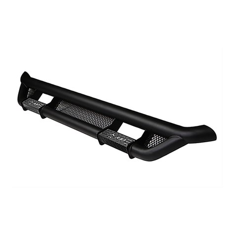
RBP RBP-FSRB1118 User manual

Page 1of 7 7/6/18 REV1 (DP)
2011 - 2018 FORD F250-550 SUPER DUTY CREW CAB, 2009 –
2018 RAM 1500-3500 CREW CAB CHASE RACK ROOF BASKET
Qty
Description
Qty
Description
1
Front Facing Logo Panel
8
12-1.75mm x 30mm Hex Bolts
1
Rear Facing Panel (tall w-light mount holes)
16
12mm x 24mm x 2.5mm Flat Washers
2
Side Panels (use left or right)
8
12mm Lock Washers
4
Cross Rails
8
12-1.75mm Hex Nuts
4
Mounting Brackets
17
10-1.50mm x 30mm Hex Bolts
4
6mm Steel spacers (17-18 Ford Model)
17
10mm x 30mm x 2.50mm Flat Washers
4
5mm Steel spacers (11-16 Ford Model)
16
10mm Lock Washers
4
2mm Rubber Seals (17-18 Ford Model)
8
8-1.25mm x 70mm Hex Bolts
4
2mm Rubber Seals (11-16 Ford Model)
20
8-1.25mm x 20mm Hex Bolts
4
2mm 6-hole Rubber Seals (all models)
16
8-1.25mm x 25mm Combo Hex Bolts
4
1mm thick Adhesive Tape (use between side
and end panels)
32
8mm x 24mm OD x 2mm Flat Washers
2
Left Rear LED Brackets
16
8mm x 16mm OD x 1.6mm Flat Washers
2
Right Rear LED Brackets
28
8mm Lock Washers
4
Side “L” LED brackets
20
8-1.25mm Hex Nuts
16
10-1.50mm Threaded Inserts
36
Decorative 8-1.25mm x 16mm Allen Head Bolts
1
10mm Threaded Insert Install Tool
36
Decorative 8-1.25mm Flange Hex Nut
1
Wrench (5mm)
Tools Required
16mm. 17mm, 18mm Sockets
Tape Measure
16mm. 17mm, 18mm Wrenches
Electric Drill
12mm, 13mm Sockets
17/32” Drill Bit
12mm, 13mm Wrenches
Dill Bit Stop
Removable Tape (masking tape)
3/8” Ratchet
Silicone Sealant
STEP 1- Carefully unwrap the (2) Side Panel Assemblies and Front and Rear Panels. Place
the parts on a clean and stable work surface. If necessary, use the packing materials to
protect the finish on the individual parts.
STEP 2- Select (1) Side Panel Assembly. Attach (1) 1mm Foam Seal to the end of the Side
Panel, (Figure 1). Attach the Front Panel to the Side Panel with (2) 12mm x 30mm Hex Bolts,
(4) 12mm Flat Washers, (2) 12mm Lock Washers and (2) 12mm Hex Nuts. Do not tighten at
this time. Repeat this Step to attach the remaining end of the Front Panel to the second Side
Panel Assembly, (Figure 2).
13000 TEMPLE AVE, CITY OF INDUSTRY, CA. 91746, 877-519-9090
RBP-
Page 2of 7 7/6/18 REV1 (DP)
STEP 3- Repeat Step 2 to attach the Rear Panel Assembly to the (2) Side Panels. This
completes the four sides to the outer Basket.
STEP 4- Select (1) Cross Brace. Attach the Cross Brace to the front mounting pads on the
left and right Side Panels with (4) 8mm Combo Bolts, (Figure 2). Do not tighten at this time.
Repeat to install the remaining (3) Cross Braces.
STEP 5- Place the Basket assembly on a clean, flat surface. Measure across the Basket,
corner to corner to make sure the Basket is square and straight. Adjust as necessary and
fully tighten all hardware.
STEP 6- Select (1) Mounting Bracket Assembly and (1) 6-slot Rubber Spacer, (Figure 3).
Attach the Rubber Spacer to the bottom of the Mount Assembly. Repeat this Step for the
remaining (3) Mounting Bracket Assemblies.
STEP 7- Locate the mounting point toward the front of the Side Panel. Attach (1) Mount
Assembly to the lowest (2) slots in the mounting point with (2) 8mm x 70mm Hex Bolts, (4)
8mm Flat Washers, (2) 8mm Lock Washers and (2) 8mm Hex Nuts, (Figure 3). IMPORTANT:
Mounting point on Side Panel features multiple slots to adjust the final installed height of the
Basket Assembly. Attach the Bracket Assembly to the lower slots to start then lower Basket
to desired height to clear roof when fully loaded. Repeat this Step to install the remaining (3)
Bracket assemblies. NOTE: Attach all Mounting Brackets to the same sets of slots at each
mounting point. Snug but do not tighten hardware at this time.
STEP 8- With assistance, carefully place the Basket assembly onto the roof of the vehicle
with Brackets flat against roof. VERY IMPORTANT: Basket assembly is heavy, cover all
mounting locations on roof of vehicle with a layer of removable tape (masking tape for
example) to prevent damage to the finish of the vehicle, (Figure 4). Line up Basket assembly
with vehicle as desired.
STEP 9- Determine the correct mounting method for your model/year, (Figure 5).
2011-16 Ford Super Duty –
1. Select (1) Narrow Spacer (1” wide) and (1) matching Rubber Seal. Apply adhesive backed
Seal to Spacer, (Figure 6). NOTE: Slots are closer together on the Narrow Spacer than the
1-1/2” wide spacer designed for 17-18 models.
2. Lift up driver/left front corner of Basket assembly. Slide (1) Spacer with Seal into channel
in roof and under Bracket assembly, (Figures 6 & 7). Line up slots in Spacer with Bracket
assembly. Repeat this Step to install remaining (3) Spacers.
3. Make sure Basket assembly is in the desired position and centered on the vehicle. Mark
center and inner slot locations of each Bracket assembly onto the roof of the vehicle,
(Figure 8). Do not mark the (2) outer slots, these mounting holes will not be utilized.
4. Temporarily remove the Basket assembly. Skip to Step 10 to continue installation.
2017-18 Ford Super Duty –
1. Select (1) Wide Spacer (1-1/2” wide) and (1) matching Rubber Seal, (Figure 9). Apply Seal
to Spacer. NOTE: Slots are farther apart on the Wide Spacer than the 1” wide spacer
designed for 11-16 models.
13000 TEMPLE AVE, CITY OF INDUSTRY, CA. 91746, 877-519-9090
Page 3of 7 7/6/18 REV1 (DP)
2. Lift up driver/left front corner of Basket assembly. Slide (1) Spacer with Seal into channel
in roof and under Bracket assembly, (Figures 9 & 10). Line up slots in Spacer with Bracket
assembly. Repeat this Step to install remaining (3) Spacers.
3. Make sure Basket assembly is in the desired position and centered on the vehicle. Mark
inner and outer slot locations of each Bracket assembly onto the roof of the vehicle,
(Figure 7). Do not mark the (2) center slots, these mounting holes will not be utilized.
4. Temporarily remove the Basket assembly. Skip to Step 10 to continue installation.
2009-18 Ram 1500, 2010-18 Ram 2500-3500 –
1. Follow previous Steps to mark the Bracket locations for drilling. NOTE: Use inner and
outer slots in Bracket. Spacers are not required for Ram models, (Figures 5, 9 & 14).
Brackets will attach flat against roof.
STEP 10- Move to the driver/left front mounting location. Use a 17/32” drill bit to drill the (4)
mounting holes in the top of the cab. VERY IMPORTANT: Depending on model/vehicle, it may
be necessary to remove or lower the headliner before drilling. Take precautions to avoid
damaging any electrical systems attached to or located between the roof and the headliner.
Use of a drill stop is highly recommended to avoid damaging the headliner.
STEP 11- Once holes have been drilled, select (1) 10mm Threaded Insert, (1) Insert Tool, (1)
10mm Flat Washer and (1) 10mm Hex Bolt, (Figure 11). Insert (1) Bolt with Flat Washer
through Tool. Thread (1) Insert onto Bolt until hand-tight. Push Insert assembly into drilled
hole. Insert should fit snug, lightly tap insert into hole if necessary. Firmly hold handle on tool
tight against rood and tighten hex bolt. Continue to tighten hex bolt to collapse/expand insert
into hole. Tighten hex bolt until threads on insert are pulled up close to top surface of insert,
(Figure 12). Do not overtighten insert or insert may become damaged. Repeat this Step for
all insert installations. Remove masking tape from roof. Apply Silicone Sealant (not included)
around all inserts.
STEP 12- Once all inserts have been installed, with assistance, place Spacers (Ford models
only) and Basket Assembly onto vehicle. NOTE: Spacers not required on Ram models. Attach
Basket assembly to Inserts with the included (16) 10mm Hex Bolts, (16) 10mm Lock Washers
and (16) 10mm Flat Washers, (Figures 13—15). Apply a bead of Silicone Sealant (not
included) around all Hex Bolts attaching Brackets to roof. Do not tighten at this time.
STEP 13- Line up the Basket assembly with the sides of the cab. Make sure the assembly is
straight and square and tighten all hardware. Do periodic inspections to the installation to
make sure that all hardware is secure and tight.
STEP 14-Light Brackets have been included to install (2) rear facing bar style LED lights,
(light installation optional-lights available separately). Attach (2) Left and (2) Right facing
Light Brackets to rear panel with the included (12) 8mm Hex Bolts, (20) 8mm x 24mm Flat
Washers, (12) 8mm Lock Washers and (8) 8mm Hex Nuts, (Figure 16). NOTE: LED Light
Brackets cannot be installed on models with bed mounted Chase Rack
STEP 15- “L” Brackets have been included to attach bar style LED lights to the Side Panels,
(light installation optional-lights available separately). Attach the “L” Brackets to the bottom
of the mounting tabs along Side Panel with the included (2) 8mm Hex Bolts, (4) 8mm Flat
Washers, (2) 8mm Lock Washers and (2) 8mm Hex Nuts, (Figure 17).
13000 TEMPLE AVE, CITY OF INDUSTRY, CA. 91746, 877-519-9090
Page 4of 7 7/6/18 REV1 (DP)
STEP 16- Install all (36) Decorative 8mm x 16mm Button Head Bolts and 8mm Flange Nuts at
this time if desired, (Figure 18).
13000 TEMPLE AVE, CITY OF INDUSTRY, CA. 91746, 877-519-9090
(Fig 1) Attach Side Panel to Rear
Panel (Driver/left side illustrated)
Front
(Fig 2) Cross Brace installed
(Fig 3) Attach Bracket with Seal to
lower mounting slots in Side Panel
Rear
Rear
Foam Seal
(2) 12mm x 30mm Hex Bolts
(4) 12mm Flat Washers
(2) 12mm Lock Washers
(2) 12mm Hex Nuts
(2) 8mm Combo Bolts
(2) 8mm x 70mm Hex Bolts
(4) 8mm x 16mm Small Flat Washers
(2) 8mm Lock Washers
(2) 8mm Hex Nuts
(Fig 4) Apply removable tape (masking tape for
example) to all mounting locations to prevent
damage to the finish (11-16 model pictured)
Attach Rubber Seal to bottom
of Bracket assembly
Page 5of 7 7/6/18 REV1 (DP)
13000 TEMPLE AVE, CITY OF INDUSTRY, CA. 91746, 877-519-9090
(Fig 8) Trace Bracket slot locations onto
removable tape (11-16 Ford model pictured)
(Fig 7) 11-16 Ford models, slide Spacer into
channel in roof and under center slots in Bracket
(arrow). Spacer not required for Ram models
(Fig 9) 17-18 Ford model illustrated
17-18 Ford models, apply Rubber Seal to
Wide Spacer. Place Spacer with Rubber Seal
down against roof, into channel in roof and
under inner slots in Bracket (See Fig 9 & 10)
(Fig 6) 11-16 Ford models, apply Rubber Seal
to Narrow Spacer. Place Spacer with Rubber
Seal down against roof, into channel in roof
and under center slots in Bracket (See Fig 6)
17-18 Ford
11-16 Ford
09-18 Ram
(Fig 5) Determine best slots to use for make &
model. Illustration provided for example only
Page 6of 7 7/6/18 REV1 (DP)
13000 TEMPLE AVE, CITY OF INDUSTRY, CA. 91746, 877-519-9090
Rear
(Fig 12) Example of Threaded
Insert fully installed
(4) 10mm Hex Bolts
(4) 10mm Lock Washers
(4) 10mm Flat Washers
(Fig 10) 17-18 Ford models, slide Spacer into
channel in roof and under inner slots in Bracket
(arrow). Spacer not required for Ram models
(Fig 14) 17-18 Ford models, attach Bracket to Spacer
and Threaded Inserts in roof Bracket (See Fig 9)
(Fig 13) 11-16 Ford models, attach Bracket to Spacer
and Threaded Inserts in roof Bracket (See Fig 6)
Rear
(4) 10mm Hex Bolts
(4) 10mm Lock Washers
(4) 10mm Flat Washers
Side Panel illustrated
“open”to show Bracket
installation only
Side Panel illustrated “open”to
show Bracket installation only
10mm Insert Tool
(Fig 11) Assemble Tool
and Threaded Insert
10mm
Threaded
Insert
10mm Hex Bolt
10mm Flat Washer
Page 7of 7 7/6/18 REV1 (DP)
13000 TEMPLE AVE, CITY OF INDUSTRY, CA. 91746, 877-519-9090
(Fig 17) Attach Led “L” Brackets to bottom of
mounting tabs along Side Panel. Attach light (not
included) to Light Brackets (install is optional)
(Fig 18) Install included (36) Decorative Button
Head Bolts if desired (installation optional)
8mm x 20mm Hex Bolt
8mm Lock Washer
8mm Flat Washer
8mm x 20mm Hex Bolt
(2) 8mm Flat Washers
8mm Flat Washer
8mm Hex Nut
“L” Light Bracket
Rear
(Fig 16) Attach (1) Left and (1) Right Light
Bracket to rear panel (optional). NOTE:
Do not install light brackets on models
with bed mounted Chase Rack
Rear
(Fig 15) 09-18 Ram models, attach Bracket
directly to Threaded Inserts in roof.
Spacers are not required for Ram models
(4) 10mm Hex Bolts
(4) 10mm Lock Washers
(4) 10mm Flat Washers
Side Panel illustrated “open” to
show Bracket installation only

Other RBP Automobile Accessories manuals

RBP STEALTH POWER RBP-216-SP User manual

RBP

RBP STEALTH POWER RBP-216-SP User manual

RBP RBP-1109B-RX3 User manual

RBP

RBP RBP-1109B-RX3 User manual

RBP RBP-510-RX7 User manual

RBP

RBP RBP-510-RX7 User manual

RBP RBP-1306B-RX3 User manual

RBP

RBP RBP-1306B-RX3 User manual

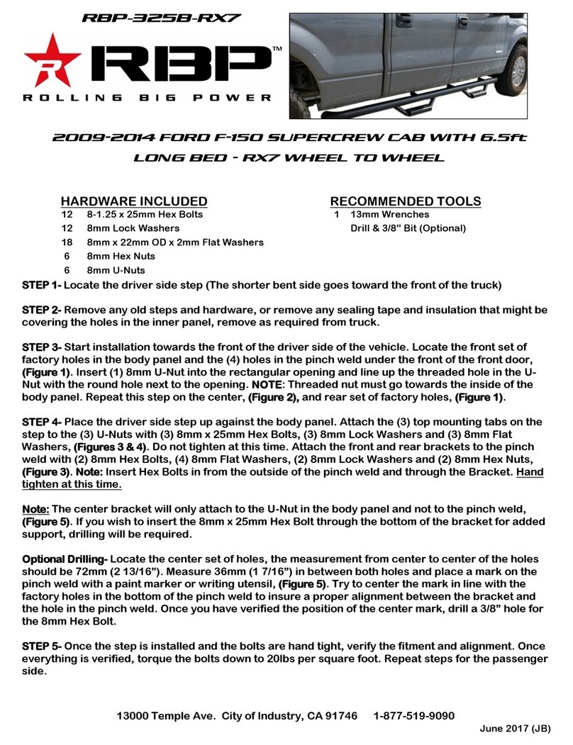
RBP RBP-325B-RX7 User manual

RBP

RBP RBP-325B-RX7 User manual

RBP RBP-1414B-RX3 User manual

RBP

RBP RBP-1414B-RX3 User manual

RBP RBP-1308B-RX3 User manual

RBP

RBP RBP-1308B-RX3 User manual

RBP STEALTH POWER RBP-215-SP User manual

RBP

RBP STEALTH POWER RBP-215-SP User manual

RBP Stealth Power RBP-510-SP User manual

RBP

RBP Stealth Power RBP-510-SP User manual

RBP RBP-414B-RX7 User manual

RBP

RBP RBP-414B-RX7 User manual

RBP RX3 Series User manual

RBP

RBP RX3 Series User manual

RBP RBP-1510B-RX3 User manual

RBP

RBP RBP-1510B-RX3 User manual

RBP RBP-1509B-RX3 User manual

RBP

RBP RBP-1509B-RX3 User manual

RBP STEALTH POWER RBP-217-SP User manual

RBP

RBP STEALTH POWER RBP-217-SP User manual

RBP RX-3 STEP BARS User manual

RBP

RBP RX-3 STEP BARS User manual

RBP RBP-1324B-RX3 User manual

RBP

RBP RBP-1324B-RX3 User manual

RBP Pro-Series Rock Rail User manual

RBP

RBP Pro-Series Rock Rail User manual

Popular Automobile Accessories manuals by other brands

Metra Electronics 99-6507 installation instructions

Metra Electronics

Metra Electronics 99-6507 installation instructions

Great day MIGHTY-LITE REAR RACK Instructions for installation and use

Great day

Great day MIGHTY-LITE REAR RACK Instructions for installation and use

ATI Technologies ePod installation manual

ATI Technologies

ATI Technologies ePod installation manual

GARO Wallbox GLB Assembly instructions/use and care manual

GARO

GARO Wallbox GLB Assembly instructions/use and care manual

HornBlasters NATHAN AIRCHIME installation manual

HornBlasters

HornBlasters NATHAN AIRCHIME installation manual

Simple ISMGM510E instruction manual

Simple

Simple ISMGM510E instruction manual

Nokia CK-100 Connection guide

Nokia

Nokia CK-100 Connection guide

STO N SHO SNS 143 Installation procedures

STO N SHO

STO N SHO SNS 143 Installation procedures

STO N SHO SNS 33 Installation procedures

STO N SHO

STO N SHO SNS 33 Installation procedures

thermal-vision IR313GT Guide to installing

thermal-vision

thermal-vision IR313GT Guide to installing

TRP X-Cover Use and care

TRP

TRP X-Cover Use and care

Fabbri Bici OK 3 Camper Top Installation and use instructions

Fabbri

Fabbri Bici OK 3 Camper Top Installation and use instructions

Volkswagen 2K3 017 221 FITTING INSTRUCTION

Volkswagen

Volkswagen 2K3 017 221 FITTING INSTRUCTION

Beeper AVANT User& installer's manual

Beeper

Beeper AVANT User& installer's manual

Torklift D3102 installation instructions

Torklift

Torklift D3102 installation instructions

Firstech FTI-NSP2 Vehicle Coverage & Preparation Notes

Firstech

Firstech FTI-NSP2 Vehicle Coverage & Preparation Notes

Go Rhino GRH-4412B instructions

Go Rhino

Go Rhino GRH-4412B instructions

Safe Fleet PRIME DESIGN AAL-8011 manual

Safe Fleet

Safe Fleet PRIME DESIGN AAL-8011 manual

manuals.online logo
manuals.online logoBrands
  • About & Mission
  • Contact us
  • Privacy Policy
  • Terms and Conditions

Copyright 2025 Manuals.Online. All Rights Reserved.