manuals.online logo
Brands
  1. Home
  2. •
  3. Brands
  4. •
  5. RBP
  6. •
  7. Automobile Accessories
  8. •
  9. RBP STEALTH POWER RBP-217-SP User manual

RBP STEALTH POWER RBP-217-SP User manual

Other RBP Automobile Accessories manuals

RBP RX-3 STEP BARS User manual

RBP

RBP RX-3 STEP BARS User manual

RBP RBP-1509B-RX3 User manual

RBP

RBP RBP-1509B-RX3 User manual

RBP RBP-1109B-RX3 User manual

RBP

RBP RBP-1109B-RX3 User manual

RBP RX3 Series User manual

RBP

RBP RX3 Series User manual

RBP RBP-FSRB1118 User manual

RBP

RBP RBP-FSRB1118 User manual

RBP RBP-1414B-RX3 User manual

RBP

RBP RBP-1414B-RX3 User manual

RBP RBP-1308B-RX3 User manual

RBP

RBP RBP-1308B-RX3 User manual

RBP STEALTH POWER RBP-215-SP User manual

RBP

RBP STEALTH POWER RBP-215-SP User manual

RBP RBP-414B-RX7 User manual

RBP

RBP RBP-414B-RX7 User manual

RBP RBP-1324B-RX3 User manual

RBP

RBP RBP-1324B-RX3 User manual

RBP RBP-510-RX7 User manual

RBP

RBP RBP-510-RX7 User manual

RBP RBP-325B-RX7 User manual

RBP

RBP RBP-325B-RX7 User manual

RBP RBP-1306B-RX3 User manual

RBP

RBP RBP-1306B-RX3 User manual

RBP RBP-1510B-RX3 User manual

RBP

RBP RBP-1510B-RX3 User manual

RBP Stealth Power RBP-510-SP User manual

RBP

RBP Stealth Power RBP-510-SP User manual

RBP Pro-Series Rock Rail User manual

RBP

RBP Pro-Series Rock Rail User manual

RBP STEALTH POWER RBP-216-SP User manual

RBP

RBP STEALTH POWER RBP-216-SP User manual

Popular Automobile Accessories manuals by other brands

Magneti Marelli AC161 Installation instruction

Magneti Marelli

Magneti Marelli AC161 Installation instruction

FDI uEZ GUI Start here

FDI

FDI uEZ GUI Start here

JCROffroad JT Install instructions

JCROffroad

JCROffroad JT Install instructions

Rostra VOXXElectronics 250-1930 owner's guide

Rostra

Rostra VOXXElectronics 250-1930 owner's guide

TOP VEHICLE TECH GR3FORD5 installation manual

TOP VEHICLE TECH

TOP VEHICLE TECH GR3FORD5 installation manual

Safe Fleet PRIME DESIGN AR-2000-BLK manual

Safe Fleet

Safe Fleet PRIME DESIGN AR-2000-BLK manual

Skoda Fabia Combi 5J Fitting instructions

Skoda

Skoda Fabia Combi 5J Fitting instructions

Camcar 40077 Al Mounting instructions

Camcar

Camcar 40077 Al Mounting instructions

Camcar 40089 AL Mounting instructions

Camcar

Camcar 40089 AL Mounting instructions

Impac Tradesman 2000 installation manual

Impac

Impac Tradesman 2000 installation manual

DVB OFFROAD BRSB-01 installation manual

DVB

DVB OFFROAD BRSB-01 installation manual

Safari Snorkel SS385HF installation guide

Safari Snorkel

Safari Snorkel SS385HF installation guide

ULTIMATE SPEED 279746 Assembly and Safety Advice

ULTIMATE SPEED

ULTIMATE SPEED 279746 Assembly and Safety Advice

SSV Works DF-F65 manual

SSV Works

SSV Works DF-F65 manual

ULTIMATE SPEED CARBON Assembly and Safety Advice

ULTIMATE SPEED

ULTIMATE SPEED CARBON Assembly and Safety Advice

Witter F174 Fitting instructions

Witter

Witter F174 Fitting instructions

WeatherTech No-Drill installation instructions

WeatherTech

WeatherTech No-Drill installation instructions

TAUBENREUTHER 1-336050 Installation instruction

TAUBENREUTHER

TAUBENREUTHER 1-336050 Installation instruction

manuals.online logo
manuals.online logoBrands
  • About & Mission
  • Contact us
  • Privacy Policy
  • Terms and Conditions

Copyright 2025 Manuals.Online. All Rights Reserved.

INSTALLATION COVERS
PART# RBP-217-SP
FOR APPLICATIONS:
2010-2018 RAM 2500/3500/4500/5500 CREW CAB
INSTALLATION GUIDE
2WWW.ROLLINGBIGPOWER.COM
Your Complete Satisfaction is Our Number One Goal at Rolling Big Power, your
satisfaction is why we’re in business. If for any reason your experience with our
product was anything less than satisfactory, please reach out to us. We’d love to
have the opportunity to provide the product experience and service you deserve.
APPLICATIONS:
2013-2018 RAM 2500/3500/4500/5500 CREW CAB
TOOLS REQUIRED
•5 MM ALLEN WRENCH
•13 MM SOCKET AND WRENCH
•10 MM COMBINATION WRENCH
•ELECTRIC DRILL
•10 MM NUT DRIVER TIP
•RAZOR BLADE
•RTV SILICONE
•50/50 MIX OF ISOPROPYL ALCOHOL
AND WATER
•1” WIDE MASKING TAPE
•MEASURING TAPE
• TORQUE WRENCH
For Installation Instruction videos visit our YouTube page at:
https://www.youtube.com/user/rollingbigpowertv
STOP. DO NOT RETURN TO THE STORE. WE CAN HELP. QUESTIONS OR PROBLEMS, OUR
TEAM OF PROFESSIONALS ARE HERE TO HELP.
CALL TOLL FREE 1-877-519-9090, MON-FRI: 8:00AM - 5:00PM PST
3
1-877-519-9090
CONTENTS
ENGLISH
Product Technical Specifications 04
Product Packing List 05
Installation 07
Warranty Information 14
4WWW.ROLLINGBIGPOWER.COM
PRODUCT TECHNICAL SPECIFICATIONS
Rated Voltage: 12V
Load Rating: 600 lbs per side
Gross Weight: 55 lbs
Horizontal Extension: 6.4”
(Horizontal distance between the edge of power board and the vehicle door when the
board extends)
Step Height: 12.4”
(Vertical height difference between the edge of power board and the vehicle door while
board extending.)
WARNING: Keep a minimum of 10” safe distance while the Stealth Power™Running
Board is operating to avoid any personal injury or damage to the running boards.
Stealth Power™Running Boards are not designed to provide vehicle body protection.
Components can be damaged by hard impact or contact with foreign objects.
6.4”
12.4”
5
1-877-519-9090
Stealth Power™Running Board Parts List
Please verify that all listed components were included in your package. If
not, please call our team at 877-519-9090 for assistance.
Left Front Motor Linkage 20×1
Left Rear Motor Linkage 20×1
Right Front Motor Linkage 20×1
Right Rear Motor Linkage 20×1
Hexagon Flange Bolt ×8
20A Fuse×2
LED Lamp Module×4
Wired Magnetic Induction
Module ×2
Magnet ×4
Hexagon Flange Bolt ×1
Hexagon Flange Bolt ×8Connecting Bracket 10×5
(Two of them are in reserve.)
Socket Cap Screw ×8
Controller mounting bracket
6WWW.ROLLINGBIGPOWER.COM
PRODUCT PACKING LIST
Notice: As shown in the picture, there is a four-
conductor plug, a six-conductor plug, a black two-
conductor plug, and a red two-conductor plug.
Controller Assembly
Motor
Motor
Motor
Motor
LED lights
LED lights
LED lights
LED lights
High Temperature
Protective Sleeve
Brown, door trigger
White, door trigger
Black 12V -,
Red 12V+
Disable switch
7
1-877-519-9090
Step 1: Disconnect the battery. Begin with the negative battery terminal,
followed by the positive terminal.
Step 2:Inspect the front Driver side and rear Driver side motor mounting
points on the truck. If your truck is equipped with threaded inserts as
shown, skip to Step 5.
Step 3: Holes that do not have factory threaded inserts will require the
threaded nut bracket that is included in this kit. To install it, feed the
bracket through the slot and let it hang from the small tab as shown.
Hang Tab
Installation Position
FRONT
INSTALLATION INSTRUCTIONS
Step 1
Step 4
Step 3
Rear Driver
Side Motor
Mounting point
Front Driver
Side Motor
Mounting point
Step 4: Install the rear Driver side motor using two M6 flange bolts to
fasten the motor to the pinch seam and two M8 flange bolts to fasten
the motor to the threaded nut bracket. Hold the bracket by the hang tab
to avoid it falling into the rocker panel. The hardware should be hand
tightened only until snug. This will allow the motor assembly to move
and align easier when installing the running board.
8WWW.ROLLINGBIGPOWER.COM
Step 5: Install the front Driver side motor using two M6 flange bolts to fasten the motor to the pinch seam and two M8
flange bolts to fasten the motor to the threaded nut bracket. Hold the bracket by the hang tab to avoid it falling into the
rocker panel. The hardware should be hand tightened only until snug. This will allow the motor assembly to move and
align easier when installing the running board.
Step 6: Install the Driver Side running board.
6a. Begin by propping up the running board on the front and rear motor assembly bases.
6b. Next align the sliding T-Nut assemblies on the running board with the slots on the front and rear motor bases.
6c. Once the T-nuts are aligned, rotate the running board so that the T-nuts drop into the slots on the base of the arms.
6d. Secure the running board to the arms using the M6 x 25 socket head cap screws. Using a torque wrench, tighten to 9 ft-lbs.
INSTALLATION INSTRUCTIONS
Step 5A Step 5B
Step 6A
Step 6C
Step 6B
Step 6D
9
1-877-519-9090
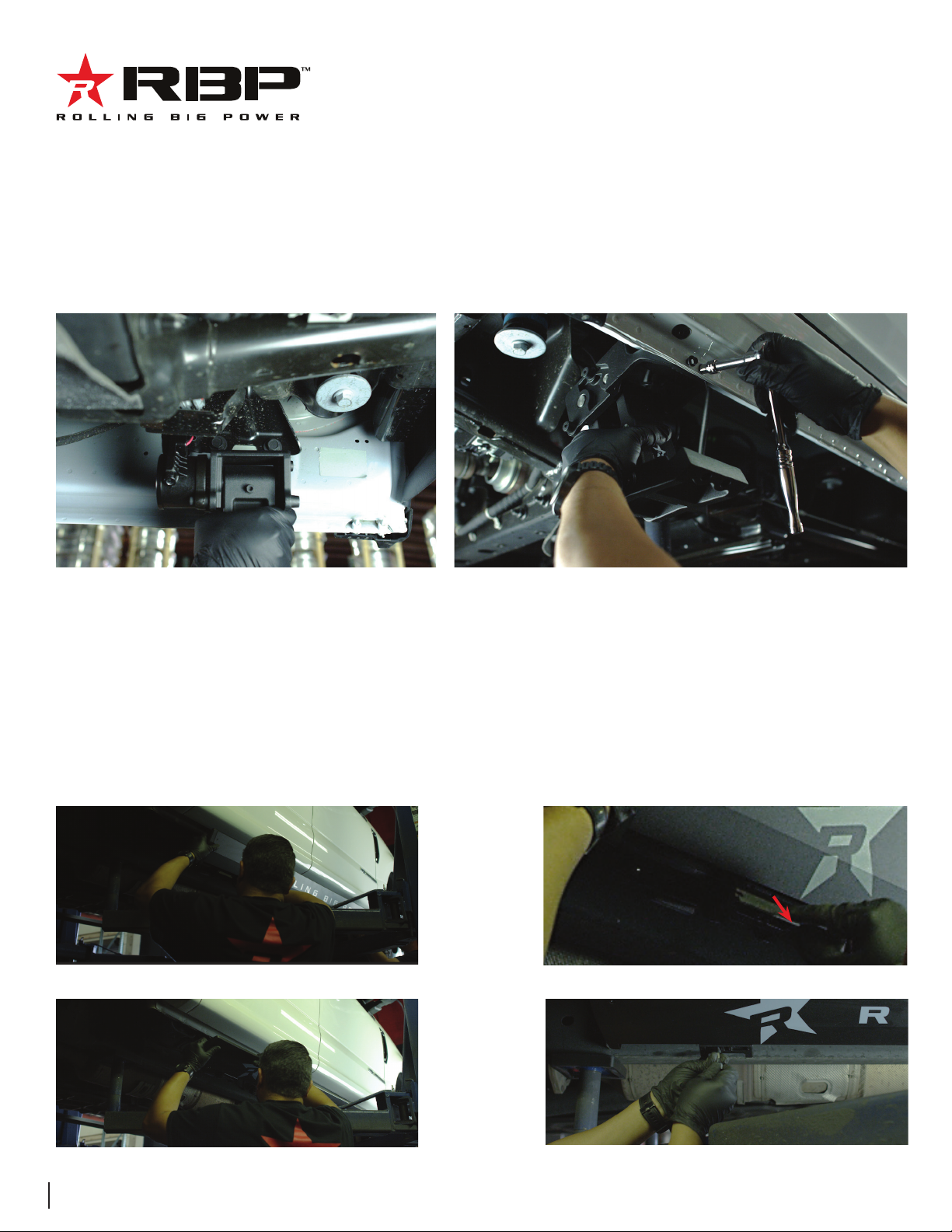
Step 7: Now that the running board is installed, go back and tighten the hardware on the Driver Side front and rear motor
assemblies. Using a torque wrench, tighten the mounting hardware to 18 ft-lbs.
Step 8: Repeat steps 2-7 to install the motor linkage assemblies and running board on the Passenger Side.
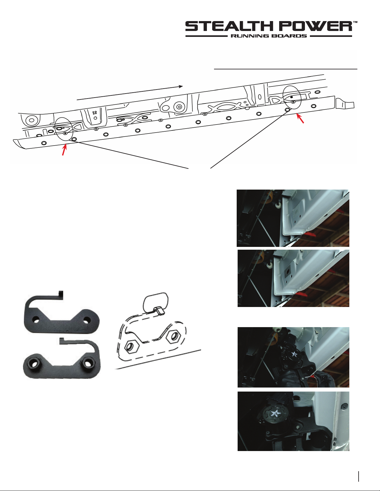
Step 9: Locate factory step mounting hole pattern just below the
middle body mount on the driver side of the truck. Peel the tape
covering the large slot. Feed the threaded bracket through the slot
and let it hang from the small tab as shown.
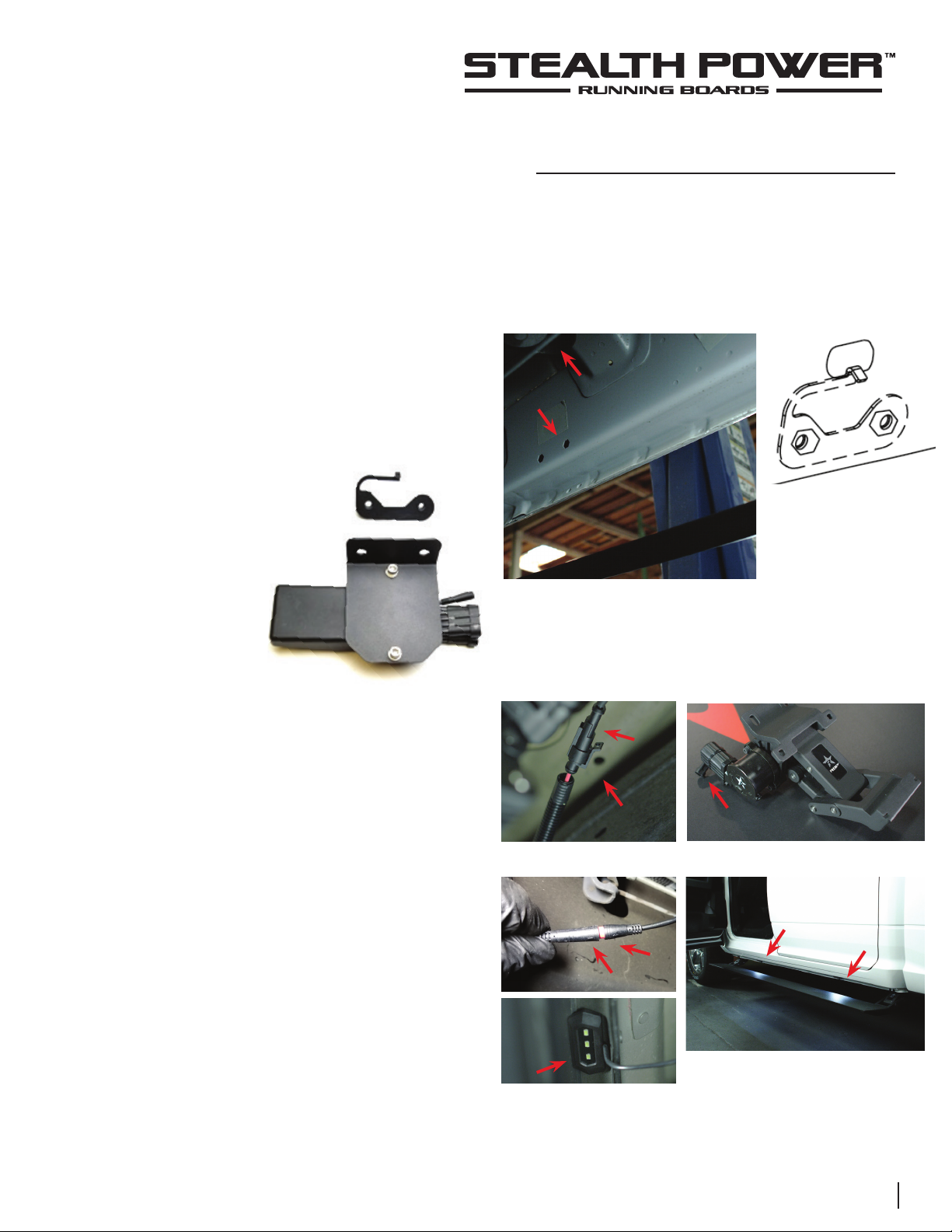
Step 10: Install the controller bracket using two M8 flange bolts.
Using a torque wrench, tighten to 18 ft-lb.
Step 11: Locate the electrical pigtail with the female socket
connector on the driver side front and rear motors. Route the
electrical harness from the controller along the frame rail
of the truck. Connect the male plug connector on the wire
harness into the female socket on the motor. The harness is
labeled Front Left for the front Driver motor and Rear Left for
the rear driver side motor.
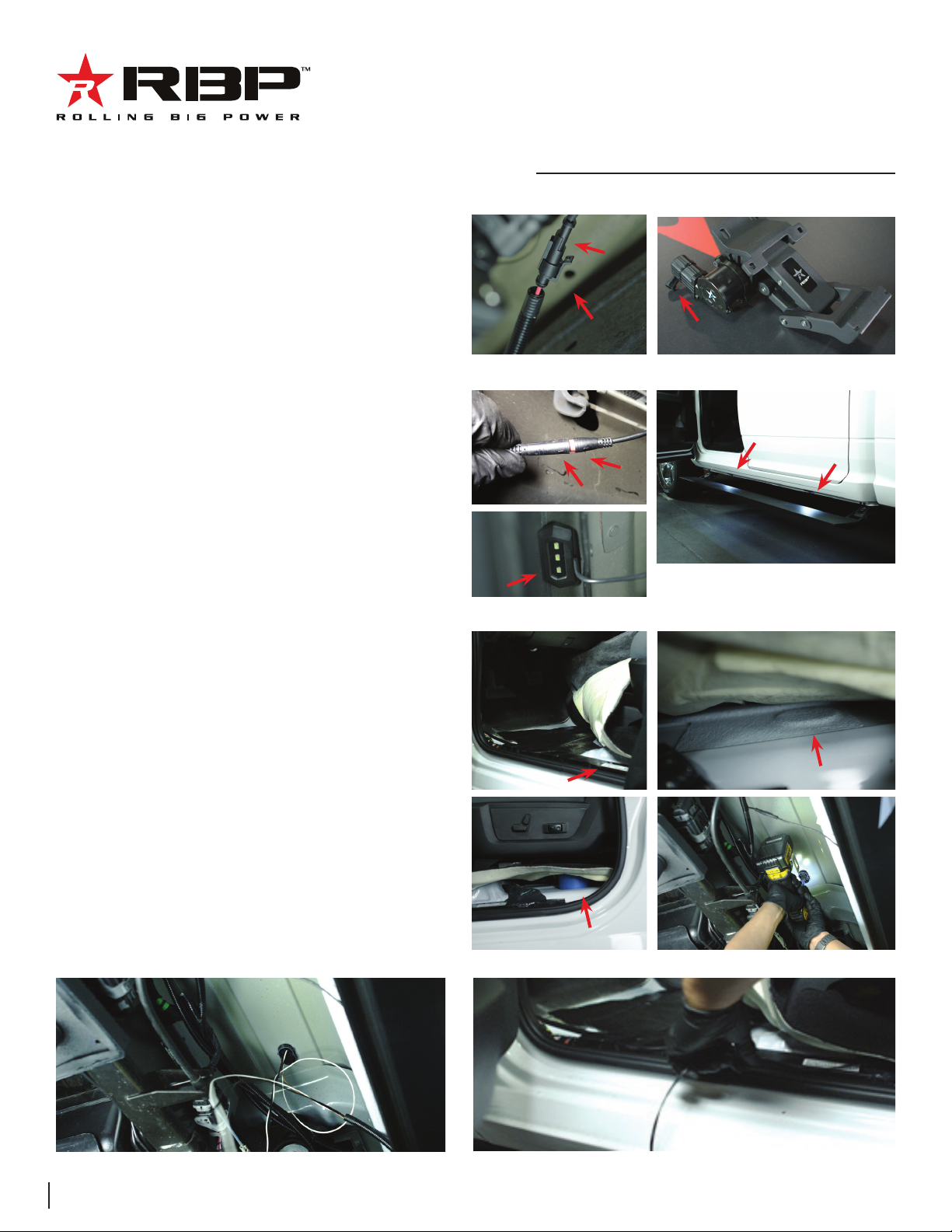
Step 12: Align the arrows on the small round connectors and
plug the driver side front and driver side rear LED lights. Prepare
the surface by cleaning with a 50/50 mix of isopropyl alcohol and
water or equivalent. Once the surface is completely dry, peel the
backing from the double-sided tape and stick the LEDs to the
bottom side of the rocker panel. Stick the LED lights at the center
of the front and rear driver side doors.
Step 13: Route the motor and LED wire harness from the
controller on the driver side of the vehicle to the passenger
side frame rail of the vehicle. When routing the harness keep
clear from any moving parts and avoid direct contact with the
exhaust system.
INSTALLATION INSTRUCTIONS
Step 9
Install controller
bracket here
Center body mount
threaded insert
Controller mounting bracket
Step 11
Step 12
10 WWW.ROLLINGBIGPOWER.COM
INSTALLATION INSTRUCTIONS
Step 14: Install the controller bracket using two M8
flange bolts and on M8 Hex Nut for the bottom bolt.
Using a torque wrench, tighten to 18 ft-lb.
Step 15: Align the arrows on the small round
connectors and plug the passenger side front and
passenger side rear LED lights. Prepare the surface
by cleaning with a 50/50 mix of isopropyl alcohol and
water or equivalent. Once the surface is completely
dry, peel the backing from the double-sided tape and
stick the LEDs to the bottom side of the rocker panel.
Stick the LED lights at the center of the front and rear
passenger side doors.
Step 16: On the driver side, remove the front kick
panel, front door sill trim panel, b-pillar trim panel
and pull the front driver carpet back. Now go under
the truck and locate the plastic grommet on the driver
side floorboard. Drill a 7/16” hole as shown.Make
sure not to drill through the carpet. We recommend
placing something between the floorboard and the
carpet to keep it away from the drill bit when it
breaks through.
Step 17: Feed the door trigger signal wires (white
and brown) and the disable switch wires (two black
wires) into the cab. Seal around the wires using RTV
silicone adhesive to prevent water intrusion.
Step 14
Step 15
Step 16
Step 17 Step 18