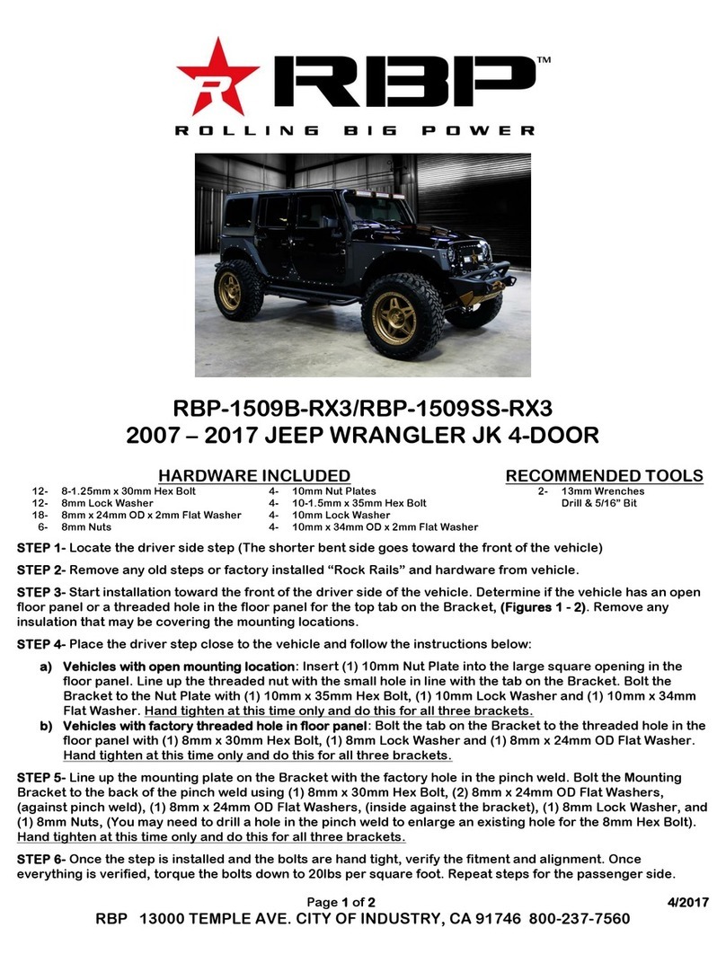
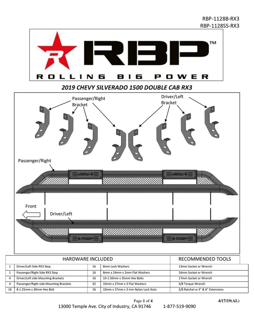
RBP STEALTH POWER RBP-216-SP User manual

INSTALLATION COVERS
PART# RBP-216-SP
FOR APPLICATIONS:
2009-2018 RAM 1500 CREW CAB
INSTALLATION GUIDE

2WWW.ROLLINGBIGPOWER.COM
Your Complete Satisfaction is Our Number One Goal at Rolling Big Power, your
satisfaction is why we’re in business. If for any reason your experience with our
product was anything less than satisfactory, please reach out to us. We’d love to
have the opportunity to provide the product experience and service you deserve.
APPLICATIONS:
2009-2018 RAM 1500 CREW CAB
TOOLS REQUIRED
•5 MM ALLEN WRENCH
•13 MM SOCKET AND WRENCH
•10 MM COMBINATION WRENCH
•ELECTRIC DRILL
•10 MM NUT DRIVER TIP
•RAZOR BLADE
•RTV SILICONE
•50/50 MIX OF ISOPROPYL ALCOHOL
AND WATER
•1” WIDE MASKING TAPE
•MEASURING TAPE
• TORQUE WRENCH
For Installation Instruction videos visit our YouTube page at:
https://www.youtube.com/user/rollingbigpowertv
STOP. DO NOT RETURN TO THE STORE. WE CAN HELP. QUESTIONS OR PROBLEMS, OUR
TEAM OF PROFESSIONALS ARE HERE TO HELP.
CALL TOLL FREE 1-877-519-9090, MON-FRI: 8:00AM - 5:00PM PST

3
1-877-519-9090
CONTENTS
ENGLISH
Product Technical Specifications 04
Product Packing List 05
Installation 07
Warranty Information 14

4WWW.ROLLINGBIGPOWER.COM
PRODUCT TECHNICAL SPECIFICATIONS
Rated Voltage: 12V
Load Rating: 600 lbs per side
Gross Weight: 55 lbs
Horizontal Extension: 6.4”
(Horizontal distance between the edge of power board and the vehicle door when the
board extends)
Step Height: 12.4”
(Vertical height difference between the edge of power board and the vehicle door while
board extending.)
WARNING: Keep a minimum of 10” safe distance while the Stealth Power™Running
Board is operating to avoid any personal injury or damage to the running boards.
Stealth Power™Running Boards are not designed to provide vehicle body protection.
Components can be damaged by hard impact or contact with foreign objects.
6.4”
12.4”

5
1-877-519-9090
Stealth Power™Running Board Parts List
Please verify that all listed components were included in your package. If
not, please call our team at 877-519-9090 for assistance.
Left Front Motor Linkage 20×1
Left Rear Motor Linkage 20×1
Right Front Motor Linkage 20×1
Right Rear Motor Linkage 20×1
Hexagon Flange Bolt ×8
20A Fuse×2
LED Lamp Module×4
Wired Magnetic Induction
Module ×2
Magnet ×4
Hexagon Flange Bolt ×1
Hexagon Flange Bolt ×8Connecting Bracket 10×5
(Two of them are in reserve.)
Socket Cap Screw ×8
Controller mounting bracket

6WWW.ROLLINGBIGPOWER.COM
PRODUCT PACKING LIST
Notice: As shown in the picture, there is a four-
conductor plug, a six-conductor plug, a black two-
conductor plug, and a red two-conductor plug.
Controller Assembly
Motor
Motor
Motor
Motor
LED lights LED lights
LED lights
LED lights
High Temperature
Protective Sleeve
Black, Disable switch
Brown, door trigger
White, door trigger
Black 12V -,
Red 12V+
Disable switch

7
1-877-519-9090
Step 1: Disconnect the battery. Begin with the negative battery terminal,
followed by the positive terminal.
Step 2:Inspect the front Driver side and rear Driver side motor mounting
points on the truck. If your truck is equipped with threaded inserts as
shown, skip to Step 5.
Step 3: Holes that do not have factory threaded inserts will require the
threaded nut bracket that is included in this kit. To install it, feed the
bracket through the slot and let it hang from the small tab as shown.
Hang Tab
Installation Position
FRONT
INSTALLATION INSTRUCTIONS
Step 1
Step 4
Step 3
Rear Driver
Side Motor
Mounting point
Front Driver
Side Motor
Mounting point
Step 4: Install the rear Driver side motor using two M6 flange bolts to
fasten the motor to the pinch seam and two M8 flange bolts to fasten
the motor to the threaded nut bracket. Hold the bracket by the hang tab
to avoid it falling into the rocker panel. The hardware should be hand
tightened only until snug. This will allow the motor assembly to move
and align easier when installing the running board.

8WWW.ROLLINGBIGPOWER.COM
Step 5: Install the front Driver side motor using two M6 flange bolts to fasten the motor to the pinch seam and two M8
flange bolts to fasten the motor to the threaded nut bracket. Hold the bracket by the hang tab to avoid it falling into the
rocker panel. The hardware should be hand tightened only until snug. This will allow the motor assembly to move and
align easier when installing the running board.
Step 6: Install the Driver Side running board.
6a. Begin by propping up the running board on the front and rear motor assembly bases.
6b. Next align the sliding T-Nut assemblies on the running board with the slots on the front and rear motor bases.
6c. Once the T-nuts are aligned, rotate the running board so that the T-nuts drop into the slots on the base of the arms.
6d. Secure the running board to the arms using the M6 x 25 socket head cap screws. Using a torque wrench, tighten to 9 ft-lbs.
INSTALLATION INSTRUCTIONS
Step 5A Step 5B
Step 6A
Step 6C
Step 6B
Step 6D

9
1-877-519-9090
Step 7: Now that the running board is installed, go back and tighten the hardware on the Driver Side front and rear motor
assemblies. Using a torque wrench, tighten the mounting hardware to 18 ft-lbs.
Step 8: Repeat steps 2-7 to install the motor linkage assemblies and running board on the Passenger Side.
Step 9: Locate factory step mounting hole pattern just below the
middle body mount on the driver side of the truck. Peel the tape
covering the large slot. Feed the threaded bracket through the slot
and let it hang from the small tab as shown.
Step 10: Install the controller bracket using two M8 flange bolts.
Using a torque wrench, tighten to 18 ft-lb.
Step 11: Locate the electrical pigtail with the female socket
connector on the driver side front and rear motors. Route the
electrical harness from the controller along the frame rail
of the truck. Connect the male plug connector on the wire
harness into the female socket on the motor. The harness is
labeled Front Left for the front Driver motor and Rear Left for
the rear driver side motor.
Step 12: Align the arrows on the small round connectors and
plug the driver side front and driver side rear LED lights. Prepare
the surface by cleaning with a 50/50 mix of isopropyl alcohol and
water or equivalent. Once the surface is completely dry, peel the
backing from the double-sided tape and stick the LEDs to the
bottom side of the rocker panel. Stick the LED lights at the center
of the front and rear driver side doors.
Step 13: Route the motor and LED wire harness from the
controller on the driver side of the vehicle to the passenger
side frame rail of the vehicle. When routing the harness keep
clear from any moving parts and avoid direct contact with the
exhaust system.
INSTALLATION INSTRUCTIONS
Step 9
Install controller
bracket here
Center body mount
threaded insert
Controller mounting bracket
Step 11
Step 12

10 WWW.ROLLINGBIGPOWER.COM
INSTALLATION INSTRUCTIONS
Step 14: Install the controller bracket using two M8
flange bolts and on M8 Hex Nut for the bottom bolt.
Using a torque wrench, tighten to 18 ft-lb.
Step 15: Align the arrows on the small round
connectors and plug the passenger side front and
passenger side rear LED lights. Prepare the surface
by cleaning with a 50/50 mix of isopropyl alcohol and
water or equivalent. Once the surface is completely
dry, peel the backing from the double-sided tape and
stick the LEDs to the bottom side of the rocker panel.
Stick the LED lights at the center of the front and rear
passenger side doors.
Step 16: On the driver side, remove the front kick
panel, front door sill trim panel, b-pillar trim panel
and pull the front driver carpet back. Now go under
the truck and locate the plastic grommet on the driver
side floorboard. Drill a 7/16” hole as shown.Make
sure not to drill through the carpet. We recommend
placing something between the floorboard and the
carpet to keep it away from the drill bit when it
breaks through.
Step 17: Feed the door trigger signal wires (white
and brown) and the disable switch wires (two black
wires) into the cab. Seal around the wires using RTV
silicone adhesive to prevent water intrusion.
Step 14
Step 15
Step 16
Step 17 Step 18

11
1-877-519-9090
INSTALLATION INSTRUCTIONS
Step 18: Route the driver side door trigger wire (brown) towards
the driver side b-pillar. Route the passenger side door trigger
wire (white) under the center console and over to the passenger
side b-pillar. Route the black disable switch wires to the center
console.
Step 19: The door trigger sensor harness will need a ground
connection to the vehicle. Locate the seat belt assembly at the
driver side b-pillar and install the ground wire under the top bolt
of the seat belt assembly.
Step 20: Connect the snap in bullet connector to the brown wire
on the passenger side.
Step 21: Apply a vertically oriented strip of masking tape on
the front driver side door using the deepest part of the latch as
a reference point. Make a mark 1.5” below the center line of
the latch. Prepare the surface by cleaning with a 50/50 mix of
isopropyl alcohol and water or equivalent. Once the surface is
completely dry, peel the backing from the double-sided tape and
stick the magnet to the door. Align the top of the magnet with the
1.5” mark as shown.
Step 22: Apply a vertically oriented strip of masking tape on
the door jamb using the outer edge of the front driver side door
striker as a reference point. Make a mark 1.5” below the center
line of the striker. Lift the bulb door seal to route the sensor wire
underneath it. Prepare the surface by cleaning with a 50/50 mix
of isopropyl alcohol and water or equivalent. Once the surface is
completely dry, peel the backing from the double-sided tape and
stick the sensor to the door jamb. Align the top of the sensor with
the 1.5” mark as shown.
Step 19
Step 20
Step 21 Front door magnet
Latch
Striker
Tape application
reference point
Tape application
reference point
Bulb door seal
Front door sensor
0”
0”
1.5”
1.5”
Step 22

12 WWW.ROLLINGBIGPOWER.COM
INSTALLATION INSTRUCTIONS
Step 23
Step 24
Step 25
Flush with tape
Flush with bulb seal
Step 23: Apply a horizontally oriented strip of masking tape on the
rear driver side door jamb using the door detent as a reference
point. Make a mark 0.5” from the edge marked as 0”. Prepare
the surface by cleaning with a 50/50 mix of isopropyl alcohol and
water or equivalent. Lift the bulb door seal to route the sensor wire
underneath it. Once the surface is completely dry, peel the backing
from the double-sided tape and stick the rear door sensor to the
door jamb. Align the top left corner of the sensor with the 0.5”
mark as shown.
Step 24: Extend the masking tape used for the sensor over to the
inside door trim panel as shown. Prepare the surface by cleaning
with a 50/50 mix of isopropyl alcohol and water or equivalent.
Once the surface is completely dry, peel the backing from the
double-sided tape and stick the magnet to the door. Align the top
edge of the magnet with the tape and the right side of the magnet
with bulb seal as shown.
Step 25: Repeat steps 19-24 to install the passenger side door
trigger sensors and magnets. The passenger side door trigger
harness is connected to the white wire that was routed under the
carpet to the driver side b-pillar in step 18.
Step 26: Remove the left center console trim panel. Prepare the
surface by cleaning with a 50/50 mix of isopropyl alcohol and
water or equivalent. Once the surface is completely dry, peel the
backing from the double-sided tape and stick the disable switch on
the lower dash panel. Plug the disable switch connector into the
black wire harness that was routed under the carpet to the center
console in step 18.
From the controller
Disable switch
Rear door
sensor
Rear door
magnet
Door detent 0” 1.5”
Horizontal strip of tape
Disable switch
Left center
console trim
panel

“I” Running boards are On
“O” Running boards are Off
Thank you for choosing RBP! We hope you enjoy your new
Stealth Power Running Boards. We would love to hear about
your experience and see your vehicle decked out with our
products. To share simply tag us using #Rollingbigpower,
#RBP or #RBPStealthPower or DM us on Facebook and
Instagram and visit us on YouTube!
FOLLOW US
OfficialRBP
@rollingbigpower
RollingBigPowerTV
13
1-877-519-9090
INSTALLATION INSTRUCTIONS
Step 27: Install the left center console trim panel and tuck
the disable switch harness behind the lower dash panel
Step 28: Remove the 20 Amp fuses from the main
positive and negative 12V power leads on the main
harness. Route the power wires over the wheel well and
into the engine compartment. Connect the ring terminals
to the battery positive and negative posts.
Step 29: Install the 20 Amp fuses back on the main
negative and positive 12V power leads of the main power
harness.
Step 30: Connect the battery. Begin with the positive
terminal, followed by the negative terminal.
Step 31: Open and close all four doors to test the operation
of your new Stealth Power Running boards. Please note that
there is a 4 second delay for the running boards to retract
after the doors are closed.
Step 32: Open the driver side door and keep the door open.
Flip the disable switch to the “O” or Off position. This will
signal the running boards to retract to the stowed position
and it will disable any further operation until the switch is
flipped to the “I” or On position.
Step 27
Step 30
Step 28
Disable switch
Lower dash panel

14 WWW.ROLLINGBIGPOWER.COM
Rolling Big Power believes in true customer satisfaction. We strive to provide you, our
customer, with a delightful experience with our products. In the event that your experience
is not delightful - please contact us and allow one of our professional customer service
agents take care of you. Our primary goal is for you to become a customer for life - we’re
willing to earn it.
Rolling Big Power warrants that any RBP product purchased from an RBP Authorized
Resellers will be free from any defects in manufacturing, materials and workmanship for
five years from original date of purchase, for the original purchaser for the product installed
on the purchaser’s original vehicle. Please validate your warranty by REGISTERING YOUR
RBP PRODUCT.
NOTE: If you purchased an RBP product from an unauthorized reseller, the unauthorized
reseller your warranty may or may not be honored. It is strongly recommended that you
purchase RBP products from an RBP Authorized Resellers. To view dealers currently
authorized to sell Rolling Big Power products, visit our website to see a complete list.
During the 5-year warranty period, RBP provides free replacement for any manufacturer’s
defects. RBP reserves the right to replace any individual component of the system, or the
entire system at its sole discretion. RBP provides a limited lifetime warranty against rust on
the running board assemblies for the original purchaser. Proof of purchase is required when
submitting a request for warranty replacement. Within the limit of law, the interpretation of
warranty policy solely belongs to RBP.
RBP STEALTH POWER WARRANTY

15
1-877-519-9090
RBP STEALTH POWER WARRANTY
Exclusions to the RBP Stealth Power Warranty:
· Any product improperly installed, altered, lack of or improper maintenance or improper
use of our products.
·No proof of purchase or RBP warranty registration as noted above
·Purchased from an unauthorized reseller
·Failure due to misuse, abuse, neglect or impact/collision
·Any cosmetic scratches or discoloration or any other cosmetic condition that does
not affect mechanical operations
·Failure caused by force majeure
·Improper maintenance or care
·Any and all costs of removal, installation, freight, incidental or consequential damages
are excluded from this warranty.

16 WWW.ROLLINGBIGPOWER.COM
WWW.ROLLINGBIGPOWER.COM
1-877-519-9090
®
FOLLOW US
Other RBP Automobile Accessories manuals

RBP
RBP RBP-FSRB1118 User manual

RBP
RBP RBP-1509B-RX3 User manual

RBP
RBP RBP-1306B-RX3 User manual

RBP
RBP RBP-1308B-RX3 User manual

RBP
RBP RBP-1510B-RX3 User manual

RBP
RBP RBP-1414B-RX3 User manual

RBP
RBP RBP-325B-RX7 User manual

RBP
RBP RBP-1109B-RX3 User manual

RBP
RBP STEALTH POWER RBP-217-SP User manual

RBP
RBP Stealth Power RBP-510-SP User manual