2
Drawing No. LP1143 Effective 08 2021
HARDWARE INSTALLATION
Installing a Module
To a 4.3 inch Host
1. To install a module on the tall side of a 4.3 inch host, align the
latches of the module with the host case such that the
backplane connector shroud on the module cover aligns with
the backplane connector opening in the host case.
2. To install a module on the short side of a 4.3 inch host, rotate
the module 180 degrees and align the latches on the host
with the module case so that the I/O connector is facing
downward.
3. Insert the host latches into the openings in the module case
by slightly deflecting the latches inward.
4. Press the module into the host case evenly until the latches
engage.
5. Install Module Locks between each module as shown by fully
inserting the legs of the Module Locks into the slots in the
case until the button on the Module Lock aligns with the hole
provided in the case. Press fit the button into the hole. Repeat
this installation between each module in your system to
provide the most secure installation.
6. When you have finished adding modules, the rear cover
should be installed in the same manner as the modules.
To a 3.5 inch Host
1. Align the latches of the module with the host case such that
the backplane connector shroud on the module cover aligns
with the backplane connector opening in the host case.
WARNING - Disconnect all power to the unit before
installing or removing modules.
AVERTISSEMENT - Débranchez l’alimentation électrique
de l’appareil avant d’installer ou de retirer des modules.
Installation of the product must comply with National Electrical
Code (NEC), NFPA-70 or Canadian Electrical Code (CED) or any
local regulation Authority.
Short Side
Tall Side
Position 1
Rear Cover
It is recommended that a
relay module be installed
in Module Position 1 only
(shown below).
Rear Cover
Position 1
It is recommended that a
relay module be installed
directly onto the back of
the host (shown below),
not on the back of any
other module.
SPECIFICATIONS
Note: The PM-50 4.3 inch host accepts a maximum of 5
modules while the 3.5 inch host accepts a maximum of 3.
Only one module from each function type (i.e. communication,
relay, analog output) can be installed.
1. POWER: Power is supplied by the PM-50 host device.
Must use a Class 2 circuit according to National Electrical
Code (NEC), NFPA-70 or Canadian Electrical Code (CEC),
Part I, C22.1 or a Limited Power Supply (LPS) according to
IEC/EN 60950-1 or Limited-energy circuit according to IEC/
EN 61010-1.
Max Power: 0.55 W
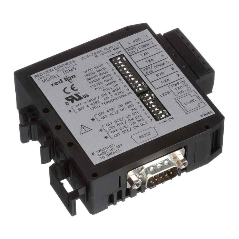
2. RS232 COMMUNICATIONS: Field installable module
Isolation: 1000 Vrms for 1 minute
Baud Rate: 300 to 115200
Data Format: 7/8 bits; odd, even or no parity
3. ENVIRONMENTAL CONDITIONS:
Operating Temperature Range: -10 to 55 °C
Storage Temperature Range: -40 to 85 °C
Vibration to IEC 68-2-6: Operational 5-500 Hz, 2 g
Shock to IEC 68-2-27: Operational 20 g
Operating and Storage Humidity: 0 to 85% max. RH non-
condensing
Altitude: Up to 2000 meters
Installation Category II, Pollution Degree 2 as defined in IEC/
EN 60664-1.
4. CERTIFICATIONS AND COMPLIANCES:
CE Approved
EN 61326-1 Immunity to Industrial Locations
Emission CISPR 11 Class A
IEC/EN 61010-1
RoHS Compliant
UL Hazardous: File # E317425
Rugged IP20 enclosure
5. CONSTRUCTION: Plastic enclosure with IP20 rating. For use
only in an approved enclosure.
6. CONNECTIONS: High compression cage-clamp terminal
blocks
Wire Strip Length: 0.32-0.35" (8-9 mm)
Wire Gauge Capacity: Four 28 AWG (0.32 mm) solid,
two 20 AWG (0.61 mm) or one 16 AWG (2.55 mm)
Torque: 2 inch-lbs (0.23 N-m)
7. WEIGHT: 1.4 oz (39.7 g)
