manuals.online logo
Brands
  1. Home
  2. •
  3. Brands
  4. •
  5. ReelCraft
  6. •
  7. Tools
  8. •
  9. ReelCraft L 4000 118 User manual

ReelCraft L 4000 118 User manual

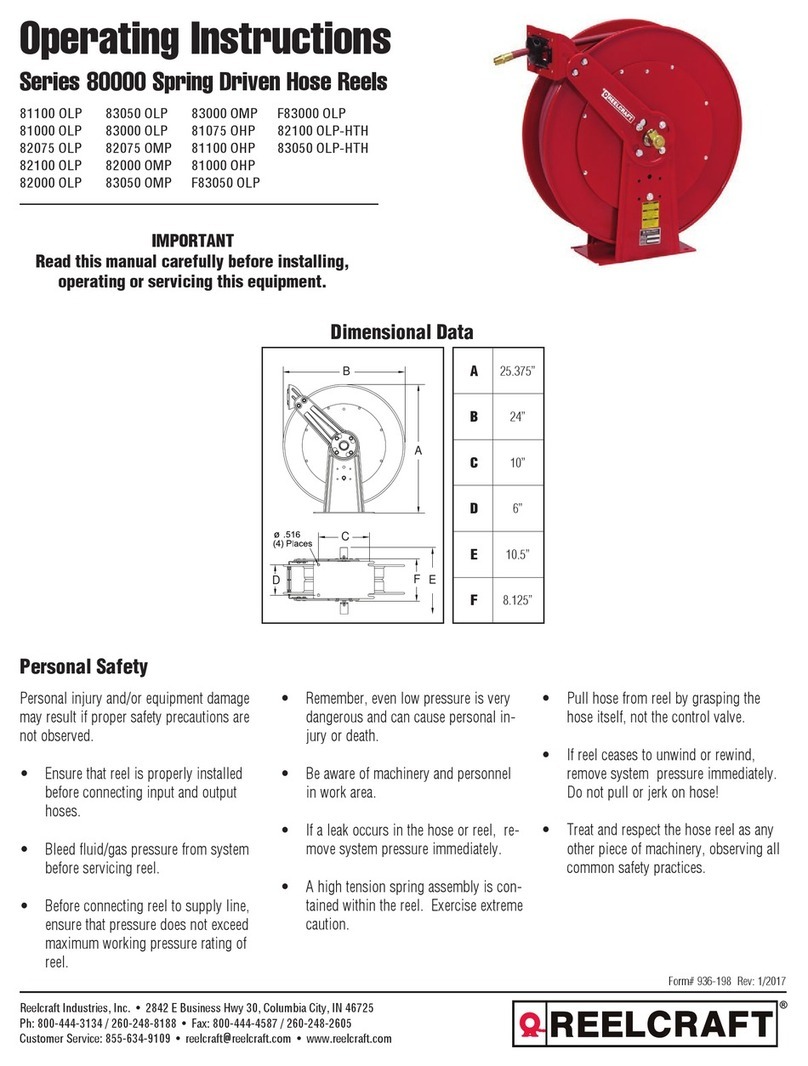
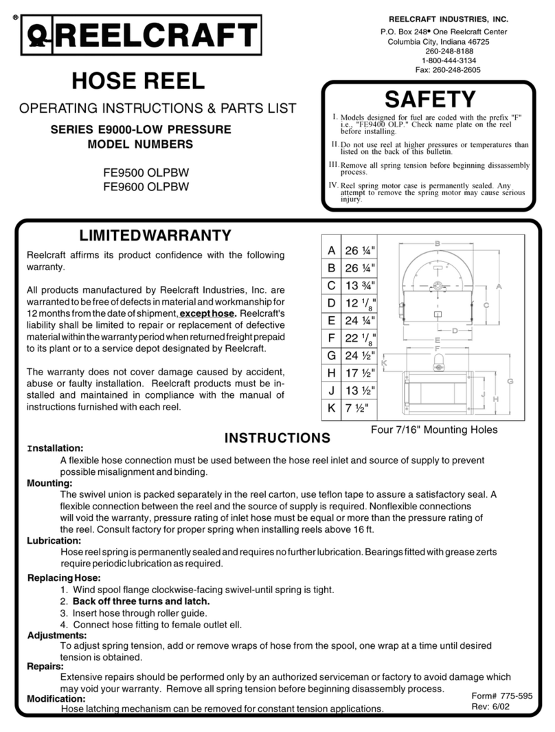
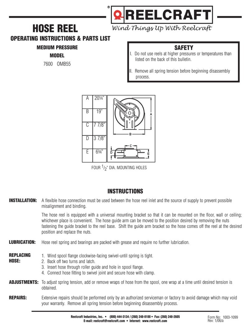
Operating Instructions
CE Spring Driven Cord Reels
Reelcraft International Inc. • Ph: +44 (0) 1536 406999 • Fax: +44 (0) 1536 406777
Unit 17 - Cronin Courtyard, Weldon South Industrial Estate, Corby - Northamptonshire NN18 8AG
[email protected] • www.reelcraft.com/europe
Form# 1290-1116 Rev: 10/2018
WARNING: Even low voltage can cause
irreparable damage or death! Exercise
extreme caution while operating or
servicing this equipment.
IMPORTANT
Read this manual carefully
before installing,
operating or servicing this
equipment.
Personal injury and/or equipment damage may
result if proper safety precautions are not
observed.
• Ensure that only a qualified electrician
installs/services this equipment.
• Ensure that power supply voltage does not
exceed maximum voltage rating of reel.
• Ensure that reel is properly installed before
connecting to power supply.
• Ensure that all electrical power is removed
from reel before servicing.
• A high-tension spring is contained within the
reel. Exercise extreme caution.
• Check for frayed and/or broken wires before
each use. Pull cord from reel by grasping the
cord itself, not the work device.
• If an electrical malfunction should occur,
remove power from reel immediately.
• Ensure that reel, cord, and equipment being
serviced are properly grounded. Use an
ohmmeter to check ground continuity.
• If reel ceases to unwind or rewind, remove
power immediately. Do not pull or jerk on
electrical cord!
• Treat and respect the reel as any other piece
of machinery, observing all common safety
practices.
Safety Precautions
L 4000 118 L 4545 123 X 118 L 5550 124 X 118 L 70100 123 X 118
L 4100 118 L 5000 118 L 5700 118 L 70100 124 118
L 4500 118 L 5500 118 L 70100 118 L 70100 124 X 118
L 4000
L 4100
L 4500
L 5000 L 5500 L 5700
A327 mm 365 mm 448 mm 448 mm
B321 mm 362 mm 425 mm 425 mm
C203 mm 248 mm 248 mm 248 mm
D64 mm 64 mm 64 mm 64 mm
E238 mm 267 mm 267 mm 318 mm
F44 mm 54 mm 54 mm 54 mm
L 70000
with
pigtail
L 70000
bare
reels
A514 mm 514 mm
B502 mm 502 mm
C198 mm 198 mm
D98 mm 98 mm
E298 mm 318 mm
Part No. Cable Nominal
AC Voltage
Nominal Output with Cable Weight
Fully Wound Unwound
L 4000 118 15m H07RN-F 3G1.5* 220 V 1430 W 1430 W 10 kg
L 4100 118 12m H07RN-F 4G1.5* 220 V 1100 W 1100 W 10 kg
L 4500 118 13.5m H07RN-F 3G2.5* 220 V 3520 W 3520 W 10 kg
L 5000 118 10.5m H07RN-F 3G6* 220 V 3300 W 3300 W 13 kg
L 5500 118 15m H07RN-F 3G2.5* 220 V 3520 W 3520 W 16 kg
L 5700 118 15m H07RN-F 3G6* 220 V 3300 W 3300 W 17 kg
L 70100 118 30m H07RN-F 3G2.5* 220 V 3520 W 3520 W 26 kg
L 70100 124 118 30m H07RN-F 4G4* 220 V 3520 W 3520 W 26 kg
L 4545 123 X 118 13.5m H03RN-F 3G2.5 220 V 3520 W 3520 W 13 kg
L 5550 124 X 118 15m H07N-F 4G4 220 V 3520 W 3520 W 24 kg
L 70100 123 X 118 30m H07RN-F 3G2.5 220 V 3520 W 3520 W 39 kg
L 70100 124 X 118 30m H07RN-F 4G4 220 V 3520 W 3520 W 44 kg
*NOTE: Models provided without cable
CE Spring Driven Cord Reels
Page 2 www.reelcraft.com
Installation Instructions
Mounting
CAUTION: Unless reel was specified differ-
ently when ordering, maximum installation
height is 16 feet. Do not exceed this distance.
Ensure that only a qualified electrician installs/
services this equipment. Installation of GFCI
cord reels should be performed by a qualified
and licensed professional in accordance with
building codes and applicable NEC standards.
1. Unpack and inspect reel for damage. Turn
by hand to check for smooth operation.
Check for completeness.
2. Configure reel for top, side or bottom-
wind (bottom-wind for constant tension
reels only) electrical cord dispensing by
removing bolts (1), securing guide arm
bracket (2). Determine new guide arm
location and remove corresponding bolts.
Position guide arm bracket to reel and
replace bolts.
3. Position reel on floor, wall, or ceiling.
Secure into place, using four (customer
supplied) screws or bolts (3).
Installing the Input Electrical Cable
WARNING: Use only 2.5mm or better cable
for input wiring. Ensure that application does
not exceed electrical rating of reel (refer to
page 1 of this manual). All cord reels with
GFCI receptacles must be hard wired into the
electrical circuit. Use of 2 or 3 prong plugs
may cause a potential malfunction of the GFCI
receptacle.
1. Feed input cable (1) through elbow (2)
and main shaft. Make sure that input
cable extends 150 mm from collector.
2. Screw elbow (2) into reel.
3. Connect input wires (3) and collector
ring wires (4) together using wire nuts
(5). Reference label in slip ring cover for
connections.
4. Take the provided zip tie (not pictured)
and zip tie the input cable wires together
closest to the slip ring.
5. Assemble cover (6) to reel.
Installing the Output
Electrical Cable
WARNING: Select output cable in accordance
with power requirement of apparatus to be
supplied. Ensure that application does not
exceed electrical rating of reel (refer to page
1 of this manual). Use extreme caution, reel
under tension. Avoid releasing latch mecha-
nism.
1. Manually turn sheave (1) until spring is
tight, back off 2 turns, and latch.
2. Remove access cover (2).
3. Remove 150 mm of output cable jacket(3)
and add fork terminals(4) to ends.
4. Route cable through strain relief (6), then
through cut out in spool (7).
5. Pull enough cable through for roughly
1/2 an inner wrap as shown in the dia-
gram.
6. Connect output wires to terminal block
(8) as shown. Reference label in slip ring
cover for connections.
7. Connect ground wire to grounding stud
(9) as shown.
8. Using Ohmmeter check for ground faults.
9. Take provided cable clamp (not pictured)
and attach it to the wire. Then take the
cable clamp and screw it down to the
brush assembly on the reel.
10. Replace cover (2).
11. Release latch and wind cable onto reel.
12. Install bumper stop (10).
Adjustments - Spring Tension
If necessary, adjust spring tension on reel by
adding or removing wraps of electrical cord
from spool, one wrap at a time, until desired
tension is obtained. Add wraps to increase
tension. Remove wraps to decrease tension.
WARNING: When adding wraps of electrical
cord, be careful not to exceed the winding
mechanism’s spring capacity. Add just enough
wraps of cord to achieve the desired tension.
Damage to the winding mechanism will result
if spring is over-tensioned. Always be aware
of spring tension on reel. Exercise extreme
caution.
Installing Plugs
Install only CE conforming plug and coupling
rated to a minimum of 16 amps per manufac-
turer’s instructions before applying mains volt-
age. Do not install a male plug at each end.
Troubleshooting Instructions
Troubleshooting of the reel consists of isolat-
ing a problem to a defective electrical cord/
work device, brush holder/brushes, or col-
lector assembly. Refer any other discrepan-
cies only to an authorized service person or
directly to Reelcraft.
WARNING: The following procedure directs
the technician to take voltage measurements.
Remember, even low voltage is dangerous and
can cause personal injury or death. Exercise
extreme caution! Ensure that only a qualified
electrician installs/services this equipment.
1. If work device is either an incandescent
or fluorescent light, replace bulb with a
known good bulb. If this does not correct
the problem, proceed to step 2. If work
device is an electrical receptacle, ensure
that tool or fixture connected to it is in
good working order. If it is, proceed to
step 2.
1
2
3
4
5
6
2
1
5
3
9
4
8
7
6
10
1
2
1
2
3
CE Spring Driven Cord Reels
www.reelcraft.com Page 3
2. Remove power from reel.
3. Remove access cover (1).
4. Reapply power to reel.
5. Check for correct voltage (220 V AC)
at terminal strip (2). If voltage read-
ing is correct, replace output electri-
cal cord/work device (refer to Service
Instructions). If voltage reading is incor-
rect, proceed to step 6.
6. Remove power from reel.
7. Using ohmmeter, check continuity of
input electrical cord. If cord checks
good, proceed to step 8. If cord is faulty,
replace it (refer to Service Instructions).
8. Remove brush holder/brushes from reel
and inspect (refer to Service Instructions).
Replace defective components then pro-
ceed to step 9.
9. Reapply power to reel.
10. Check for correct voltage (220 V AC) at
terminal strip (2). If voltage reading is
still incorrect, replace defective collector
assembly (refer to Service Instructions).
11. Replace access cover (1).
Service Instructions
Maintain reel by following the service instruc-
tions given below. Refer all other repairs, other
than those listed, only to an authorized service
person or directly to Reelcraft. Failure to do so
can result in personal injury and/or equipment
damage and may void the warranty (refer to
page 5 when referencing parts).
WARNING: Remove power from reel
before performing any of the following
procedures.
Replacing the Output Electrical
Cord/Work Device
WARNING: Use extreme caution, reel under
tension. Avoid releasing latch mechanism.
1. Pull output electrical cord from reel until
fully extended, then latch.
2. Remove output electrical bumper stop
(7).
3. Disconnect output electrical cord/work
device (12) at terminal strip (10).
4. Remove strain relief (8). Remove output
electrical cord/work device.
5. Install replacement electrical cord/work
device by reversing steps 2 through 4.
6. Release latch and rewind electrical cord
on reel.
7. Replace access cover (1).
Replacing the Input Electrical Cord
WARNING: Use of 2 or 3 prong plugs on
cord reels equiped with GFCI receptacles may
cause a potential malfunction of the GFCI
receptacle.
1. Remove wire nuts (15) securing input
electrical cord to collector assembly (13).
2. Remove 90 degree elbow (9).
3. Remove input electrical cord.
4. Remove 280 mm of outer jacket from
replacement input electrical cord (input
electrical cord wires must protrude a
minimum of 150 mm from center of col-
lector assembly).
5. Install replacement input electrical cord
by reversing steps 1 through 3.
6. Replace access cover (1).
Replacing the Brush
Holder/Brushes
1. At terminal strip (10), remove wires con-
necting brushes (11) to terminal strip.
2. Remove lock nuts (3) securing brush
holder (6) to reel. Relocate cable clamp
temporarily and remove brush holder.
3. Remove brushes (4) from brush holder
(6).
4. Install replacement brush holder/brushes
by reversing steps 1 through 3. Upon
completion of installation, adjust brush-
to-ring alignment by loosening nuts (5)
and sliding finger assembly (2).
Replacing the Collector Assembly
1. Remove wire nuts (15) securing input
electrical cord to collector assembly.
2. At terminal strip (10), disconnect wires
(11) connecting brushes (4) to terminal
strip.
3. Remove lock nuts (3) securing brush
holder (6) to reel. Relocate cable clamp
temporarily and remove brush holder.
4. Remove snap ring (14).
5. Remove collector assembly (13).
6. Install replacement collector assembly
by reversing steps 1 through 5. Upon
completion of installation, adjust brush-
to-ring alignment by loosening nuts (5)
and sliding finger assembly (2).
7. Replace access cover (1).
1
2
3
4
5
6
7
8
9
10
11
15 14 13 12
CE Spring Driven Cord Reels
www.reelcraft.com Page 4
Earthing concept
(1) Earthing cable
(2) Fastening screw
1. Connect the earthing cable,
which is part of the delivery,
by means of the fastening
screw to the frame of the
reel.
2. Use the unpainted position
intended for this purpose.
3.
Connect the other end of the
cable with the earth potential
.
4. Check the connection by
means of an ohmmeter with
regard to conductivity.
5.
Check this connection for rust
each time you use the hose
reel and ensure electrical
discharge capability at any
time.
Type identification plate (see samples below)
The first two digits of the serial number indicate the year of manufacture i.e. in the
above example the year of manufacture is 2013
Manufacturer
Service and EU
-
Representative
Reelcraft Inc.
2842 E. Business Hwy 30 Columbia City
IN 46725
USA
Reelcraft International Inc.
Unit 17, Cronin Courtyard
Weldon South Industrial Estate
Corby Northamptonshire
NN18 8AG United Kingdom
1
2
Part number: (included in the original delivery)
600000-ATX

This manual suits for next models

11

Other ReelCraft Tools manuals

ReelCraft D9000 Series User manual

ReelCraft

ReelCraft D9000 Series User manual

ReelCraft 7000 Series User manual

ReelCraft

ReelCraft 7000 Series User manual

ReelCraft 5005 Series User manual

ReelCraft

ReelCraft 5005 Series User manual

ReelCraft 5000 Series User manual

ReelCraft

ReelCraft 5000 Series User manual

ReelCraft 7600 User manual

ReelCraft

ReelCraft 7600 User manual

ReelCraft 30000 Series User manual

ReelCraft

ReelCraft 30000 Series User manual

ReelCraft TH5000 Series User manual

ReelCraft

ReelCraft TH5000 Series User manual

ReelCraft 7600 OLP User manual

ReelCraft

ReelCraft 7600 OLP User manual

ReelCraft D83000 OLP User manual

ReelCraft

ReelCraft D83000 OLP User manual

ReelCraft D8600 OLP Use and care manual

ReelCraft

ReelCraft D8600 OLP Use and care manual

ReelCraft 80000 Series User manual

ReelCraft

ReelCraft 80000 Series User manual

ReelCraft PW7000 Series User manual

ReelCraft

ReelCraft PW7000 Series User manual

ReelCraft 7000 Series User manual

ReelCraft

ReelCraft 7000 Series User manual

ReelCraft 7830 OLP User manual

ReelCraft

ReelCraft 7830 OLP User manual

ReelCraft 30000 Series Use and care manual

ReelCraft

ReelCraft 30000 Series Use and care manual

ReelCraft 7000 Series User manual

ReelCraft

ReelCraft 7000 Series User manual

ReelCraft REELSAFE RS7000 Series User manual

ReelCraft

ReelCraft REELSAFE RS7000 Series User manual

ReelCraft 5400 OLP Use and care manual

ReelCraft

ReelCraft 5400 OLP Use and care manual

ReelCraft LD2030 163 9 User manual

ReelCraft

ReelCraft LD2030 163 9 User manual

ReelCraft 5000 Series User manual

ReelCraft

ReelCraft 5000 Series User manual

ReelCraft 5000 Series User manual

ReelCraft

ReelCraft 5000 Series User manual

ReelCraft L 5000 Series User manual

ReelCraft

ReelCraft L 5000 Series User manual

ReelCraft D80000 Series User manual

ReelCraft

ReelCraft D80000 Series User manual

ReelCraft LP80000 Series User manual

ReelCraft

ReelCraft LP80000 Series User manual

Popular Tools manuals by other brands

Sealey SM353CE.V3 instructions

Sealey

Sealey SM353CE.V3 instructions

T&S B-1460-SMB Installation and maintenance instructions

T&S

T&S B-1460-SMB Installation and maintenance instructions

Trane TurboTorch user manual

Trane

Trane TurboTorch user manual

Hilti NPR 019 IE-A22 manual

Hilti

Hilti NPR 019 IE-A22 manual

Nederman 886 user manual

Nederman

Nederman 886 user manual

BEA AT-A22 manual

BEA

BEA AT-A22 manual

VERITAS Mk.II manual

VERITAS

VERITAS Mk.II manual

Beta 599DGT Instructions for use

Beta

Beta 599DGT Instructions for use

Hilti TE 2000-22 manual

Hilti

Hilti TE 2000-22 manual

BEA 145/13-779C Spare parts list/service instructions

BEA

BEA 145/13-779C Spare parts list/service instructions

Makita HR2430 instruction manual

Makita

Makita HR2430 instruction manual

Hubbell HBL45123C installation instructions

Hubbell

Hubbell HBL45123C installation instructions

Rehau Rautool M1 operating instructions

Rehau

Rehau Rautool M1 operating instructions

Ryobi P4003 Operator's manual

Ryobi

Ryobi P4003 Operator's manual

TKR Group 83 30 5 A87 F94 Translation of the original manual

TKR Group

TKR Group 83 30 5 A87 F94 Translation of the original manual

Sealey Professional TOOLS VS4464 instructions

Sealey

Sealey Professional TOOLS VS4464 instructions

Mighty Seven SN-1268 manual

Mighty Seven

Mighty Seven SN-1268 manual

Dolby Laboratories DP590 quick start guide

Dolby Laboratories

Dolby Laboratories DP590 quick start guide

manuals.online logo
manuals.online logoBrands
  • About & Mission
  • Contact us
  • Privacy Policy
  • Terms and Conditions

Copyright 2025 Manuals.Online. All Rights Reserved.