Reflex Servitec 35-120 User manual

Servitec 35-120 with Touch controller 06.07.2016 - Rev. B
Vacuum spray degassing
GB
Operating manual
Original operating manual


Contents
Servitec 35-120 with Touch controller — 06.07.2016 - Rev. B English —
3
English
Contents
1Notes on the operating manual.....................................................................................................................................................5
2Liability and guarantee...................................................................................................................................................................5
3Safety................................................................................................................................................................................................6
3.1 Explanation of symbols........................................................................................................................................................................6
3.2 Personnel requirements ......................................................................................................................................................................7
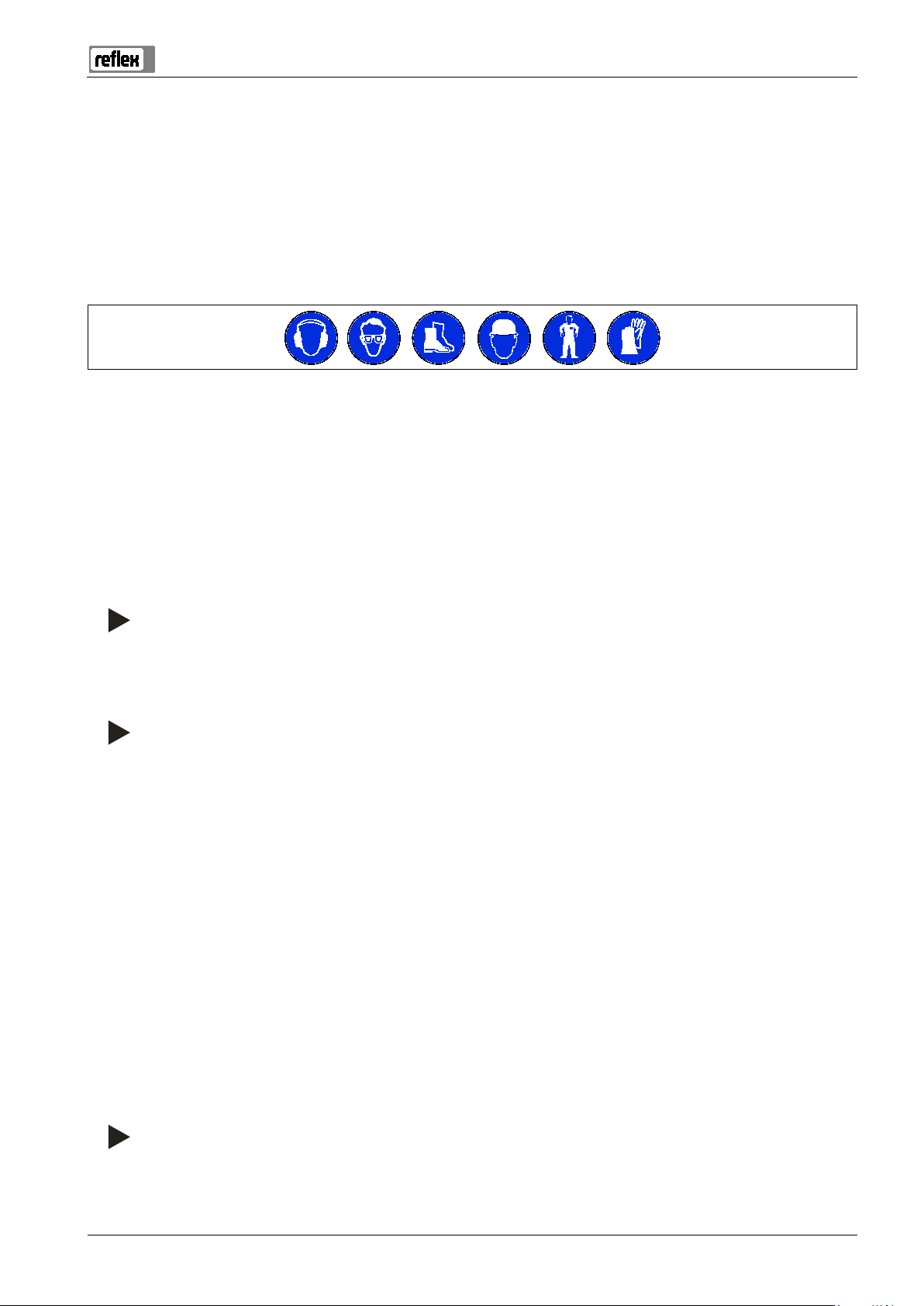
3.3 Personal protective equipment..........................................................................................................................................................7
3.4 Intended use..........................................................................................................................................................................................7
3.5 Inadmissible operating conditions.....................................................................................................................................................7
3.6 Residual risks .........................................................................................................................................................................................8
4Description of the device................................................................................................................................................................9
4.1 Description.............................................................................................................................................................................................9
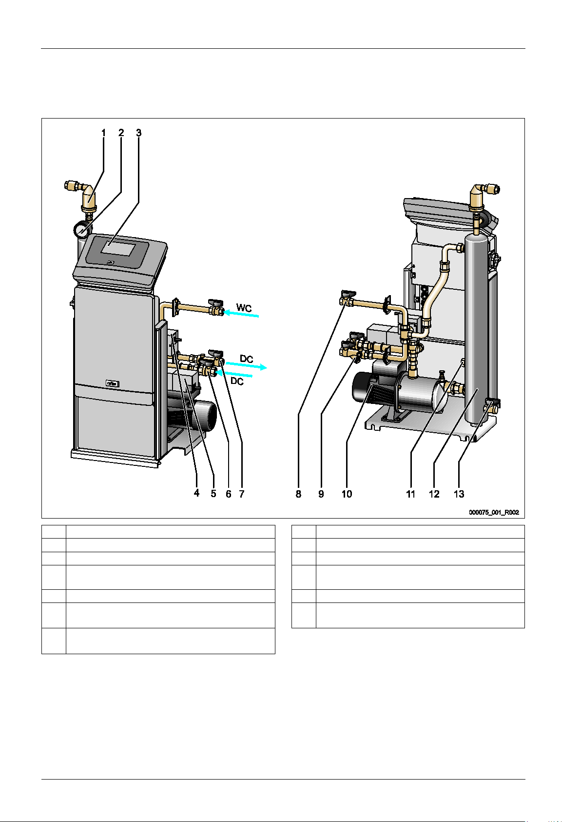
4.2 Overview ..............................................................................................................................................................................................10
4.3 Identification .......................................................................................................................................................................................13
4.3.1 Nameplate........................................................................................................................................................................13
4.3.2 Type code..........................................................................................................................................................................13
4.4 Function ...............................................................................................................................................................................................14
4.5 Scope of delivery.................................................................................................................................................................................17
4.6 Optional equipment and accessories ..............................................................................................................................................17
5Technical data ...............................................................................................................................................................................18
5.1 Electrical system..................................................................................................................................................................................18
5.2 Dimensions and connections............................................................................................................................................................18
5.3 Operation .............................................................................................................................................................................................19
6Installation.....................................................................................................................................................................................20
6.1 Installation conditions .......................................................................................................................................................................21
6.1.1 Incoming inspection .......................................................................................................................................................21
6.2 Preparatory work ................................................................................................................................................................................21
6.3 Execution..............................................................................................................................................................................................22
6.3.1 Fitting the add-on components....................................................................................................................................22
6.3.2 Floor mounting................................................................................................................................................................23
6.3.3 Wall mounting .................................................................................................................................................................23
6.3.4 Hydraulic connection......................................................................................................................................................24
6.4 Switching and make-up variants......................................................................................................................................................27
6.4.1 Pressure-dependent "Magcontrol" make-up mode...................................................................................................27
6.4.2 Level dependent "Levelcontrol" make-up mode .......................................................................................................28
6.5 Electrical connection ..........................................................................................................................................................................30
6.5.1 Terminal plan, connection component........................................................................................................................32
6.5.2 Terminal plan, operating unit........................................................................................................................................34
6.5.3 RS-485 interface...............................................................................................................................................................35
6.6 Installation and commissioning certificate.....................................................................................................................................35
7Commissioning..............................................................................................................................................................................36
7.1 Checking the requirements for commissioning.............................................................................................................................36
7.2 Setting the minimum operating pressure for Magcontrol...........................................................................................................37
7.3 Modifying the controller's start routine ..........................................................................................................................................39
7.4 Filling the device with water and venting ......................................................................................................................................39
7.5 Vacuum test.........................................................................................................................................................................................41
7.6 Hydraulic equalisation .......................................................................................................................................................................42
7.7 Use the device to fill the facility system with water......................................................................................................................45

Contents
4 — English Servitec 35-120 with Touch controller — 06.07.2016 - Rev. B
7.8 Setting the degassing programme in the Customer menu .........................................................................................................45
7.9 Parametrising the controller in the Customer menu ....................................................................................................................45
7.10 Starting Automatic mode..................................................................................................................................................................46
8Operation ...................................................................................................................................................................................... 47
8.1 Operating modes................................................................................................................................................................................47
8.1.1 Automatic mode..............................................................................................................................................................47
8.1.2 Manual mode...................................................................................................................................................................48
8.1.3 Stop mode........................................................................................................................................................................49
8.1.4 Summer operation..........................................................................................................................................................49
8.2 Restarting.............................................................................................................................................................................................50
9Controller...................................................................................................................................................................................... 51
9.1 Operator panel ....................................................................................................................................................................................51
9.2 Calibrating the touch screen.............................................................................................................................................................52
9.3 Modifying the controller's start routine..........................................................................................................................................53
9.4 Configuring settings in the controller .............................................................................................................................................56
9.4.1 Customer menu...............................................................................................................................................................56
9.4.2 Service menu....................................................................................................................................................................60
9.4.3 Default settings ...............................................................................................................................................................60
9.4.4 Degassing programmes – overview.............................................................................................................................61
9.4.5 Setting degassing programmes....................................................................................................................................62
9.5 Messages..............................................................................................................................................................................................64
10 Maintenance................................................................................................................................................................................. 67
10.1 Exterior leak test .................................................................................................................................................................................68
10.2 Cleaning ...............................................................................................................................................................................................69
10.2.1 Cleaning the dirt trap......................................................................................................................................................69
10.3 Function test........................................................................................................................................................................................70
10.4 Maintenance certificate.....................................................................................................................................................................71
10.5 Inspection ............................................................................................................................................................................................72
10.5.1 Pressure-bearing components......................................................................................................................................72
10.5.2 Inspection prior to commissioning...............................................................................................................................72
10.5.3 Inspection intervals.........................................................................................................................................................72
11 Disassembly.................................................................................................................................................................................. 73
12 Annex ............................................................................................................................................................................................ 74
12.1 Reflex Customer Service ....................................................................................................................................................................74
12.2 Conformity and standards.................................................................................................................................................................75
12.3 Certificate No. of the CE type test.....................................................................................................................................................76
12.4 Guarantee ............................................................................................................................................................................................76
Servi t ec 35 -120 with Touch controller
06.07.2016-Rev. B

Notes on the operating manual
Servitec 35-120 with Touch controller — 06.07.2016 - Rev. B English —
5
1Notes on the operating manual
This operating manual is an important aid for ensuring the safe and reliable functioning of the device.
The operating manual will help you to:
• avoid any risks to personnel.
• become acquainted with the device.
• achieve optimal functioning.
• identify and rectify faults in good time.
• avoid any faults due to improper operation.
• cut down on repair costs and reduce the number of downtimes.
• improve the reliability and increase the service life of the device.
• avoid causing harm to the environment.
Reflex Winkelmann GmbH accepts no liability for any damage resulting from failure to observe the information in this operating manual.
In addition to the requirements set out in this operating manual, national statutory regulations and provisions in the country of
installation must also be complied with (concerning accident prevention, environment protection, safe and professional work practices,
etc.).
This operating manual describes the device with basic equipment and interfaces for optional equipment with additional functions. For
optional equipment and accessories, see chapter 4.6 "Optional equipment and accessories" on page 17 .
Note!
Every person installing this equipment or performing any other work at the equipment is required to carefully read this
manual prior to commencing work and to comply with its instructions. The manual
is to be provided to the device operator
and must be stored near the device for access at any time.
2Liability and guarantee
The device has been built according to the state of the art and recognised safety rules. Nevertheless, its use can pose a risk to life and
limb of personnel or third persons as well as cause damage to the system or other property.
It is not permitted to make any modifications at the device, such as to the hydraulic system or the circuitry.
The manufacturer shall not be liable nor shall any warranty be honoured if the cause of any claim results from one or more of the
following causes:
• Improper use of the device.
• Unprofessional commissioning, operation, service, maintenance, repair or installation of the device.
• Failure to observe the safety information in this operating manual.
• Operation of the device with defective or improperly installed safety/protective equipment.
• Failure to perform maintenance and inspection work according to schedule.
• Use of unapproved spare parts or accessories.
Prerequisite for any warranty claims is the professional installation and commissioning of the device.
Note!
Arrange for Reflex Customer Service to carry out commissioning and annual mainten
ance, see chapter 12.1 "Reflex
Customer Service
" on page 74 .

Safety
6
— English Servitec 35-120 with Touch controller — 06.07.2016 - Rev. B
3Safety
3.1 Explanation of symbols
The following symbols and signal words are used in this operating manual.
DANGER
Danger of death and/or serious damage to health
• The sign, in combination with the signal word 'Danger', indicates imminent danger; failure to observe the safety information will
result in death or severe (irreversible) injuries.
WARNING
Serious damage to health
• The sign, in combination with the signal word 'Warning', indicates imminent danger; failure to observe the safety information can
result in death or severe (irreversible) injuries.
CAUTION
Damage to health
• The sign, in combination with the signal word 'Caution', indicates danger; failure to observe the safety information can result in
minor (reversible) injuries.
ATTENTION
Damage to property
• The sign, in combination with the signal word 'Attention', indicates a situation where damage to the product itself or objects within
its vicinity can occur.
Note!
This symbol, in combination with the signal word 'Note', indicates useful
tips and recommendations for efficient handling
of the product.

Safety
Servitec 35-120 with Touch controller — 06.07.2016 - Rev. B English —
7
3.2 Personnel requirements
Only specialist personnel or specifically trained personnel may install and operate the equipment.
The electric connections and the wiring of the device must be executed by a specialist in accordance with all applicable national and
local regulations.
3.3 Personal protective equipment
When working at the system, wear the stipulated personal equipment such as hearing and eye protection, safety boots, helmet,
protective clothing, protective gloves.
See the national regulation of your country for personal protective equipment required.
3.4 Intended use
The device is used in plant systems for stationary heating and cooling circuits. The devices may be used only in systems that are sealed
against corrosion and with the following water types:
• Non-corrosive.
• Chemically non-aggressive.
• Non-toxic.
Minimise the entry of atmospheric oxygen throughout the plant system and into the make-up water.
Note!
Ensure the quality of the make
-up water as specified by national regulations.
–
For example, VDI 2035 or SIA 384-1.
Note!
•
To ensure fault-free operation of the system for the long-term, glycols whose inhibitors prevent corrosion
phenomena must always be used for systems operating with water/glycol mixtures. It must also be ensured that no
foam is formed due to the substances in the water. Otherwise this could endanger the entire function of the vacuum
spray tube degassing as this can lead to sedimentation in the vent pipe and therefore leaks.
•
The specifications of the respective manufacturer are always decisive for the specific properties and mixing ratio of
the water/glycol mixtures.
•
Types of glycol must not be mixed and the concentration is generally to be checked every year (see manufacturer
information).
3.5 Inadmissible operating conditions
The device is not suitable for the following applications:
• Mobile system operation.
• Outdoor operation.
• For use with mineral oils.
• For use with flammable media.
• For use with distilled water.
Note!
It is not permitted to make any modifications to the hydraulic system or the circuitry.

Safety
8
— English Servitec 35-120 with Touch controller — 06.07.2016 - Rev. B
3.6 Residual risks
This device has been manufactured to the current state of the art. However, some residual risk cannot be excluded.
CAUTION
Risk of burns on hot surfaces
Hot surfaces in heating systems can cause burns to the skin.
• Wear protective gloves.
• Please place appropriate warning signs in the vicinity of the device.
CAUTION
Risk of injury due to pressurised liquid
If installation, removal or maintenance work is not carried out correctly, there is a risk of burns and other injuries at the connection
points, if pressurised hot water or hot steam suddenly escapes.
• Ensure proper installation, removal or maintenance work.
• Ensure that the system is de-pressurised before performing installation, removal or maintenance work at the connection points.
WARNING
Risk of injury due to heavy weight
The devices are heavy. Consequently, there is a risk of physical injury and accidents.
• Use suitable lifting equipment for transportation and installation.
CAUTION
Risk of injury upon coming into contact with glycol containing water
Contact with glycol containing water in plant systems for cooling circuits can result in irritation of the skin and eyes.
• Use personal protective equipment (safety clothing, gloves and goggles, for example).

Description of the dev
ice
Servitec 35-120 with Touch controller — 06.07.2016 - Rev. B English —
9
4Description of the device
4.1 Description
The device is a degassing and water make-up station for plant systems.
The following plant systems are applicable for the device:
• Plant systems with heating circuits.
• Plant systems with cooling circuits.
• Plant systems with solar circuits.
• Plant systems with process circuits.
The device fulfils two functions:
1. Degassing of water.
• Water from the plant system.
• Water from the make-up mains for the plant system.
It removes up to 90 % of the dissolved gases from the water. Operating faults in the plant system resulting from free or dissolved gases
in the water are avoided.
2. Make-up with water for the plant system.
• Two make-up variants can be selected for the plant system.
– Magcontrol make-up variant: For plant systems with diaphragm expansion tanks.
– Levelcontrol make-up variant: For plant systems with pressure maintaining stations.
The device provides the following safety features:
• Control of the pressure maintenance of the plant system
• Automatic make-up with water.
• No water circulation problems in the plant system.
• Reduction of corrosion damage by removal of oxygen from the water.
Note!
The device can only be operated at water temperatures up to a maximum of 90
°C.

Description of the device
10
— English Servitec 35-120 with Touch controller — 06.07.2016 - Rev. B
4.2 Overview
The unit overviews are only examples. Structure and functionality is the same for the devices below.
Servitec 35 and Servitec 60(gl)
1 "DV" degassing valve 8 Make-up to degassing connection
2 "PI" vacuum gauge 9 "ST" dirt trap
3 Control Touch controller 10 "PU“ horizontal pump
4 "CD" 3-ways motor control valve upstream of vacuum
spray tube
11 Insufficient water switch
5 "CD" 2-ways motor ball valve downstream of "PU" pump 12 "VT" vacuum spray tube
6 Connection for degassing
• Gas-rich water inlet
13 "FD" feed and drain cock
7 Connection for degassing
• Degassed water outlet

Description of the device
Servitec 35-120 with Touch controller — 06.07.2016 - Rev. B English —
11
Servitec 75 ad Servitec 95
1 Control Touch controller 7 "PU“ vertical pump
2 "PI" vacuum gauge 8 "CD" 2-ways motor ball valve downstream of "PU" pump
3 "DV" degassing valve 9 Connection for degassing
• Degassed water outlet
4 "CD" 3-ways motor control valve upstream of vacuum
spray tube
10 Degassed water pump connection
5 Make-up to degassing connection 11 Feed and drain cock
6 Connection for degassing
• Gas-rich water inlet

Description of the device
12
— English Servitec 35-120 with Touch controller — 06.07.2016 - Rev. B
Servitec 75(gl), Servitec 95(gl), Servitec 120 (gl) and Servitec 90° models with mechanical actuators.
1 Optional "GV" solenoid valve of the "DC" degassing line
• Only with Servitec 75gl, Servitec 95gl and
Servitec 120 gl
7 "PI" vacuum gauge
2 "PU“ vertical pump 8 Feed and drain cock
3 "CDp" overflow valve of the "DC" degassing line
• For degassed water to the system
9 Suction line of the "VT" vertical pump
4 Control Touch controller 10 "CDs" pressure-reducing valve of the "DC" degassing line
• For gas-rich water from the system
5 "VT" vacuum spray tube 11 "CDw" pressure-reducing valve of the "WC“ make-up line
6 "VT" vacuum spray tube 12 "GV" solenoid valve of the "DC" degassing line

Description of the device
Servitec 35-120 with Touch controller — 06.07.2016 - Rev. B English —
13
4.3 Identification
4.3.1 Nameplate
The nameplate provides information about the manufacturer, the year of manufacture, the manufacturing number and the technical
data.
Information on nameplate
Meaning
Type Device name
Serial No. Serial number
min. / max. allowable pressure P Minimum/maximum
permissible pressure
max. continuous operating
temperature
Maximum temperature for
continuous operation
min. / max. allowable temperature
/ flow temperature TS
Minimum / maximum
permissible temperature /
TS flow temperature
Year built Year of manufacture
min. operating pressure set up on
shop floor
Factory-set minimum
operating pressure
at site Set minimum operating
pressure
max. pressure saftey valve factory -
aline
Factory-set opening
pressure of the safety
valve
at site Set opening pressure of
the safety valve
4.3.2 Type code
No.
Type code (example)
1 Device name
2 Pump head height Servitec 35 Touch
3 Controller type 1 2 3

Description of the device
14
— English Servitec 35-120 with Touch controller — 06.07.2016 - Rev. B
4.4 Function
The device combines the functions make-up and degassing of water for the plant system:
• Gas-rich water is conveyed via the make-up line connection from the plant system to the vacuum spray tube.
• Additional freshwater is conveyed via the make-up line connection from the plant system to the vacuum spray tube.
A freshwater make-up occurs if there is a pressure drop in the plant system.
Sequence of a degassing cycle in the vacuum spray tube
1 Create vacuum in the spray tube 3 Discharge
2 Injection 4 Idling time
The degassing operation uses timer-controlled cycles. A cycle comprises the following phases:
1. Create vacuum in the spray tube.
– The pump starts and conveys water from the vacuum spray tube The pump transports more water from the spray tube than
can be transported via the connection lines of the water make-up. A vacuum is created.
2. Injection
– Opening of the solenoid valves in the make-up lines routes gas-rich water into the spray tube. It is atomised by nozzles in the
spray tube. The atomised water is degassed in the vacuum of the spray tube because of the large surface area resulting from
the atomisation. The degassed water is returned to the plant system via the vacuum pump. The overflow valve means that the
pump is set to a constant working pressure. The working pressure depends on the respective plant system.
3. Discharge
– The pump shuts down. The pressure in the plant system causes more water to be injected into the vacuum spray tube and
degassed. The water level in the vacuum spray tube rises. The gases released in the vacuum spray tube are released into the
ambient atmosphere via the degassing valves.
4. Idling time
– When the gas has been discharged, the device will remain in idle until the next cycle is started. Post-degassing occurs during
the idling time.

Description of the device
Servitec 35-120 with Touch controller — 06.07.2016 - Rev. B English —
15
Degassing programmes
The device controller regulates the degassing process. The controller monitors the operating states and outputs them to the display.
The controller provides 3 different degassing programmes for selection and adjustment:
• Continuous degassing
– For continued degassing over several hours or days in a sequence of degassing cycles without idling periods. This degassing
programme must be selected after commissioning and repairs.
• Interval degassing
– This comprises a limited number of degassing cycles. The system idles between the intervals. This degassing programme must
be selected for continuous operation.
• Make-up degassing
– Is automatically activated for every water make-up during continuous or interval degassing. The sequence corresponds to
continuous degassing. The degassing time is limited by the make-up time.
Make-up variants
There are two make-up variants for the device. These are selected in the controller and set for the device:
• Magcontrol make-up variant.
– For plant systems with diaphragm expansion tanks. The pressure in the plant system is monitored with the aid of the
integrated pressure sensor in the device. If the plant pressure falls below the calculated filling pressure, water make-up is
triggered.
• Levelcontrol make-up variant:
– For plant systems with pressure maintaining stations. The water level in the expansion tank of the pressure maintaining system
is determined with the "LIS" external pressure transducer. If the water level falls in the expansion tank, a signal is triggered at
the device controller to start the water make-up.
Servitec 35 - 95 with motor ball valve
1 Signal line from the "LIS" level sensor for the
"Levelcontrol" make-up variant
5 "WC" make-up line
2 Signal line from the "PIS" pressure transducer for the
"Magcontrol" make-up variant
6 For optional equipment and accessories see chapter 4.6
"Optional equipment and accessories" on page 17
3 "DC" degassing line (degassed water) 7 Control Touch controller
4
"DC" degassing line (gas-rich water)

Description
of the device
16
— English Servitec 35-120 with Touch controller — 06.07.2016 - Rev. B
Servitec 75 -95 and 120 with mechanical actuators
1 "DC" degassing line (degassed water) 4 For optional accessories, see chapter 4.6 "Optional
equipment and accessories" on page 17
2 "DC" degassing line (gas-rich water) 6 Control Touch controller
3
"WC" make-up line

Description of the device
Servitec 35-120 with Touch controller — 06.07.2016 - Rev. B English—
17
4.5 Scope of delivery
The scope of delivery is described in the shipping document and the content is shown on the packaging.
Immediately after receipt of the goods, please check the shipment for completeness and damage. Please notify us immediately of any
transport damage.
Basic degassing equipment:
• Device controller.
• "DV" degassing valve, box-packaged.
• Plastic sleeve with operating manual and electric wiring diagram (attached to the device).
The device is pre-assembled and shipped on a pallet.
4.6 Optional equipment and accessories
The following optional equipment and accessories are available for this device:
• Fillset or Fillset Compact for make-up with water.
– Fillset or Fillset Compact with integrated system separator, water meter, dirt trap, and locking mechanisms for the "WC" make-
up line.
• Fillsoft/Fillsoft zero for softening/desalinating the make-up water from the public water network.
– Fillsoft/Fillsoft zero is installed between Fillset and the device. The device controller evaluates the make-up quantities and
signals a required replacement of the softening and desalination cartridges.
• Enhancements for the device controller.
– Use the RS-485 interface to retrieve various data from the controller and to communicate with control centres or other devices
see chapter 6.5.3 "RS-485 interface" on page 35 .. You need the following items for the communication of the RS-485 interface
with control centres or other devices:
• Bus modules for the communication with control centres.
• Lonworks Digital.
• Lonworks.
• Profibus-DP.
• Ethernet.
• I/O module for standard communication.
• Modbus RTU
• Gas discharge measurement for an optimised degassing operation.
Note!
Separate operating instructions are supplied with accessories.

Technical data
18
— English Servitec 35-120 with Touch controller — 06.07.2016 - Rev. B
5Technical data
Note!
The following values apply for all systems:
–
Permissible flow temperature:
–
Permissible inlet pressure for make-up:
–
Make-up capacity:
–
Separation level, dissolved gases:
–
Separation level, free gases:
–
Degree of protection:
120 °C
1.3 bar – 6 bar
0.55 m³/h
≤ 90 %
100 %
IP 54
5.1 Electrical system
Type
Power output
(kW)
Power supply
(V / Hz)
Fusing
(A)
Number of RS-
485 interfaces
I/O module
Electrical voltage
control unit
(V, A)
Noise level
(dB)
35 0.85 230 / 50 10 2 Optional 230, 2 55
60 1.1 230 / 50 10 2 Optional 230, 2 55
Opt
60 GL
1.1
230 / 50
10
2
Optional
230, 2
55
ional
75 1.1 230 / 50 10 2 Optional 230, 2 55
75 GL 1.1 230 / 50 10 2 Optional 230, 2 55
95 1.1 230 / 50 10 2 Optional 230, 2 55
95 GL 1.1 230 / 50 10 2 Optional 230, 2 55
120 1.5 400 / 50 10 2 Optional 230, 2 55
120 GL 1.5 400 / 50 10 2 Optional 230, 2 55
5.2 Dimensions and connections
Type
Weight
(kg)
Height
(mm)
Width
(mm)
Depth
(mm)
Degassing
device
connection
Degassing
system
connection
Make-up
connection
35 30 1030 620 440 IG ½ " Internal thread
1 "
IG ½ "
60 36 1215 685 440 IG ½ " Internal thread
1 "
IG ½ "
60 GL 36 1215 685 440 IG ½ " Internal thread
1 "
IG ½ "
75 41 1215 600 525 IG ½ " Internal thread
1 "
IG ½ "
75 GL 41 1215 600 525 IG ½ " Internal thread
1 "
IG ½ "
95 42 1215 600 525 IG ½ " Internal thread
1 "
IG ½ "
95 GL 42 1215 600 525 IG ½ " Internal thread
1 "
IG ½ "
120 43 1215 600 525 IG ½ " Internal thread
1 "
IG ½ "
120 GL 43 1215 600 525 IG ½ " Internal thread
1 "
IG ½ "

Technical data
Servitec 35-120 with Touch controller — 06.07.2016 - Rev. B English —
19
5.3 Operation
Type
System volume
(100% water)
(m³)
System volume
(50% water)
(m³)
Working
pressure
(bar)
Permissible operating
gauge pressure
(bar)
Setpoint overflow
valve
(bar)
Operating
temperature
(°C)
35 220 – 0.5 – 2.5 8 – >0 – 70
60 220 – 0.5 – 4.5 8 – >0 – 70
60 GL – 50 0.5 – 4.5 8 4.7 >0 – 70
75 220 – 0.5 – 5.4 10 – >0 – 70
75 GL – 50 0.5 – 5.4 10 5.7 >0 – 70
95 220 – 0.5 – 7.2 10 – >0 – 70
95 GL – 50 0.5 – 7.2 10 7.9 >0 – 70
120 220 – 1.3 – 9 10 – >0 – 70
120 GL – 50 1.3 – 8.3 10 9.7 >0 – 70
Approximate values for the maximal "Va" system volume to be degassed under extreme conditions during commissioning at a nitrogen
reduction from 18 mg/l to 10 mg/l.
1 Continuous degassing "t" [h] 2 System volume "Va" [m3]

Installation
20
— English Servitec 35-120 with Touch controller — 06.07.2016 - Rev. B
6Installation
DANGER
Risk of serious injury or death due to electric shock.
If live parts are touched, there is risk of life-threatening injuries.
• Ensure that the system is voltage-free before installing the device.
• Ensure that the system is secured and cannot be reactivated by other persons.
• Ensure that installation work for the electric connection of the device is carried out by an electrician, and in compliance with
electrical engineering regulations.
CAUTION
Risk of injury due to pressurised liquid
If installation, removal or maintenance work is not carried out correctly, there is a risk of burns and other injuries at the connection
points, if pressurised hot water or hot steam suddenly escapes.
• Ensure proper installation, removal or maintenance work.
• Ensure that the system is de-pressurised before performing installation, removal or maintenance work at the connection points.
CAUTION
Risk of burns on hot surfaces
Hot surfaces in heating systems can cause burns to the skin.
• Wear protective gloves.
• Please place appropriate warning signs in the vicinity of the device.
CAUTION
Risk of injury due to falls or bumps
Bruising from falls or bumps on system components during installation.
• Wear personal protective equipment (helmet, protective clothing, gloves, safety boots).
Note!
Confirm that installation and start
-up have been carried out correctly using the installation, start-up and maintenance
certificate. This action is a prerequisite for the making of warranty claims.
–
Have the Reflex Customer Service carry out commissioning and the annual maintenance.
Table of contents
Other Reflex Industrial Equipment manuals

Reflex
Reflex Reflexomat Installation instructions

Reflex
Reflex Reflexomat RS 90/1 User manual

Reflex
Reflex Exdirt Magneto Installation instructions

Reflex
Reflex Storatherm HF R2 Series Installation instructions

Reflex
Reflex Servitec 35-95 User manual

Reflex
Reflex Servimat M Installation instructions

Reflex
Reflex REFLEXOMAT RG User manual

Reflex
Reflex Refix DD Series User manual

Reflex
Reflex Servitec 35 User manual

Reflex
Reflex Fillcontrol Auto User manual