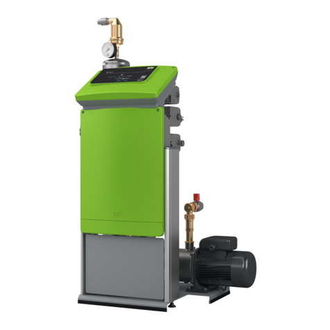
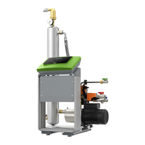
Reflex Fillcontrol Plus Compact Installation instructions

Fillcontrol Plus Compact 03.05.2022 - Rev. D
DE
Originalbetriebsanleitung
EN
Original operating manual
FR
Mode d’emploi original
ES
Manual de instrucciones original
PT
Manual de instruções original
IT
Istruzioni per l'uso originali
HU
Eredeti üzemeltetési utasítás
SL
Izvirna navodila za obratovanje
SK
Originálny návod na obsluhu
CS
Originální návod k obsluze
LT
Oriģinālā lietošanas pamācība
NL
Originele bedieningshandleiding
DA
Original brugsvejledning
NO
Original bruksanvisning
SE
Originaldriftsinstruktioner
FI
Alkuperäinen käyttöohje
RU
Перевод оригинального
руководства
RO
Instrucţiuni de utilizare originale
TR
Orijinal kullanım kılavuzu
EL
Πρωτότυποεγχειρίδιο
λειτουργίας

Inhaltsverzeichnis
2 — Deutsch Fillcontrol Plus Compact — 03.05.2022 - Rev. D
Deutsch............................................................................................ 3
English........................................................................................... 11
Français.......................................................................................... 19
Español .......................................................................................... 28
Português...................................................................................... 37
Italiano........................................................................................... 45
Magyar........................................................................................... 54
Slovenščina.................................................................................... 62
Slovensky....................................................................................... 70
Česky.............................................................................................. 78
Latviski........................................................................................... 86
Nederlands .................................................................................... 94
Dansk........................................................................................... 102
Norsk............................................................................................ 110
Svenska........................................................................................ 118
Suomi........................................................................................... 126
Русский...................................................................................... 134
Română ....................................................................................... 144
Türk.............................................................................................. 153
Ελληνικά.................................................................................... 161

Inhaltsverzeichnis
Fillcontrol Plus Compact — 03.05.2022 - Rev. D
Deutsch —
3
Inhaltsverzeichnis
deuts ch
1Hinweise zur Betriebsanleitung ...............................................4
2Haftung und Gewährleistung...................................................4
3Sicherheit...................................................................................4
3.1 Symbolerklärung.....................................................................................4
3.1.1 Hinweise in der Anleitung .....................................................4
3.2 Anforderungen an das Personal ............................................................ 4
3.3 Persönliche Schutzausrüstung............................................................... 4
3.4 Bestimmungsgemäße Verwendung ..................................................... 4
3.5 Unzulässige Betriebsbedingungen........................................................ 4
3.6 Restrisiken................................................................................................4
4Gerätebeschreibung .................................................................5
4.1 Beschreibung ...........................................................................................5
4.2 Übersichtsdarstellung.............................................................................5
4.3 Identifikation............................................................................................5
4.3.1 Typenschild ............................................................................. 5
4.4 Lieferumfang............................................................................................5
4.5 Optionale Zusatzausrüstung..................................................................5
5Technische Daten......................................................................5
6Montage ....................................................................................6
6.1 Montagevoraussetzungen......................................................................6
6.1.1 Prüfung des Lieferzustandes................................................. 6
6.2 Vorbereitungen .......................................................................................6
6.3 Durchführung .......................................................................................... 6
6.4 Schaltschema........................................................................................... 6
6.5 Elektrischer Anschluss............................................................................. 7
6.5.1 Klemmenplan ......................................................................... 7
7Erstinbetriebnahme ................................................................. 7
7.1 Voraussetzungen für die Inbetriebnahme............................................ 7
7.2 Mindestbetriebsdruck P0für Steuerung ermitteln .............................. 7
7.2.1 Mindestbetriebsdruck in die Steuerung eingeben............. 8
7.2.2 Druckminderer einstellen...................................................... 8
7.2.3 Anlage mit Wasser füllen....................................................... 8
7.2.4 Schmutzfänger reinigen........................................................ 8
8Betrieb....................................................................................... 8
8.1 Betriebsarten........................................................................................... 8
8.1.1 Automatikbetrieb................................................................... 8
8.1.2 Notschließfunktion ................................................................ 8
8.2 Werkseinstellungen im Servicemenü ................................................... 9
8.3 Störmeldungen ....................................................................................... 9
9Wartung.................................................................................... 9
10 Demontage............................................................................. 10
11 Anhang.................................................................................... 10
11.1 Reflex-Werkskundendienst.................................................................. 10
11.2 Konformität / Normen.......................................................................... 10
11.3 Gewährleistung..................................................................................... 10
ivz_de
Deuts ch
03.05.2022-Rev. D

Hinweise zur Betriebsanleitung
4 — Deutsch Fillcontrol Plus Compact — 03.05.2022 - Rev. D
1Hinweise zur Betriebsanleitung
Diese Betriebsanleitung ist eine wesentliche Hilfe zur sicheren und
einwandfreien Funktion des Gerätes.
Für Schäden, die durch Nichtbeachtung dieser Betriebsanleitung entstehen,
übernimmt die Firma Reflex Winkelmann GmbH keine Haftung. Zusätzlich zu
dieser Betriebsanleitung sind die nationalen gesetzlichen Regelungen und
Bestimmungen im Aufstellungsland einzuhalten (Unfallverhütung,
Umweltschutz, sicherheits- und fachgerechtes Arbeiten etc.).
Diese Betriebsanleitung beschreibt das Gerät mit einer Grundausrüstung und
Schnittstellen für eine optionale Zusatzausrüstung mit zusätzlichen Funktionen.
Hinweis!
Di
ese Anleitung ist von jeder Person, die diese Geräte montiert oder
andere Arbeiten am Gerät durchführt, vor dem Gebrauch sorgfältig zu
lesen und anzuwenden. Die Anleitung ist dem Betreiber des Gerätes
auszuhändigen und von diesem griffbereit in der Nähe de
s Gerätes
aufzubewahren.
2Haftung und Gewährleistung
Das Gerät ist nach dem Stand der Technik und anerkannten
sicherheitstechnischen Regeln gebaut. Dennoch können bei der Verwendung
Gefahren für Leib und Leben des Personals bzw. Dritter sowie
Beeinträchtigungen an der Anlage oder an Sachwerten entstehen.
Es dürfen keine Veränderungen, wie zum Beispiel an der Hydraulik oder Eingriffe
in die Verschaltung an dem Gerät vorgenommen werden.
Die Haftung und Gewährleistung des Herstellers ist ausgeschlossen, wenn sie auf
eine oder mehrere Ursachen zurückzuführen sind:
• Nicht bestimmungsgemäße Verwendung des Gerätes.
• Unsachgemäße Inbetriebnahme, Bedienung, Wartung, Instandhaltung,
Reparatur und Montage des Gerätes.
• Nicht Beachten der Sicherheitshinweise in dieser Betriebsanleitung.
• Betreiben des Gerätes bei defekten oder nicht ordnungsgemäß
angebrachten Sicherheitseinrichtungen / Schutzvorrichtungen.
• Nicht fristgerechte Durchführung der Wartungs- und Inspektionsarbeiten.
• Verwendung von nicht freigegebenen Ersatz- und Zubehörteilen.
Voraussetzung für Gewährleistungsansprüche ist die fachgerechte Montage und
Inbetriebnahme des Gerätes.
Hinweis!
Lassen Sie d
ie erstmalige Inbetriebnahme sowie die jährliche Wartung
durch den Reflex
-Werkskundendienst durchführen, 11.1 "Reflex-
Werkskundendienst", 10.
3Sicherheit
3.1 Symbolerklärung
3.1.1 Hinweise in der Anleitung
Die folgenden Hinweise werden in der Betriebsanleitung verwendet.
GEFAHR
Lebensgefahr / Schwere gesundheitliche Schäden
• Der Hinweis in Verbindung mit dem Signalwort „Gefahr“ kennzeichnet
eine unmittelbar drohende Gefahr, die zum Tod oder zu schweren
(irreversiblen) Verletzungen führt.
WARNUNG
Schwere gesundheitliche Schäden
• Der Hinweis in Verbindung mit dem Signalwort „Warnung“
kennzeichnet eine drohende Gefahr, die zum Tod oder zu schweren
(irreversiblen) Verletzungen führen kann.
VORSICHT
Gesundheitliche Schäden
• Der Hinweis in Verbindung mit dem Signalwort „Vorsicht“
kennzeichnet eine Gefahr, die zu leichten (reversiblen) Verletzungen
führen kann.
ACHTUNG
Sachschäden
• Der Hinweis in Verbindung mit dem Signalwort „Achtung“
kennzeichnet eine Situation, die zu Schäden am Produkt selbst oder an
Gegenständen in seiner Umgebung führen kann.
Hinweis!
Dieses Symbol in Verbindung mit dem Signalwort „Hinweis“
kennzeichnet
nützliche Tipps und Empfehlungen für den effizienten
Umgang mit dem Produkt.
3.2 Anforderungen an das Personal
Montage, Inbetriebnahme und Wartung sowie Anschluss der elektrischen
Komponenten nur durch sachkundiges und entsprechend qualifiziertes
Fachpersonal.
3.3 Persönliche Schutzausrüstung
Tragen Sie bei allen Arbeiten an der Anlage die vorgeschriebene persönliche
Schutzausrüstung, z. B. Gehörschutz, Augenschutz, Sicherheitsschuhe,
Schutzhelm, Schutzkleidung, Schutzhandschuhe.
Angaben über die persönliche Schutzausrüstung befinden sich in den nationalen
Vorschriften des jeweiligen Betreiberlandes.
3.4 Bestimmungsgemäße Verwendung
Das Gerät ist eine Nachspeisestation für Heiz- und Kühlwassersysteme mit
Membran-Druckausdehnungsgefäßen. Es dient zum Halten von Wasserdruck
und zum Nachspeisen von Wasser in einem Anlagensystem. Der Betrieb darf nur
in Anlagensystemen mit einer statischen Druckhaltung und in
korrosionstechnisch geschlossenen Systemen mit folgenden Wassern erfolgen:
• Nicht korrosiv
• Chemisch nicht aggressiv
• Nicht giftig
Der Zutritt von Luftsauerstoff durch Permeation in das gesamte Heiz- und
Kühlwassersystem, Nachspeisewasser usw. ist im Betrieb zuverlässig zu
minimieren.
3.5 Unzulässige Betriebsbedingungen
Das Gerät ist für die folgenden Bedingungen nicht geeignet:
• In mobilen Anlagenbetrieb.
• Für den Außeneinsatz.
• Für den Einsatz mit Mineralölen.
• Für den Einsatz mit entflammbaren Medien.
• Für den Einsatz mit destilliertem Wasser.
Hinweis!
Veränderungen an der Hydraulik oder Eingriffe in die Verschaltung sind
unzulässig.
3.6 Restrisiken
Dieses Gerät ist nach dem aktuellen Stand der Technik hergestellt. Trotzdem
lassen sich Restrisiken nie ausschließen.
VORSICHT
Verbrennungsgefahr an heißen Oberflächen
In Heizungsanlagen kann es durch hohe Oberflächentemperaturen zu
Verbrennungen der Haut kommen.
• Tragen Sie Schutzhandschuhe.
• Bringen Sie entsprechende Warnhinweise in der Nähe des Gerätes an.
Gerätebeschreibung
Fillcontrol Plus Compact — 03.05.2022 - Rev. D
Deutsch —
5
VORSICHT
Verletzungsgefahr durch unter Druck austretende Flüssigkeit
An den Anschlüssen kann es bei fehlerhafter Montage, Demontage oder
Wartungsarbeiten zu Verbrennungen und Verletzungen kommen, wenn
heißes Wasser oder heißer Dampf unter Druck plötzlich herausströmt.
• Stellen Sie eine fachgerechte Montage, Demontage oder
Wartungsarbeit sicher.
• Stellen Sie sicher, dass die Anlage drucklos ist, bevor Sie Montage,
Demontage oder Wartungsarbeiten an den Anschlüssen durchführen.
4Gerätebeschreibung
4.1 Beschreibung
Das Gerät ermöglicht eine kontrollierte und nach DIN EN 1717 geforderte sichere
Befüllung und Nachspeisung von Heiz- und Kühlwassersystemen mit
Frischwasser aus dem Trinkwassernetz. Der eingebaute Systemtrenner „BA“
(nach DIN EN 12729) verhindert das Rückfließen von Anlagenwasser aus den
Heiz- bzw. Kühlwassersystemen in das Trinkwassernetz. Das Gerät ist für den
Anschluss zwischen dem Trinkwassernetz und den Heiz- bzw.
Kühlwassersystemen nach DIN EN 12828 zugelassen.
4.2 Übersichtsdarstellung
1 Absperrung 5 Manometer
2 Motokugelhahn 6 Druckminderer
3 Drucksensor 7 Systemtrenner
4 Steuerung/Bedienfeld 8 Verschluss vom Systemtrenner
Das Gerät besteht aus einer Absperrarmatur, einem Systemtrenner, einem
Schmutzfänger, einem Drucksensor, einem Motorkugelhahn, einem
Druckminderer mit Kontrollmanometer und einer Steuerung. Der Einstellbereich
des Druckminderers liegt zwischen 0,5 und 5 bar.
Das Gehäuse besteht aus Pressmessing. Die Innenteile und Ablauftrichter
bestehen aus hochwertigem Kunststoff und Elastomer (EPDM).
4.3 Identifikation
4.3.1 Typenschild
Dem Typenschild entnehmen Sie Angaben zum Hersteller, zum Baujahr, zur
Herstellnummer sowie zu den technischen Daten.
Eintrag auf dem Typenschild
Bedeutung
Type Gerätebezeichnung
Serial No. Seriennummer
Min. / max. allowable pressure PS Minimaler / Maximaler zulässiger Druck
Max. allowable flow temperature of
system
Maximal zulässige Vorlauftemperatur
des Systems
Min. / max. working temperature
TS
Min. / max. Betriebstemperatur (TS)
Year of manufacture
Herstelljahr
Max. system pressure Max. Systemdruck
Min. operating pressure set up on
site
Mindestbetriebsdruck bauseits
eingestellt
4.4 Lieferumfang
Der Lieferumfang wird auf dem Lieferschein beschrieben und der Inhalt auf der
Verpackung angezeigt.
Grundausrüstung zur Nachspeisearmatur:
• Das Gerät
• Betriebsanleitung
• Netzteil
• Anschlussverschraubung
• Manometer
4.5 Optionale Zusatzausrüstung
Folgende Zusatzausrüstungen sind für das Gerät erhältlich:
• Kontaktwasserzähler „FQIRA+“.
• Enthärtung mit Reflex „Fillsoft“.
• Drucksensor Reflex „FE“
Hinweis!
Mit den Zusatzausrüstungen
werden separate Betriebsanleitungen
ausgeliefert.
5Technische Daten
Zulässige Umgebungstemperatur > 0 – 45 °C
Schutzgrad IP 54
Schallpegel 55 dB
Elektrische Leistung 350 W
Elektrischer Anschluss 230 V / 50 Hz (2 m
Anschlusskabel mit Netzteil und
Stecker)
Absicherung 4 A
Gewicht 3,0 kg
Höhe 304 mm
Breite 240 mm
Tiefe
91 mm
Anschluss Eintritt RP ½“
Anschluss Austritt RP ½“
Nachspeiseleistung ≤ 500 l/h
Max. Zulaufdruck 10 bar
Min. Zulaufdruck P0+ 1,3 bar
Max. Förderdruck ≤ 1,5 bar
Zulässiger Betriebsüberdruck 10 bar
Zulässige Betriebstemperatur 70 °C
Durchflussmedium Trinkwasser
Zul. min. Betriebsdruck p01 - 4,5 bar (1,5 bar
voreingestellt)
Ausgangsdruck (Druckminderer) 0,5 - 5 bar (3,0 bar
voreingestellt)
Potenzialfreier Ausgang (Wechsler) für Sammelstörmeldung, max.
Kontaktbelastung 230 V, 2 A

Montage
6 — Deutsch Fillcontrol Plus Compact — 03.05.2022 - Rev. D
6Montage
GEFAHR
Lebensgefährliche Verletzungen durch Stromschlag.
Bei Berührung stromführender Bauteile entstehen lebensgefährliche
Verletzungen.
• Stellen Sie sicher, dass die Anlage, in der das Gerät montiert wird,
spannungsfrei geschaltet ist.
• Stellen Sie sicher, dass die Anlage durch andere Personen nicht wieder
eingeschaltet werden kann.
• Stellen Sie sicher, dass Montagearbeiten am elektrischen Anschluss des
Gerätes nur durch eine Elektrofachkraft und nach elektrotechnischen
Regeln durchgeführt werden.
VORSICHT
Verletzungsgefahr durch unter Druck austretende Flüssigkeit
An den Anschlüssen kann es bei fehlerhafter Montage, Demontage oder
Wartungsarbeiten zu Verbrennungen und Verletzungen kommen, wenn
heißes Wasser oder heißer Dampf unter Druck plötzlich herausströmt.
• Stellen Sie eine fachgerechte Montage, Demontage oder
Wartungsarbeit sicher.
• Stellen Sie sicher, dass die Anlage drucklos ist, bevor Sie Montage,
Demontage oder Wartungsarbeiten an den Anschlüssen durchführen.
VORSICHT
Verbrennungsgefahr an heißen Oberflächen
In Heizungsanlagen kann es durch hohe Oberflächentemperaturen zu
Verbrennungen der Haut kommen.
• Tragen Sie Schutzhandschuhe.
• Bringen Sie entsprechende Warnhinweise in der Nähe des Gerätes an.
VORSICHT
Verletzungsgefahr durch Stürze oder Stöße
Prellungen durch Stürze oder Stöße an Anlagenteilen während der Montage.
• Tragen Sie persönliche Schutzausrüstung (Schutzhelm, Schutzkleidung,
Schutzhandschuhe, Sicherheitsschuhe).
Hinweis!
Bestätigen Sie die fachgerechte Montage und Inbetriebnahme in der
Montage
-, Inbetriebnahme- und Wartungsbescheinigung. Dies ist die
Voraussetzung für Gewährleistungsansprüche.
–
Lassen Sie die erstmalige Inbetriebnahme und die jährliche
Wartung durch den Reflex-Werkskundendienst durchführen.
• Angaben zum Hersteller, Baujahr, Herstellernummer sowie technische
Daten entnehmen Sie dem Typenschild bzw. den Markierungen auf der
Armatur. Beachten Sie, dass die Betriebsparameter für die Temperatur-
und Druckabsicherung weder über-, noch unterschritten werden.
• Das Gerät wird mit einem Stecker (Netzteil) ausgeliefert und darf nur an
einer geerdeten Schutzkontaktsteckdose angeschlossen werden.
6.1 Montagevoraussetzungen
6.1.1 Prüfung des Lieferzustandes
Das Gerät wird vor der Auslieferung sorgfältig geprüft und verpackt.
Beschädigungen während des Transportes können nicht ausgeschlossen
werden.
Gehen Sie wie folgt vor:
1. Prüfen Sie nach dem Wareneingang die Lieferung.
• Auf Vollständigkeit.
• Auf mögliche Beschädigungen durch den Transport.
2. Dokumentieren Sie die Beschädigungen.
3. Kontaktieren Sie den Spediteur, um den Schaden zu reklamieren.
6.2 Vorbereitungen
• Der Einbauort muss ein frostfreier und gut durchlüfteter Raum sein, der vor
Überflutung geschützt ist.
• Halten Sie einen ausreichenden Abstand des Gerätes zur Wand ein.
• Das Gerät muss für die Wartung, Montage und Demontage zugänglich
sein.
6.3 Durchführung
ACHTUNG
Schäden durch unsachgemäße Montage
durch Anschlüsse von Rohrleitungen oder durch Apparate der Anlage
können zusätzliche Belastungen des Gerätes entstehen.
• Stellen Sie eine spannungs- und schwingungsfreie (momentenfreie)
Montage der Rohranschlüsse des Gerätes zur Anlage sicher.
• Sorgen Sie bei Bedarf für eine Abstützung der Rohrleitungen oder
Apparate.
Montieren Sie das Gerät an das Anlagensystem.
Gehen Sie bei der Montage wie folgt vor:
1. Verlegen Sie die entsprechende Anschlussleitung vom Trinkwassernetz
zum Gerät.
– Beachten Sie, dass keine Stagnation im Wasserkreislauf entsteht.
2. Verlegen Sie die ausgangsseitige Leitung vom Gerät zum Anlagensystem.
– Wählen Sie eine entsprechende Dimension (Länge / Durchmesser)
für die ausgangsseitige Leitung des Gerätes.
– Beachten Sie, dass der Druckverlust in dieser Leitung in jedem
Betriebszustand < 0,3 bar ist.
3. Spülen Sie nach der Verlegung die Leitungen sorgfältig aus.
– Beschädigungen durch Verunreinigungen werden somit vermieden.
4. Beachten Sie die richtige Flussrichtung des Gerätes.
– Beachten Sie die Markierung der Flussrichtung am Gehäuse der
Armatur.
5. Montieren Sie das Gerät zwischen der Anschlussleitung vom
Trinkwassernetz und Ausgangsleitung zum Anlagensystem.
– Verwenden Sie die mitgelieferten Anschlussverschraubung.
6. Montieren Sie die Ablaufleitung mit einer ausreichenden Dimension
(Länge / Durchmesser) an das Gerät.
– Beachten Sie beim Anschluss des Trichters an das Abwassersystem,
dass die gültige Norm DIN EN 12056 eingehalten wird.
Die Montage des Gerätes ist abgeschlossen.
Hinweis!
Verwenden Sie ein
Trinkwasserfilter nach DIN EN 13443 und eine
Wasserzähleinrichtung
.
•
Damit ist eine dauerhafte und einwandfreie Funktion
gewährleistet.
Hinweis!
Verwenden Sie einen zusätzlichen Drucksensor bei einem Einsatz einer
Wasseraufbereitung.
6.4 Schaltschema
1 Membran-Druckausdehnungsgefäß 3 Kontaktwasserzähler
2 Fillcontrol Nachspeisearmatur 4 Sammelstörung

Erstinbetriebnahme
Fillcontrol Plus Compact — 03.05.2022 - Rev. D
Deutsch —
7
6.5 Elektrischer Anschluss
GEFAHR
Lebensgefährliche Verletzungen durch Stromschlag.
Bei Berührung stromführender Bauteile entstehen lebensgefährliche
Verletzungen.
• Stellen Sie sicher, dass die Anlage, in der das Gerät montiert wird,
spannungsfrei geschaltet ist.
• Stellen Sie sicher, dass die Anlage durch andere Personen nicht wieder
eingeschaltet werden kann.
• Stellen Sie sicher, dass Montagearbeiten am elektrischen Anschluss des
Gerätes nur durch eine Elektrofachkraft und nach elektrotechnischen
Regeln durchgeführt werden.
GEFAHR
Lebensgefährliche Verletzungen durch Stromschlag
Auf Teilen der Platine des Gerätes kann auch nach dem Abziehen des
Netzsteckers von der Spannungsversorgung eine Spannung von 230 V
anliegen.
• Trennen Sie vor dem Abnehmen der Abdeckungen die Steuerung des
Gerätes komplett von der Spannungsversorgung.
• Überprüfen Sie die Platine auf Spannungsfreiheit.
Die Spannungsversorgung des Gerätes ist werkseitig vorbereitet:
• Netzteil für Steckdose.
• Stecker für Klinkenbuchse.
Die elektrische Verkabelung ist von einer Fachkraft nach den gültigen nationalen
und örtlichen Vorschriften herzustellen.
Eine Steckdose mit einer Spannungsversorgung von 230 Volt für den Anschluss
muss bauseits vorhanden sein.
6.5.1 Klemmenplan
Nr.
Bezeichnung
Belegung (von links nach rechts)
1 Potentialfreier
Störmeldekontakt zur
Weiterleitung an eine
Gebäudeleittechnik /
Klemme 3-polig
• Schaltbrücke (im Normalbetrieb
Brücke zwischen 1+2, im
Fehlerfall zwischen 2+3)
• Wurzel
• Umschalter zur Umkehrung der
Funktion der Schalter 1+2
2 Drucksensor - PH Connector
3-polig
• Versorgung Drucksensor
• Masse Drucksensor
• Signal Drucksensor
3 Motor,
Mikroschalter,
Batterie - PH Connector
6-polig
• +Pol Batterie
• Masse Batterie
• Masse Motor
• Versorgung Motor
• Mikroschalter
• Mikroschalter
4 Signalgeber
5 Drucksensor - PH Connector
3-polig
• Versorgung Drucksensor
• Masse Drucksensor
• Signal Drucksensor
Nr.
Bezeichnung
Belegung (von links nach rechts)
6 Steckerklemme des
integrierten
Motorkugelhahns
7Erstinbetriebnahme
Hinweis!
Bestätigen Sie die fachgerechte Montage und Inbetriebnahme in der
Montage
- und Inbetriebnahmebescheinigung. Dies ist die
Voraussetzung für Gewährleistungsansprüche.
–
Lassen Sie die erstmalige Inbetriebnahme und die jährliche
Wartung durch den Reflex-Werkskundendienst durchführen.
7.1 Voraussetzungen für die Inbetriebnahme
• Die Montage des Gerätes ist erfolgt.
• Die Anschlüsse zum Anlagensystem und zum Trinkwassernetz sind
hergestellt
• Alle Absperrungen zum Anlagensystem und zum Trinkwassernetz sind
hergestellt.
• Der elektrische Anschluss ist nach den gültigen nationalen und örtlichen
Vorschriften hergestellt.
• Die Rohrleitungen zum Gerät sind gespült und von Schmutz- und
Schweißrückständen befreit.
• Der Anschluss des Ablauftrichters an das Abwassersystem ist nach der
gültigen Norm DIN EN 12056 hergestellt.
• Das beiliegende Manometer ist am Druckminderer montiert.
7.2 Mindestbetriebsdruck P0für Steuerung ermitteln
Der Mindestbetriebsdruck „P0“ wird für Anlagensysteme mit einem Membran-
Druckausdehnungsgefäß benötigt.
Ermitteln Sie den Mindestbetriebsdruck „P0“ für das Gerät:
• Das Gerät ist niveaugleich (hst = 0) mit dem Membran-
Druckausdehnungsgefäß installiert:
P0= p0
• Das Gerät ist tiefer als das Membran-Druckausdehnungsgefäß installiert:
P0= p0 + hst / 10
• Das Gerät ist höher als das Membran-Druckausdehnungsgefäß installiert:
P0= p0 - hst / 10
P0Mindestbetriebsdruck in bar
p0 Vordruck Membran-Druckausdehnungsgefäß in bar
hst Statische Höhe in m
Hinweis!
Der Fülldruck für die Nachspeisung von Frischwasser in das
Anlagensystem wird wie folgt berechnet:
Fülldruck ≥ P0+ 0,3 bar
Hinweis!
Be
achten Sie bei der Planung, dass der Arbeitsbereich des Gerätes im
Arbeitsbereich der Druckhaltung zwischen
dem Anfangsdruck „PA“ und
dem Enddruck „PE“ liegt.

Betrieb
8 — Deutsch Fillcontrol Plus Compact — 03.05.2022 - Rev. D
7.2.1 Mindestbetriebsdruck in die Steuerung eingeben
Geben Sie den Wert des Mindesbetriebsdrucks „P0“ in die Steuerung ein.
1 Display 4 Wechseltasten
2 LED „Auto“ 5 Mode-Taste
3 Status-LED´s (I-IV)
1. Demontieren Sie die Schwarze Kunststoffhaube des Gerätes.
– Die beidseitigen Arretierungen von der Kunststoffhaube eindrücken
und die Haube nach oben abziehen.
2. Stecken Sie den Stecker in die Klinkenbuchse ein.
3. Montieren Sie die Kunststoffhaube.
– Die beidseitigen Arretierungen von der Kunststoffhaube müssen
einrasten.
4. Stecken Sie das Netzteil ein.
– Nach ca. 4 Sekunden erscheint im Display der Systemdruck.
– Die LED-Anzeige „Auto“ (2) blinkt grün als visuelles Signal.
5. Drücken Sie die Mode-Taste (5) für 4 Sekunden.
– Die LED „I“ (3) blinkt im 0,5 Sekunden Rhythmus als visuelles Signal.
– Der werkseitig voreingestellte Wert für den
Mindestbetriebsdruck „P0“ wird im Display angezeigt.
6. Drücken Sie die Wahltasten (4) um den erforderlichen
Mindestbetriebsdruck „P0“ einzustellen.
7. Drücken Sie abschließend noch einmal die Mode-Taste (5) um die Eingabe
des Mindestbetriebsdrucks „P0“ zu bestätigen.
Die Eingabe des Mindestbetriebsdrucks „P0“ ist abgeschlossen.
Hinweis!
Bei Bedarf kann durch Drücken der „Mode“
-Taste (5) die
Nachfüllautomatik für 3 Sekunden aktiviert werden.
• Die LED „Auto“ leuchtet bei einer Aktivierung durchgängig grün.
7.2.2 Druckminderer einstellen
Der Druckminderer des Gerätes ist werksseitig auf 3.0 bar eingestellt.
Der Einstelldruck für das Gerät muss mit dem Druckminderer eingestellt werden.
– Einstelldruck Minimum: Mindestbetriebsdruck p0+ 0.5 bar
– Einstelldruck Maximum: Ansprechdruck des Sicherheitsventils vom
Anlagensystem psv – 0.5 bar.
Stellen Sie den Druckminderer wie folgt ein:
1. Die Isolierung des Gerätes entfernen.
2. Stellen Sie sicher, dass der Eingangsdruck mindestens 1.3 bar höher ist als
der gewünschte Mindestbetriebsdruck „p0“.
3. Entriegeln Sie den Druckeinstellgriff durch herunterziehen.
4. Stellen Sie den erforderlichen Druck ein.
– Der Ausgangsdruck lässt sich durch Drehen des Druckeinstellgriffes
im Uhrzeigersinn erhöhen oder in Gegenrichtung verringern.
5. Montieren Sie ein Prüfmanometer.
6. Lesen Sie am Prüfmanometer die gewählte Einstellung direkt ab, 4.2
"Übersichtsdarstellung", 5.
7. Nach der Einstellung des erforderlichen Druckes schieben Sie den
Druckeinstellgriff zur Verriegelung wieder nach oben.
8. Demontieren Sie das Prüfmanometer.
Die Einstellung ist abgeschlossen.
7.2.3 Anlage mit Wasser füllen
Befüllen Sie das Anlagensystem mit Frischwasser aus dem Trinkwassernetz.
Gehen Sie wie folgt vor:
1. Drücken und halten Sie die Abwärts - Taste und drücken Sie zeitgleich,
innerhalb von zwei Sekunden, drei Mal die Aufwärts - Taste am Bedienfeld
von der Steuerung.
– Die LED „III“ (Füllzeit) leuchtet auf und die Befüllung wird gestartet.
2. Drücken Sie zwei Mal die „Mode“-Taste und die Befüllung des
Anlagensystems wird gestoppt.
Die LED „Auto“ leuchtet grün und die Befüllung des Anlagenssystems ist
abgeschlossen.
Während der Befüllung vom Anlagensystem wird der eingegebene Fülldruck
gehalten (Die Laufzeitüberwachung und die Zyklenüberwachung sind während
dieser Zeit abgeschaltet).
Hinweis!
Die
Befüllung der Anlage lässt sich nur starten, wenn der eingestellte Ist
-
Druck kleiner ist als der P0!
Hinweis!
Die Befüllung vom Anlagensystem endet automatisch nach zwei
Stunden.
Hinweis!
Wird die Zeit der Befüllung vom Anlagensystem nach zwei
Stunden
überschritten, erfolgt eine Störmeldung.
Hinweis!
Für die Störmeldung,
8.3 "Störmeldungen", 9.
7.2.4 Schmutzfänger reinigen
Reinigen Sie den Schmutzfänger nach der Befüllung vom Anlagensystem mit
Frischwasser, 9 "Wartung", 9.
8Betrieb
8.1 Betriebsarten
8.1.1 Automatikbetrieb
Im Automatikbetrieb überwacht die Steuerung den Nachspeiseprozess.
• Die LED „Auto“ (2) leuchtet grün. Im Display (1) wird der Ist-Druck
angezeigt.
• Beim Unterschreiten des Sollwertes wird Frischwasser aus dem
Trinkwassernetz nachgespeist.
• Beim Überschreiten des zweiten Sollwertes wird die Nachspeisung
abgeschaltet.
• Während der Nachspeisung leuchtet die LED „Auto“ (2) grün und
gleichzeitig blinkt die LED "IV" (3) als visuelles Signal rot.
Hinweis!
Die Laufzeit der Nachspeisung und die Nachspeisezyklen werden
überwacht
. Bei Überschreitung verriegelt das Gerät die Nachspeisung
und eine entsprechende Störmeldung wird aktiviert.
8.1.2 Notschließfunktion
Bei einem Spannungsausfall wird die Notschließfunktion ausgelöst. Das Gerät
wird abgeschaltet:
• Der Motorkugelhahn wird über die eingebaute Batterie geschlossen.
• Nach Beendigung des Schließvorgangs wird die Elektronik nicht mehr
durch die Batterie versorgt.
– Es sind keine weiteren Aktionen möglich.

Wartung
Fillcontrol Plus Compact — 03.05.2022 - Rev. D
Deutsch —
9
8.2 Werkseinstellungen im Servicemenü
Anzeige 1 LED "II" Nachfüllzyklen 3 Zyklen
Anzeige 2 LED "III" Füllzeit (Erstbefüllung) 2 Stunden
Anzeige 3 LED "IV" Max. Nachspeisezeit 10 min
Anzeige 4 Akustisches Signal EIN
Anzeige 5 Schließpunkt der Hysterese 0.3 bar
Anzeige 6 Öffnungspunkt der Hysterese 0.1 bar
8.3 Störmeldungen
ER-Code
Fehlerart
Fehlerursache
Fehlersuche/-behebung
E1 "Auto" blinkt rot • Nachspeisezeit überschritten
• Nachspeisezyklen überschritten
Nachspeisung läuft länger als
10 min.
• Leckage im Netz suchen und beheben
• Die Einstellung der Druckminderer überprüfen
• Fehler quittieren ("Mode"-Taste 3 Sek. drücken)
• bei Einsatz einer Wasseraufbereitung muss der
externe Drucksensor „reflex FE“ eingebaut werden
Die max. 2 NSP-Zyklen in einer
Stunde wurden überschritten.
• Leckage im Netz suchen und beheben
• Die Einstellung der Druckminderer überprüfen
E2 "Auto" blinkt rot • Laufzeit bei der Anlagenbefüllung
überschritten
Die Anlage wurde länger als 2
Stunden befüllt.
• Die Einstellung der Druckminderer überprüfen
• Leckage im Netz suchen und beheben
• Fehler quittieren ("Mode"-Taste 3 Sek. drücken)
E3 "Auto" blinkt rot • Kein korrektes Drucksignal
• Der Motor erreicht nicht die
Nullstellung
• Interner Systemfehler (ROM)
• Interner Systemfehler (EE)
• Reflex Werkskundendienst
E4 "Auto" blinkt rot • Batterie ist leer Die Batterie ist entladen. • Batterie tauschen
• Fehler quittieren ("Mode"-Taste 3 Sek. drücken)
Beispiel einer Störmeldung: Überschreiten der Nachfüllzeit
Bei der Nachspeisung der Anlage mit Wasser aus dem Trinkwassernetz, wurde
nach Ablauf der Nachfüllzeit der eingestellte Anlagenfülldruck nicht erreicht.
• Die LED "Auto" blinkt rot als visuelles Signal.
• Im Display wird der ER Code "E1"angezeigt.
– Es wird ein akustisches Warnsignal ausgegeben.
Gehen Sie wie folgt vor:
1. Suchen Sie die Störung.
2. Beheben Sie die Störung.
3. Drücken Sie die Mode-Taste für mindestens 3 Sekunden.
– Die Fehlermeldung wird quittiert.
9Wartung
VORSICHT
Verbrennungsgefahr
Austretendes, heißes Medium kann zu Verbrennungen führen.
• Halten Sie ausreichend Abstand zum austretenden Medium.
• Tragen Sie eine geeignete persönliche Schutzausrüstung
(Schutzhandschuhe, Schutzbrille).
GEFAHR
Lebensgefährliche Verletzungen durch Stromschlag.
Bei Berührung stromführender Bauteile entstehen lebensgefährliche
Verletzungen.
• Stellen Sie sicher, dass die Anlage, in der das Gerät montiert wird,
spannungsfrei geschaltet ist.
• Stellen Sie sicher, dass die Anlage durch andere Personen nicht wieder
eingeschaltet werden kann.
• Stellen Sie sicher, dass Montagearbeiten am elektrischen Anschluss des
Gerätes nur durch eine Elektrofachkraft und nach elektrotechnischen
Regeln durchgeführt werden.
VORSICHT
Verletzungsgefahr durch unter Druck austretende Flüssigkeit
An den Anschlüssen kann es bei fehlerhafter Montage, Demontage oder
Wartungsarbeiten zu Verbrennungen und Verletzungen kommen, wenn
heißes Wasser oder heißer Dampf unter Druck plötzlich herausströmt.
• Stellen Sie eine fachgerechte Montage, Demontage oder
Wartungsarbeit sicher.
• Stellen Sie sicher, dass die Anlage drucklos ist, bevor Sie Montage,
Demontage oder Wartungsarbeiten an den Anschlüssen durchführen.
Das Gerät ist jährlich zu warten.
• Die Wartungsintervalle sind abhängig von den Betriebsbedingungen.
Hinweis!
Lassen Sie
die Wartungsarbeiten nur von Fachpersonal oder vom Reflex
Werkskundendienst durchführen.
Die vorhandenen Anschlüsse für Kugelhähne ermöglichen mit dem
entsprechenden Druckmessgerät eine Funktionsüberprüfung der Armatur.
Überprüfen Sie die ordnungsgemäße Funktion der Armatur nach dem ersten
Betriebsjahr.

Demontage
10 — Deutsch Fillcontrol Plus Compact — 03.05.2022 - Rev. D
Systemtrenner mit integriertem Schmutzfänger reinigen
Reinigen Sie den Systemtrenner „BA“. Der Systemtrenner muss regelmäßig
gereinigt werden.
Gehen Sie wie folgt vor:
1. Sperren Sie mit Hilfe der Absperrungen vor und nach dem Gerät die
System- und Trinkwasserleitung ab.
2. Schrauben Sie langsam mit dem Wartungsschlüssel (Schlüsselweite 27)
den Verschluss vom Systemtrenner ab.
3. Entfernen Sie den Schmutzfänger
– Den Stützköper mit dem Sieb.
4. Entfernen Sie die BA- Patrone.
– Durch die Spannung der Feder im Systemtrenner tritt die BA-Patrone
hervor.
5. Reinigen Sie die Teile unter klarem, fließendem Wasser.
– Das Sieb
– Den Stützkörper
– Die BA-Patrone
6. Kontrollieren Sie den Rückflussverhinderer im Systemtrenner auf eine
einwandfreie Funktion.
7. Kontrollieren Sie die Dichtungen auf Unversehrtheit und Sauberkeit und
tauschen Sie sie bei Bedarf aus.
8. Setzen Sie die gereinigte BA-Patrone in den Systemtrenner ein.
9. Setzen Sie den gereinigten Schmutzfänger in den Systemtrenner ein.
10. Schrauben Sie den Verschluss vom Systemtrenner fest.
11. Öffnen Sie langsam die Absperrungen vor und nach dem Gerät.
Die Reinigung ist abgeschlossen.
Druckminderer überprüfen
Kontrollieren Sie die einwandfreie Funktion des Druckminderes.
• Führen Sie in regelmäßigen Abständen, oder mindestens jährlich, eine
Kontrolle durch.
Wartungsbatterie überprüfen
Überprüfen Sie die Wartungsbatterie.
• Führen Sie in regelmäßigen Abständen, mindestens jährlich, eine Kontrolle
durch.
• Tauschen Sie die Batterie (Standard 9 V-Block) aus, wenn diese leer ist.
10 Demontage
GEFAHR
Lebensgefährliche Verletzungen durch Stromschlag.
Bei Berührung stromführender Bauteile entstehen lebensgefährliche
Verletzungen.
• Stellen Sie sicher, dass die Anlage, in der das Gerät montiert wird,
spannungsfrei geschaltet ist.
• Stellen Sie sicher, dass die Anlage durch andere Personen nicht wieder
eingeschaltet werden kann.
• Stellen Sie sicher, dass Montagearbeiten am elektrischen Anschluss des
Gerätes nur durch eine Elektrofachkraft und nach elektrotechnischen
Regeln durchgeführt werden.
GEFAHR
Lebensgefährliche Verletzungen durch Stromschlag
Auf Teilen der Platine des Gerätes kann auch nach dem Abziehen des
Netzsteckers von der Spannungsversorgung eine Spannung von 230 V
anliegen.
• Trennen Sie vor dem Abnehmen der Abdeckungen die Steuerung des
Gerätes komplett von der Spannungsversorgung.
• Überprüfen Sie die Platine auf Spannungsfreiheit.
VORSICHT
Verbrennungsgefahr
Austretendes, heißes Medium kann zu Verbrennungen führen.
• Halten Sie ausreichend Abstand zum austretenden Medium.
• Tragen Sie eine geeignete persönliche Schutzausrüstung
(Schutzhandschuhe, Schutzbrille).
VORSICHT
Verbrennungsgefahr an heißen Oberflächen
In Heizungsanlagen kann es durch hohe Oberflächentemperaturen zu
Verbrennungen der Haut kommen.
• Warten Sie, bis heiße Oberflächen abgekühlt sind, oder tragen Sie
Schutzhandschuhe.
• Vom Betreiber sind entsprechende Warnhinweise in der Nähe des
Gerätes anzubringen.
VORSICHT
Verletzungsgefahr durch unter Druck austretende Flüssigkeit
An den Anschlüssen kann es bei fehlerhafter Montage oder
Wartungsarbeiten zu Verbrennungen und Verletzungen kommen, wenn
heißes Wasser oder Dampf unter Druck plötzlich herausströmt.
• Stellen Sie eine fachgerechte Demontage sicher.
• Stellen Sie sicher, dass die Anlage drucklos ist, bevor Sie die
Demontage durchführen.
Gehen Sie wie folgt vor:
1. Sperren Sie vor der Demontage alle wasserseitigen Anschlüsse vom Gerät
ab.
2. Schalten Sie die Anlage frei von elektrischen Spannungen und sichern Sie
die Anlage gegen Wiedereinschalten.
3. Entfernen Sie den Netzstecker des Gerätes von der Spannungsversorgung.
4. Klemmen Sie von der Anlage aufgelegte Kabel in der Steuerung des
Gerätes ab und entfernen Sie diese.
5. Lösen Sie sämtliche Schlauch- und Rohrverbindungen vom Gerät mit der
Anlage und entfernen Sie sie vollständig.
6. Entleeren Sie das Gerät vollständig vom Wasser.
7. Entfernen Sie bei Bedarf das Gerät aus dem Anlagenbereich.
Die Demontage vom Gerät ist abgeschlossen.
11 Anhang
11.1 Reflex-Werkskundendienst
Zentraler Werkskundendienst
Zentrale Telefonnummer: +49 (0)2382 7069 - 0
Werkskundendienst Telefonnummer: +49 (0)2382 7069 - 9505
Fax: +49 (0)2382 7069 - 9523
E-Mail: [email protected]
Technische Hotline
Für Fragen zu unseren Produkten
Telefonnummer: +49 (0)2382 7069-9546
Montag bis Freitag von 8:00 Uhr bis 16:30 Uhr
11.2 Konformität / Normen
Konformitätserklärungen des Gerätes stehen auf der Homepage von Reflex zur
Verfügung.
www.reflex-winkelmann.com/konformitaetserklaerungen
Alternativ können Sie auch den QR
-
Code scannen:
11.3 Gewährleistung
Es gelten die jeweiligen gesetzlichen Gewährleistungsbedingungen.

Conte
nts
Fillcontrol Plus Compact — 03.05.2022 - Rev. D
English —
11
inhalt_de
Contents
englisch
1Notes on the operating manual .............................................12
2Liability and guarantee...........................................................12
3Safety .......................................................................................12
3.1 Explanation of symbols.........................................................................12
3.1.1 Symbols and notes used......................................................12
3.2 Personnel requirements .......................................................................12
3.3 Personal protective equipment ...........................................................12
3.4 Intended use ..........................................................................................12
3.5 Inadmissible operating conditions......................................................12
3.6 Residual risks..........................................................................................12
4Description of the device........................................................13
4.1 Description.............................................................................................13
4.2 Overview.................................................................................................13
4.3 Identification..........................................................................................13
4.3.1 Nameplate.............................................................................13
4.4 Scope of delivery ...................................................................................13
4.5 Optional equipment and accessories..................................................13
5Technical data .........................................................................13
6Installation...............................................................................14
6.1 Installation conditions ..........................................................................14
6.1.1 Incoming inspection.............................................................14
6.2 Preparatory work...................................................................................14
6.3 Execution................................................................................................14
6.4 Wiring diagram......................................................................................14
6.5 Electrical connection............................................................................. 15
6.5.1 Terminal diagram................................................................. 15
7Commissioning....................................................................... 15
7.1 Requirements for initial commissioning............................................. 15
7.2 Determining the P0minimum operating pressure for the controller
15
7.2.1 Entering the minimum operating pressure in the
controller............................................................................... 16
7.2.2 Adjust the pressure reducer................................................ 16
7.2.3 Filling the system with water.............................................. 16
7.2.4 Cleaning the dirt trap........................................................... 16
8Operation................................................................................ 16
8.1 Operating modes .................................................................................. 16
8.1.1 Automatic mode................................................................... 16
8.1.2 Emergency locking function ............................................... 16
8.2 Factory settings in the Service menu.................................................. 17
8.3 Fault messages ...................................................................................... 17
9Maintenance........................................................................... 17
10 Disassembly............................................................................ 18
11 Annex ...................................................................................... 18
11.1 Reflex Customer Service....................................................................... 18
11.2 Conformity and standards.................................................................... 18
11.3 Guarantee .............................................................................................. 18
ivz_en
English
03.05.2022-Rev. D

Notes on the operating manual
12 — English Fillcontrol Plus Compact — 03.05.2022 - Rev. D
1Notes on the operating manual
This operating manual is an important aid for ensuring the safe and reliable
functioning of the device.
Reflex Winkelmann GmbH accepts no liability for any damage resulting from
failure to observe the information in this operating manual. In addition to the
requirements set out in this operating manual, national statutory regulations
and provisions in the country of installation must also be complied with
(concerning accident prevention, environment protection, safe and professional
work practices, etc.).
This operating manual describes the device with basic equipment and interfaces
for optional equipment with additional functions.
Notice!
Every person installing this equipment or performing any other work at
the
equipment is required to carefully read this operating manual prior
to commencing work and to comply with its instructions. The manual is
to be provided to the product operator and must be stored near the
product for access at any time.
2Liability and guarantee
The device has been built according to the state of the art and recognised safety
rules. Nevertheless, its use can pose a risk to life and limb of personnel or third
persons as well as cause damage to the system or other property.
It is not permitted to make any modifications at the device, such as to the
hydraulic system or the circuitry.
The manufacturer shall not be liable nor shall any warranty be honoured if the
cause of any claim results from one or more of the following causes:
• Improper use of the device.
• Unprofessional commissioning, operation, service, maintenance, repair or
installation of the device.
• Failure to observe the safety information in this operating manual.
• Operation of the device with defective or improperly installed
safety/protective equipment.
• Failure to perform maintenance and inspection work according to
schedule.
• Use of unapproved spare parts or accessories.
Prerequisite for any warranty claims is the professional installation and
commissioning of the device.
Note!
Arrange for Reflex Customer Service to carry out commissioning and
annual maintenance, 11.1 "Reflex Customer Service", 18.
3Safety
3.1 Explanation of symbols
3.1.1 Symbols and notes used
The following symbols and signal words are used in this operating manual.
DANGER
Danger of death and/or serious damage to health
• The sign, in combination with the signal word 'Danger', indicates
imminent danger; failure to observe the safety information will result
in death or severe (irreversible) injuries.
WARNING
Serious damage to health
• The sign, in combination with the signal word 'Warning', indicates
imminent danger; failure to observe the safety information can result
in death or severe (irreversible) injuries.
CAUTION
Damage to health
• The sign, in combination with the signal word 'Caution', indicates
danger; failure to observe the safety information can result in minor
(reversible) injuries.
ATTENTION
Damage to property
• The sign, in combination with the signal word 'Attention', indicates a
situation where damage to the product itself or objects within its
vicinity can occur.
Note!
This symbol, in combination with the signal word 'Note', indicates
useful tips and recommendations for efficient handling of the product.
3.2 Personnel requirements
Assembly, commissioning and maintenance as well as connection of the
electrical components may only be carried out by knowledgeable and
appropriately qualified electricians.
3.3 Personal protective equipment
Use the prescribed personal protective equipment as required (e.g. ear
protection, eye protection, safety shoes, helmet, protective clothing, protective
gloves) when working on the system.
Information on personal protective equipment requirements is set out in the
relevant national regulations of the respective country of operation.
3.4 Intended use
The device is a make-up station for heating and cooling water systems with
diaphragm expansion vessels. It is intended to maintain the water pressure and
to add water within a system circuit. Operation can only take place in system
circuits with static pressurisation that are sealed against corrosion using the
following water types:
• Non-corrosive
• Chemically non-aggressive
• Non-toxic
The ingress of atmospheric oxygen by permeation into the entire heating and
cooling water system, make-up water and similar must be reliably minimized
during operation.
3.5 Inadmissible operating conditions
The device is not suitable for the following applications:
• Mobile system operation.
• Outdoor operation.
• For use with mineral oils.
• For use with flammable media.
• For use with distilled water.
Note!
It is not permitted to make any modifications to the hydraulic system or
the circuitry.
3.6 Residual risks
This device has been manufactured to the current state of the art. However,
some residual risk cannot be excluded.
CAUTION
Risk of burns on hot surfaces
Hot surfaces in heating systems can cause burns to the skin.
• Wear protective gloves.
• Please place appropriate warning signs in the vicinity of the device.
CAUTION
Risk of injury due to pressurised liquid
If installation, removal or maintenance work is not carried out correctly, there
is a risk of burns and other injuries at the connection points, if pressurised
hot water or hot steam suddenly escapes.
• Ensure proper installation, removal or maintenance work.
• Ensure that the system is de-pressurised before performing installation,
removal or maintenance work at the connection points.

Description of the device
Fillcontrol Plus Compact — 03.05.2022 - Rev. D
English —
13
4Description of the device
4.1 Description
The device enables controlled and safe filling and make-up of heating and
cooling water systems with fresh mains water as required by DIN EN 1717. The
built-in "BA" system isolator (to DIN EN 12729) prevents the return-flow of
system water from heating or cooling water circuits into the mains water system.
This device is approved for connection between the mains water system and
heating or cooling water circuits in accordance with DIN EN 12828.
4.2 Overview
1 Shut-off 5 Pressure gauge
2 Motor ball valve 6 Pressure reducer
3
Pressure sensor
7
System isolator
4 Controller, operator panel 8 System isolator lock
The device consists of a shut-off valve, a system isolator, a dirt trap, a pressure
sensor, a motorised ball valve, a pressure reducer with a control pressure gauge
and a controller. The pressure reducer has a setting range between 0.5 and 5 bar.
The housing is fashioned from hot-pressed brass. The interior components and
the drain funnel are made from high-quality synthetic and elastomer (EPDM).
4.3 Identification
4.3.1 Nameplate
The nameplate provides information about the manufacturer, the year of
manufacture, the manufacturing number and the technical data.
Information on the type plate
Meaning
Type Device name
Serial No. Serial number
Min. / max. allowable pressure PS Minimum/maximum permissible
pressure
Max. allowable flow temperature of
system
Maximum permissible flow temperature
of the system
Min. / max. working temperature
TS
Min./max. operating temperature (TS)
Information on the type plate
Meaning
Year of manufacture Year of manufacture
Max. system pressure Max. system pressure
Min. operating pressure set up on
site
Minimum operating pressure, set on
site
4.4 Scope of delivery
The scope of delivery is described in the shipping document and the content is
shown on the packing.
Basic equipment for the make-up valve:
• The device
• Operating manual
• Power supply
• Threaded connection joint
• Pressure gauge
4.5 Optional equipment and accessories
The following optional equipment and accessories are available for this device:
• "FQIRA+" contact water meter.
• Softening with Reflex "Fillsoft".
• Reflex "FE" pressure sensor
Note!
Separate operating instructions are supplied with accessories.
5Technical data
Permissible ambient temperature > 0 – 45 °C
Degree of protection IP 54
Noise level 55 dB
Electric output 350 W
Power supply 230 V/ 50 Hz (2m connecting cable
with power adapter and plug)
Fusing 4 A
Weight 3.0 kg
Height 304 mm
Width 240 mm
Depth 91 mm
Inlet connection RP ½“
Outlet connection RP ½“
Make-up output ≤ 500 l/h
Max. supply pressure 10 bar
Min. inlet pressure P0+ 1.3 bar
Max. delivery pressure ≤ 1.5 bar
Permissible gauge operating pressure 10 bar
Permissible operating temperature
70 °C
Flow medium Potable water
Permissible min. operating pressure P01 - 4.5 bar (1.5 bar factory-set)
Outlet pressure (pressure reducer) 0.5 - 5 bar (3.0 bar factory-set)
Floating output (changeover contact) for group alarm, max. contact load 230 V
2 A

Installation
14 — English Fillcontrol Plus Compact — 03.05.2022 - Rev. D
6Installation
DANGER
Risk of serious injury or death due to electric shock.
If live parts are touched, there is risk of life-threatening injuries.
• Ensure that the system is voltage-free before installing the device.
• Ensure that the system is secured and cannot be reactivated by other
persons.
• Ensure that installation work for the electric connection of the device is
carried out by an electrician, and in compliance with electrical
engineering regulations.
CAUTION
Risk of injury due to pressurised liquid
If installation, removal or maintenance work is not carried out correctly, there
is a risk of burns and other injuries at the connection points, if pressurised
hot water or hot steam suddenly escapes.
• Ensure proper installation, removal or maintenance work.
• Ensure that the system is de-pressurised before performing installation,
removal or maintenance work at the connection points.
CAUTION
Risk of burns on hot surfaces
Hot surfaces in heating systems can cause burns to the skin.
• Wear protective gloves.
• Please place appropriate warning signs in the vicinity of the device.
CAUTION
Risk of injury due to falls or bumps
Bruising from falls or bumps on system components during installation.
• Wear personal protective equipment (helmet, protective clothing,
gloves, safety boots).
Note!
Confirm that installation and start
-up have been carried out correctly
using the installation, start
-up and maintenance certificate. This action
is a prerequisite for the making of warranty claims.
–
Have the Reflex Customer Service carry out commissioning and
the annual maintenance.
• The nameplate of and the markings on the device provide information
about the manufacturer, the year of manufacture, the manufacturing
number and technical data. Ensure that the temperature and pressure
protection does neither exceed nor fall below the operating parameters.
• The device is shipped with a plug (power unit) and must be connected only
to an earthed power outlet.
6.1 Installation conditions
6.1.1 Incoming inspection
Prior to shipping, this device was carefully inspected and packed. Damages
during transport cannot be excluded.
Proceed as follows:
1. Upon receipt of the goods, check the shipment for
• completeness and
• possible transport damage.
2. Document any damage.
3. Contact the forwarding agent to register your complaint.
6.2 Preparatory work
• The installation location must be a frost-free and well-ventilated space
protected from flooding.
• Ensure adequate distance of the device from the wall.
• The device must be accessible for maintenance, assembly and disassembly.
6.3 Execution
ATTENTION
Damage due to improper installation
Additional device stresses may arise due to the connection of pipes or system
equipment.
• Ensure that pipes are connected (torque-free) from the device to the
system without them being stressed or strained.
• If necessary, provide support structures for the pipes or equipment.
Install the device in the system circuit.
Proceed as follows:
1. Install the appropriate connection line from the mains water system to the
device.
– Prevent any possible stagnation within the water circuit.
2. Install the outlet line from the device to the system circuit.
– Select an appropriately dimensioned outlet line for the device
(length and diameter).
– Take into account that the pressure loss in this line is < 0.3 bar in
every operating mode.
3. Thoroughly purge the lines after installation.
– You will thus prevent damages caused by contamination.
4. Ensure the correct flow direction of the device.
– Note the marking indicating the flow direction at the device housing.
5. Install the device between the connection line from the mains water
system and the outlet line to the system circuit.
– Use the supplied connection threaded connection fitting.
6. Install the drain pipe with sufficient dimensions (length and diameter) at
the device.
– When connecting the funnel to the waste water system, ensure that
you comply with the applicable DIN EN 12056 standard.
The device is installed.
Note!
Use a drinking water in accordance with DIN
EN 13443 and a water
metering instrument.
• This will ensure continuous and trouble-free operation.
Note!
When using a water treatment system, use an additional pressure
sensor.
6.4 Wiring diagram
1 Diaphragm expansion vessel 3 Contact water meter
2 Fillcontrol make-up fitting 4 Group fault

Commissioning
Fillcontrol Plus Compact — 03.05.2022 - Rev. D
English —
15
6.5 Electrical connection
DANGER
Risk of serious injury or death due to electric shock.
If live parts are touched, there is risk of life-threatening injuries.
• Ensure that the system is voltage-free before installing the device.
• Ensure that the system is secured and cannot be reactivated by other
persons.
• Ensure that installation work for the electric connection of the device is
carried out by an electrician, and in compliance with electrical
engineering regulations.
DANGER
Risk of serious injury or death due to electric shock
Some parts of the device's circuit board may still carry 230 V voltage even
with the device physically isolated from the power supply.
• Before you remove the covers, completely isolate the device controller
from the power supply.
• Verify that the main circuit board is voltage-free.
The power supply of the device is prepared by the factory:
• Power unit for wall socket.
• Plug for jack socket.
The electric wiring must be carried out by an electrician in accordance with all
applicable national and local regulations.
A socket with a power supply of 230 volts for the connection must be provided
by the customer.
6.5.1 Terminal diagram
No.
Designation
Assignment (from left to right)
1 Potential-free alarm
signalling contact for
forwarding of alarms to a
building control system /
Terminal 3-pole
• Connecting bridge (in normal
operation, bridge between 1+2,
in fault between 2+3)
• Root
• Changeover switch to reverse the
function of the switches 1+2
2 Pressure sensor - PH
connector 3 pole
• Pressure sensor supply
• Pressure sensor earth
• Pressure sensor signal
3 Motor,
Micro switch,
Battery - PH connector 6-
pole
• Battery + pole
• Battery earth
• Motor earth
• Motor supply
• Micro switch
• Micro switch
4 Signal transmitter
5 Pressure sensor - PH
connector 3 pole
• Pressure sensor supply
• Pressure sensor earth
• Pressure sensor signal
No.
Designation
Assignment (from left to right)
6 Plug terminal of the
integrated motorised ball
valve
7Commissioning
Note!
Confirm that installation and
start-up have been carried out correctly
using the installation and commissioning certificate. This action is a
prerequisite for the making of warranty claims.
–
Have the Reflex Customer Service carry out commissioning and
the annual maintenance.
7.1 Requirements for initial commissioning
• The device is installed.
• The connections to the system circuit and the mains water system are
made
• All shut-off devices to the system circuit and the mains water system are
provided.
• The electrical connection has been created according to applicable
national and local regulations.
• The pipelines to the device are purged and free of dirt and welding residue.
• The connection of the drain funnel to the waste water system is made
according to the applicable DIN EN 12056 standard.
• The provided pressure gauge is installed at the pressure reducer.
7.2 Determining the P0minimum operating pressure for the
controller
The "P0" minimum working pressure for the device is used in system circuits with
a diaphragm expansion vessel.
Calculate the "P0" minimum working pressure for the device:
• The device is installed at the same level (hst = 0) as the diaphragm
expansion vessel:
P0= p0
• The device is installed at a lower level than the diaphragm expansion
vessel:
P0= p0 + hst / 10
• The device is installed at a higher level than the diaphragm expansion
vessel:
P0= p0 - hst / 10
P0Minimum working pressure in bar
p0 Initial pressure, diaphragm expansion vessel, in bar
hst Static elevation in m
Note!
Calculate the filling pressure for the make
-up with mains water into the
system circuit as follows:
Filling pressure ≥ P0+ 0.3 bar
Note!
During planning, take into account
that the working range of the
device must be between the "PA" initial pressure and the "PE" final
pressure in the pressurisation working range.

Operation
16 — English Fillcontrol Plus Compact — 03.05.2022 - Rev. D
7.2.1 Entering the minimum operating pressure in the controller
Enter the value for "P0" minimum operating pressure into the controller.
1 Display 4 Arrow keys
2 "Auto" LED 5 Mode key
3 Status LEDs (I-IV)
1. Remove the black plastic cover of the device.
– Press the catches on both sides of the plastic cover and pull the cover
upward.
2. Insert the plug into the jack socket.
3. Fit the plastic cover.
– The catches on both sides of the plastic cover must latch.
4. Plug in the power supply.
– After approximately. 4 seconds, the system pressure is shown on the
display.
– The "Auto" LED (2) flashes green as a visual signal.
5. Press the Mode key (5) for 4 seconds.
– The "I" LED (3) flashes in 0.5 second rhythm as a visual signal.
– The factory-set default value for the "P0" minimum operating
pressure is displayed.
6. Press the arrow keys (4) to set the required "P0" minimum operating
pressure.
7. Then press again the Mode key (5) to confirm your input of the "P0"
minimum operating pressure.
The "P0" minimum pressure is entered.
Note!
If necessary, press the Mode key
(5) to activate the automatic make-up
for 3 seconds.
•
Upon activation, the "Auto" LED will illuminate in continuous
green.
7.2.2 Adjust the pressure reducer
The pressure reducer is factory-set to a default value of 3.0 bar.
You must use the pressure reducer to set the setting pressure for the device.
– Minimum setting pressure: Minimum operating pressure p0+ 0.5 bar
– Maximum setting pressure: Actuating pressure of the safety relief valve
from the facility system psv – 0.5 bar.
Set the pressure reducer as follows:
1. Remove the insulation of the device.
2. Ensure that the inlet pressure is higher by at least 1.3 bar than the desired
"p0" minimum operating pressure.
3. Unlock the pressure setting knob by pulling it downward.
4. Set the required pressure.
– You increase the outlet pressure by turning the pressure setting knob
clockwise. Turing the knob counter-clockwise reduces the pressure
setting.
5. Install an inspection pressure gauge.
6. Directly read the selected setting at the inspection pressure gauge, 4.2
"Overview", 13.
7. After you have set the required pressure, push the pressure setting knob to
re-lock it.
8. Remove the inspection pressure gauge.
The setting process is completed.
7.2.3 Filling the system with water
Fill the system circuit with fresh mains water.
Proceed as follows:
1. At the controller operator panel, press and hold the Down key and, at the
same time, press the Up key three times within two seconds.
– The "III" LED (filling time) illuminates and the filling process is
started.
2. Press the "Mode" key twice and the filling of the system circuit is stopped.
The "Auto" LED illuminates green and the filling process of the facility system is
completed.
The set filling pressure is maintained during filling of the system circuit (run time
and cycle monitoring is switched off during this time).
Note!
You can start filling the system only when the set pressure is lower than
P0!
Note!
The filling of the system circuit is automatically ended after two hours.
Note!
The system circuit returns a fault
message if the filling time of two hours
is exceeded.
Note!
For the fault message,
8.3 "Fault messages", 17.
7.2.4 Cleaning the dirt trap
Use fresh water to clean the dirt trap after you have filled the facility system, 9
"Maintenance", 17.
8Operation
8.1 Operating modes
8.1.1 Automatic mode
In Automatic mode, the controller monitors the make-up process.
• "Auto" LED (2) illuminates green. The display (1) displays the actual
pressure.
• If the pressure drops below the target value, the system adds fresh water
from the drinking water system.
• The make-up process is shut down when the second target value is
exceeded.
• During the make-up, the "Auto" LED (2) illuminates green and the "IV" LED
(3) flashes red as a visual signal.
Note!
The device monitors the run time of the make
-up and the make-up
cycles. If the value is exceeded, the device locks the make
-up and
activates a corresponding fault message.
8.1.2 Emergency locking function
The emergency locking function is triggered in the event of a power failure. The
device is shut down.
• The motor ball valve is closed via the integrated battery.
• After the locking process is completed, the electronic system is no longer
supplied by the battery.
– No further actions can be executed.

Maintenance
Fillcontrol Plus Compact — 03.05.2022 - Rev. D
English —
17
8.2 Factory settings in the Service menu
Display 1 LED "II" Make-up cycles 3 cycles
Display 2 LED "III" Filling time (initial
filling)
2 hours
Display 3 LED "IV" Max. make-up time 10 min
Display 4 Acoustic signal ON
Display 5 Closing point of the
hysteresis
0.3 bar
Display 6 Opening point of the
hysteresis
0.1 bar
8.3 Fault messages
ER Code
Fault type
Fault cause
Troubleshooting
E1 "Auto" flashes red • Make-up time exceeded
• Make-up cycles exceeded
Make-up runs for more than 10
minutes
• Search and repair the leak in the network
• Check the settings of the pressure reducers
• Acknowledge the fault (Press "Mode" for 3 seconds)
• If a water treatment system is used, you must install
an external "reflex FE" pressure sensor
The maximally 2 NSP cycles
within one hour have been
exceeded.
• Search and repair the leak in the network
• Check the settings of the pressure reducers
E2 "Auto" flashes red • System filling run time exceeded The system has been filled for
more than 2 hours.
• Check the settings of the pressure reducers
• Search and repair the leak in the network
• Acknowledge the fault (Press "Mode" for 3 seconds)
E3 "Auto" flashes red • No correct pressure signal
• The motor does not reach the Zero
position
• Internal system fault (ROM)
• Internal system fault (EE)
• Reflex Customer Service
E4 "Auto" flashes red • Battery empty The battery is discharged. • Replace the battery
• Acknowledge the fault (Press "Mode" for 3 seconds)
Example for a fault message: Exceeding the make-up time
During the make-up with water from the drinking water system, the set system
filling pressure has not been reached before expiry of the make-up time.
• The "Auto" LED flashes red as a visual signal.
• The ER code "E1" is output to the control.
– The system emits an acoustic warning.
Proceed as follows:
1. Look for the fault.
2. Rectify the fault.
3. Press the Mode key for at least 3 seconds.
– The fault message is acknowledged.
9Maintenance
CAUTION
Risk of burns
Escaping hot medium can cause burns.
• Maintain a sufficient distance from the escaping medium.
• Wear suitable personal protective equipment (safety gloves and
goggles).
DANGER
Risk of serious injury or death due to electric shock.
If live parts are touched, there is risk of life-threatening injuries.
• Ensure that the system is voltage-free before installing the device.
• Ensure that the system is secured and cannot be reactivated by other
persons.
• Ensure that installation work for the electric connection of the device is
carried out by an electrician, and in compliance with electrical
engineering regulations.
CAUTION
Risk of injury due to pressurised liquid
If installation, removal or maintenance work is not carried out correctly, there
is a risk of burns and other injuries at the connection points, if pressurised
hot water or hot steam suddenly escapes.
• Ensure proper installation, removal or maintenance work.
• Ensure that the system is de-pressurised before performing installation,
removal or maintenance work at the connection points.
The device is to be maintained annually.
• The maintenance intervals depend on the local operational conditions.
Note!
Arrange for
maintenance tasks must be carried out only by specialist
personnel or Reflex Customer Service.
Use the connections provided for ball valves and a suitable pressure gauge to
perform a function test of the device. Check the proper functioning of the device
after the first year of operation.

Disassembly
18 — English Fillcontrol Plus Compact — 03.05.2022 - Rev. D
Cleaning the system isolator with integrated dirt trap
Clean the "BA" system isolator. The system isolator must be cleaned regularly.
Proceed as follows:
1. Use the shut-off devices up- and downstream of the device to lock the
system and drinking water lines.
2. Use the maintenance wrench (opening 27) to slowly unscrew the system
isolator lock.
3. Remove the dirt trap.
– Support body with strainer.
4. Remove the BA cartridge.
– The BA cartridge projects due to the spring load tension in the
system isolator.
5. Clean all components with clear running water.
– Strainer
– Support body
– BA cartridge
6. Check the return-flow preventer in the system isolator for proper
functioning.
7. Check the gaskets for integrity and cleanliness and replace, if necessary.
8. Insert the cleaned BA cartridge in the system isolator.
9. Insert the cleaned dirt trap in the system isolator.
10. Tighten the system isolator lock.
11. Slowly open the shut-off devices up- and downstream of the device.
The cleaning process is completed.
Checking the pressure reducer
Check the proper functioning of the pressure reducer.
• Inspect the device at regular intervals and in any event at least once per
year.
Checking the maintenance battery
Check the maintenance battery.
• Inspect the battery at regular intervals and in any event at least once per
year.
• Replace the battery (standard 9V PP3 battery) if it is discharged.
10 Disassembly
DANGER
Risk of serious injury or death due to electric shock.
If live parts are touched, there is risk of life-threatening injuries.
• Ensure that the system is voltage-free before installing the device.
• Ensure that the system is secured and cannot be reactivated by other
persons.
• Ensure that installation work for the electric connection of the device is
carried out by an electrician, and in compliance with electrical
engineering regulations.
DANGER
Risk of serious injury or death due to electric shock
Some parts of the device's circuit board may still carry 230 V voltage even
with the device physically isolated from the power supply.
• Before you remove the covers, completely isolate the device controller
from the power supply.
• Verify that the main circuit board is voltage-free.
CAUTION
Risk of burns
Escaping hot medium can cause burns.
• Maintain a sufficient distance from the escaping medium.
• Wear suitable personal protective equipment (safety gloves and
goggles).
CAUTION
Risk of burns on hot surfaces
Hot surfaces in heating systems can cause burns to the skin.
• Wait until hot surfaces have cooled down or wear protective safety
gloves.
• The operating authority is required to place appropriate warning signs
in the vicinity of the device.
CAUTION
Risk of injury due to pressurised liquid
If installation or maintenance work is not carried out correctly, there is a risk
of burns and other injuries at the connection points, if pressurised hot water
or steam suddenly escapes.
• Ensure proper disassembly.
• Ensure that the system is de-pressurised before performing the
disassembly.
Proceed as follows:
1. Prior to dismantling, block off all "water"-side connections to the device.
2. Disconnect the system from the power supply and secure it against
unintended reactivation.
3. Disconnect the power cable of the device from the power supply.
4. Disconnect and remove all cables from the terminals of the device
controller.
5. Undo all hose and pipe connections between the device and the system
and remove them completely.
6. Drain all water from the device.
7. If necessary, physically remove the device from the system.
The device is removed.
11 Annex
11.1 Reflex Customer Service
Central customer service
Central telephone number: +49 (0)2382 7069 - 0
Customer Service extension: +49 (0)2382 7069 - 9505
Fax: +49 (0)2382 7069 - 9523
E-mail: service@reflex.de
Technical Hotline
For questions about our products
Telephone number: +49 (0)2382 7069-9546
Monday to Friday 8:00 to 16:30
11.2 Conformity and standards
Device conformity declarations are available on the Reflex homepage.
www.reflex-winkelmann.com/konformitaetserklaerungen
Alternatively, scan the QR code:
11.3 Guarantee
The respective statutory guarantee regulations apply.

Sommaire
Fillcontrol Plus Compact — 03.05.2022 - Rev. D
Français —
19
inhalt_en
Sommaire
französisch
1Remarques à propos du mode d’emploi ...............................20
2Responsabilité et garantie légale...........................................20
3Sécurité....................................................................................20
3.1 Explication des symboles......................................................................20
3.1.1 Consignes du mode d'emploi..............................................20
3.2 Exigences pour le personnel.................................................................20
3.3 Équipement de protection individuelle ..............................................20
3.4 Utilisation conforme..............................................................................20
3.5 Conditions d'exploitation interdites....................................................20
3.6 Risques résiduels ...................................................................................20
4Description de l'appareil.........................................................21
4.1 Description.............................................................................................21
4.2 Synoptique.............................................................................................21
4.3 Identification..........................................................................................21
4.3.1 Plaque signalétique..............................................................21
4.4 Étendue de la livraison..........................................................................21
4.5 Équipement supplémentaire en option..............................................21
5Caractéristiques techniques ...................................................21
6Montage ..................................................................................22
6.1 Conditions préalables au montage......................................................22
6.1.1 Contrôle de l’état à la livraison............................................22
6.2 Préparatifs..............................................................................................22
6.3 Réalisation..............................................................................................22
6.4 Schéma de connexion...........................................................................23
6.5 Raccordement électrique ..................................................................... 23
6.5.1 Schéma des bornes .............................................................. 23
7Première mise en service ....................................................... 23
7.1Conditions préalables pour la mise en service................................... 23
7.2 Détermination de la pression minimale de service P0pour l’unité de
commande............................................................................................. 24
7.2.1 Saisie de la pression de service minimale dans l'unité de
commande ............................................................................ 24
7.2.2 Réglage du réducteur de pression...................................... 24
7.2.3 Remplissage de l’installation avec de l’eau ....................... 24
7.2.4 Nettoyage du collecteur d’impuretés ................................ 25
8Exploitation............................................................................. 25
8.1 Modes de fonctionnement................................................................... 25
8.1.1 Mode automatique .............................................................. 25
8.1.2 Fonction de fermeture d'urgence....................................... 25
8.2 Réglages par défaut dans le menu de service.................................... 25
8.3 Messages de défaut .............................................................................. 25
9Entretien ................................................................................. 25
10 Démontage............................................................................. 26
11 Annexe .................................................................................... 27
11.1 Service après-vente du fabricant Reflex ............................................. 27
11.2 Conformité / Normes ............................................................................ 27
11.3 Garantie.................................................................................................. 27
ivz_fr
Franç ais
03.05.2022-Rev. D

Remarques à propos du mode d’emploi
20 — Français Fillcontrol Plus Compact — 03.05.2022 - Rev. D
1Remarques à propos du mode d’emploi
Le présent mode d’emploi contribue au fonctionnement irréprochable et en
toute sécurité de l’appareil.
L’entreprise Reflex Winkelmann GmbH décline toute responsabilité pour les
dommages consécutifs au non-respect du présent mode d’emploi. En plus du
présent mode d’emploi, observer les réglementations et dispositions nationales
en vigueur dans le pays d’installation (prévention des accidents, protection de
l’environnement, sécurité au travail et conformité des travaux, etc.).
Le présent mode d’emploi décrit l’appareil avec un équipement de base et des
interfaces pour l’équipement supplémentaire optionnel avec des fonctions
supplémentaires.
Remarque !
Avant l’utilisation, le présent mode d’emploi doit être lu attentivement
et observé scrupuleusement par toutes les
personnes chargées du
montage de ces appareils ou d’autres travaux sur les appareils. Il doit
être remis à l’exploitant de l’appareil et conservé à portée de main près
de l’appareil.
2Responsabilité et garantie légale
L’appareil a été construit selon l’état actuel de la technique et conformément aux
règles techniques reconnues en matière de sécurité. Des dangers pour la vie et la
santé du personnel ou de tiers ainsi que des dysfonctionnements de l’installation
ou des dommages sur les biens matériels peuvent toutefois survenir.
Il est interdit de modifier l’appareil, par exemple son système hydraulique ou son
câblage.
La responsabilité et la garantie légale du fabricant sont exclues dans les cas
suivants :
• Utilisation non conforme de l’appareil.
• Mise en service, utilisation, maintenance, entretien, réparation et montage
incorrects de l’appareil.
• Non-observation des consignes de sécurité dans le présent mode d’emploi.
• Exploitation de l’appareil avec des équipements de sécurité ou des
dispositifs de protection défectueux ou montés de manière incorrecte.
• Absence de réalisation des travaux de maintenance et d’inspection dans
les délais prévus.
• Utilisation de pièces de rechange et d’accessoires non agréés.
Les conditions préalables à un recours à la garantie sont un montage et une mise
en service dans les règles de l’art de l’appareil.
Remarque !
Confiez la première mise en service ainsi que la maintenance annuelle
au service après
-vente du fabricant Reflex, 11.1 "Service après-vente
du fabricant Reflex", 27.
3Sécurité
3.1 Explication des symboles
3.1.1 Consignes du mode d'emploi
Les remarques suivantes sont employées dans le mode d’emploi.
DANGER
Danger de mort / Graves dommages pour la santé
• Le symbole correspondant à la mention « Danger » indique un danger
imminent, pouvant entraîner la mort ou de graves blessures
(irréversibles).
AVERTISSEMENT
Graves dommages pour la santé
• Le symbole correspondant à la mention « Avertissement » indique un
danger, pouvant entraîner la mort ou de graves blessures
(irréversibles).
PRUDENCE
Dommages pour la santé
• Le symbole correspondant à la mention « Prudence » indique un
danger, pouvant entraîner de légères blessures (réversibles).
ATTENTION
Dommages matériels
• Le symbole correspondant à la mention « Attention » indique une
situation, pouvant entraîner des dommages sur le produit ou sur
d’autres objets à proximité.
Remarque !
Ce symbole correspondant à la mention «
Remarque » indique des
conseils et recommandations à suivre pour une utilisation efficace du
produit.
3.2 Exigences pour le personnel
Le montage, la mise en service et la maintenance ainsi que le raccordement des
composants électriques sont strictement réservés au personnel qualifié
compétent.
3.3 Équipement de protection individuelle
Durant tous les travaux sur l’installation, portez l’équipement de protection
individuelle obligatoire, par ex. une protection auditive, une protection des yeux,
des chaussures de sécurité, un casque de protection, des vêtements de
protection, des gants de protection.
L’équipement de protection individuelle requis est défini dans les consignes
nationales du pays respectif de l’exploitant.
3.4 Utilisation conforme
L’appareil est une station de réalimentation pour systèmes d’eau de
refroidissement et de chauffage avec vases d’expansion de pression à
membrane. Il a été conçu en vue du maintien de la pression d’eau et de la
réalimentation de l’eau dans une installation. L’exploitation est uniquement
autorisée dans les installations avec un maintien de pression statique et dans les
systèmes fermés à la corrosion avec les eaux suivantes :
• non corrosives
• non agressives chimiquement
• non toxiques
L’entrée de l’oxygène contenu dans l’air par perméation dans l’ensemble du
système d’eau de chauffage, de refroidissement, de réalimentation, etc. doit être
minimisée de manière fiable durant l’exploitation.
3.5 Conditions d'exploitation interdites
L’appareil ne convient pas aux applications suivantes :
• Exploitation itinérante de l’installation.
• Utilisation en plein air.
• Utilisation avec des huiles minérales.
• Utilisation avec des liquides inflammables.
• Utilisation avec de l’eau distillée.
Remarque !
Il est interdit de modifier le système hydraulique ou le câblage.
3.6 Risques résiduels
Cet appareil est fabriqué selon l'état actuel de la technique. Cependant, des
risques résiduels ne peuvent jamais être exclus.
PRUDENCE
Risque de brûlures sur les surfaces brûlantes
Les températures de surface des installations de chauffage peuvent être très
élevées et entraîner des brûlures.
• Porter des gants de protection.
• Apposer les panneaux d’avertissement correspondants à proximité de
l’appareil.
Other manuals for Fillcontrol Plus Compact
1
Table of contents
Languages:
Other Reflex Industrial Equipment manuals

Reflex
Reflex Servitec 35-95 User manual

Reflex
Reflex REFLEXOMAT RG User manual

Reflex
Reflex Fillcontrol Auto User manual

Reflex
Reflex Reflexomat RS 90/1 User manual

Reflex
Reflex Variomat VG User manual

Reflex
Reflex Exdirt Magneto Installation instructions

Reflex
Reflex Refix DD Series User manual

Reflex
Reflex Servimat M Installation instructions

Reflex
Reflex Servitec 35 User manual

Reflex
Reflex Servitec 35 User manual