Regulus PS2F 3000 N25 User manual

www.regulus.eu
PS2F N25
PS2F N25
EN
Installation and Operation Manual
THERMAL STORES
PS2F 3000 N25, PS2F 4000 N25, PS2F 5000 N25

│2
CONTENTS
1 Description ..................................................................................................................................................... 3
1.1 Models ................................................................................................................................................ 3
1.2 Tank protection ................................................................................................................................... 3
1.3 Thermal insulation .............................................................................................................................. 3
1.4 Connection points on the tank ........................................................................................................... 3
1.5 Packing ............................ ................................................................................................................. 3
2 General Information ....................................................................................................................................... 3
3 Technical Data and Dimensions ................................................................................................................... 4
4 Operation ........................................................................................................................................................ 5
5 Examples of ports allocation ........................................................................................................................ 5
6 Installation and Commissioning ................................................................................................................... 7
7 Installing Insulation on the Tank .................................................................................................................. 8
8 Maintenance ................................................................................................................................................... 10
9 Disposal .......................................................................................................................................................... 10
10 Warranty .......................................................................................................................................................... 10

3 │
1 - Description
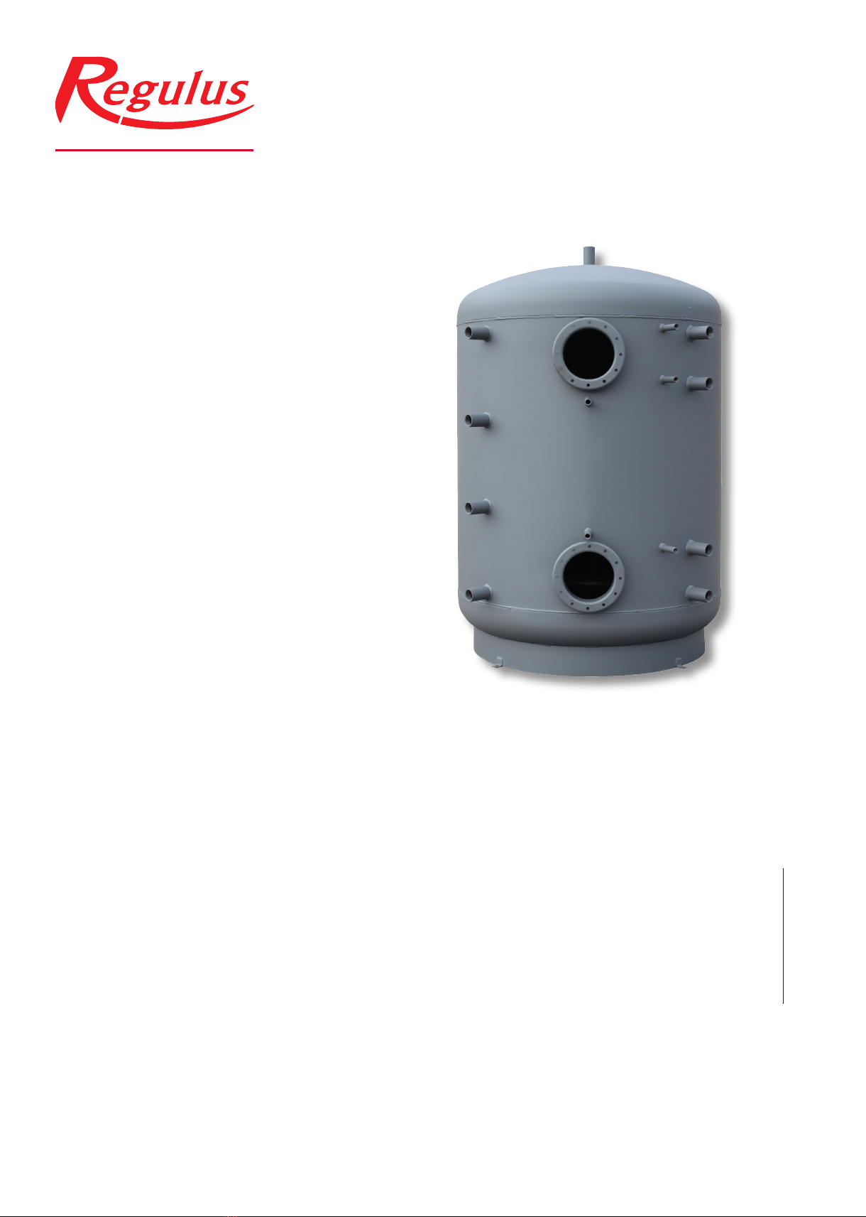
PSWF Thermal Stores are intended for storing and subsequent distribution of thermal energy from solid-fuel red boil-
ers, heat pumps, solar collectors, electric boilers etc. This thermal store shall be always connected to a sealed heat-
ing circuit. It is tted with two anges ready to receive suitably sized tube heat exchangers. Mating anges for heat
exchangers with either G 1” or G ¾” connections are available as an option. When no heat exchanger is installed, a
blind ange shall be used (option).
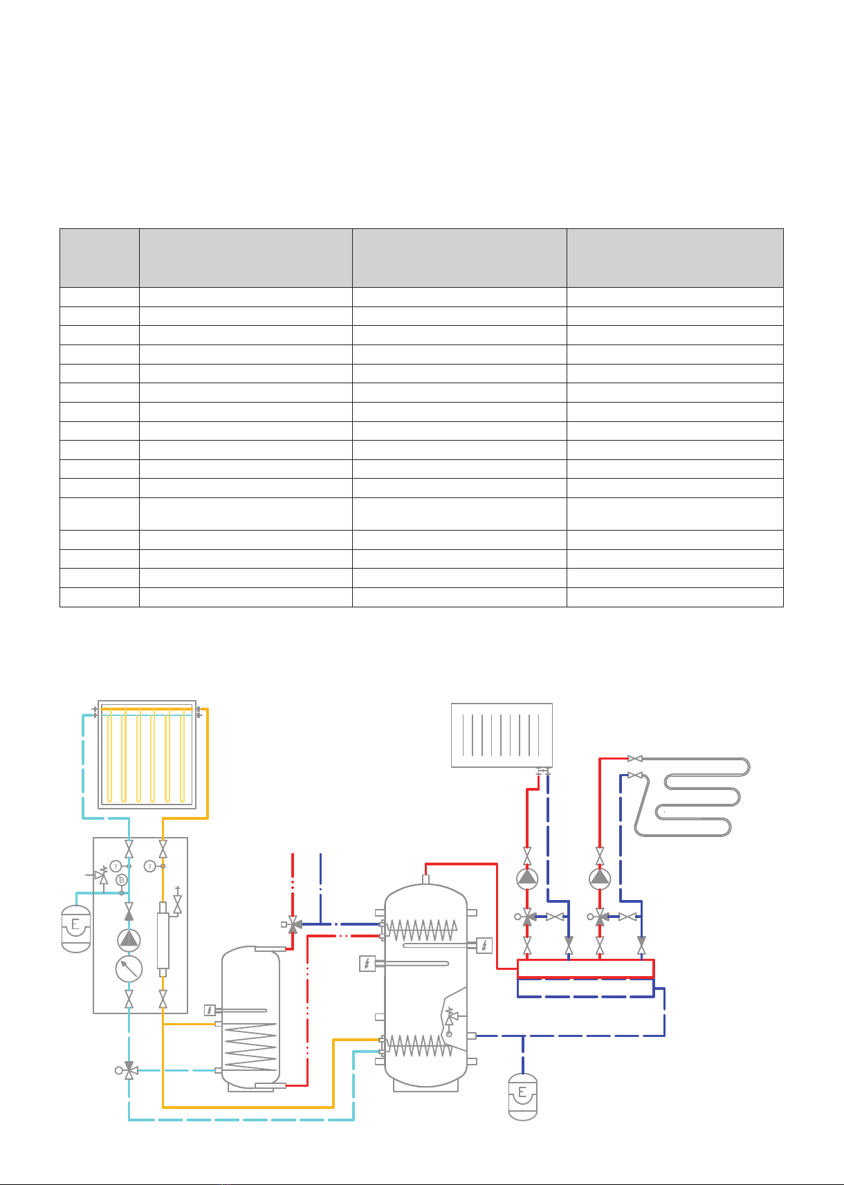
These heat exchangers are made of nned copper tubes that feature larger surface area and better heat transfer.
The lower heat exchanger usually connects to a solar system and the upper one is used for DHW heating (continu-
ous) which limits signicantly the risk of Legionella bacteria formation. The tanks are also tted with nine G 2,5“ side
sleeves to connect heat sources, four G ½“ ones for sensor sheaths and one G ½“ sleeve for a safety valve. El. heat-
ing elements can be installed into the 2,5” sleeves using a reducing piece.
1.1 - Models
Three models of 3027, 3996 and 4994 l capacity.
1.2 - Tank protection
The inner surface has no nish, no anticorrosion protection, the outer surface is lacquered in gray.
1.3 - Thermal insulation
Tank insulation is available as a separate item, installed on the tank on the spot for easier handling. The insulation is
made of 100 mm thick eece and tted with a zippered outer layer in PU leather.
1.4 - Connection points on the tank
2 anges with 210 mm inner diam.
8 side sleeves in a 90° sector, G 2,5” F thread
1 top sleeve, G 2,5” F thread
4 side sleeves for sensor sheaths, G ½” F thread
1 side sleeve for a 3 bar safety valve (included), G ½” F thread
1.5 - Packing
Tanks are delivered standing, each screwed to its pallet, packed in bubble wrap.
Included in the package are gaskets and bolts for the flange.
2 - General Information
This Owners Manual is an integral and important part of the product and must be handed over to the User. Read care-
fully the instructions in this Manual as they contain important information concerning safety, installation, operation and
maintenance. Keep this Manual for later reference. The appliance shall be installed by a qualied person according to
valid rules and Manufacturer‘s Instructions.
This appliance is designed to accumulate heating water and distribute it subsequently. It shall be connected to a
heating system and heat sources. The equipment is suitable also for continuous water heating. In such a case, the
customer needs to buy a suitably sized heat exchanger (available as accessory) and have it installed into the upper
ange.
Using the thermal store for other purposes than above described (e.g. as a DHW tank) is forbidden and the
manufacturer accepts no responsibility for damage caused by improper or wrong use.
The thermal store shall not be used as a DHW tank!

│4
3 - Technical Data and Dimensions
Type - model PS2F 3000 N25 PS2F 4000 N25 PS2F 5000 N25
Tank code a14460 14463 14466
Insulation code b16363 16364 16365
Total uid volume in tank [l] c3027 3996 4994
Empty weight [kg] d315 429 491
Tipping height without insulation [mm] V1 2189 2490 2970
Dimensions [mm] øD1 1700 1800 1800
øD 1500 1600 1600
B1 1545 1815 2315
B2 445 465 465
H1 2065 2355 2855
H2 445 465 465
C1 1570 1840 2340
C2 715 780 925
C3 1265 1490 1855
T1370 1630 2030
P670 700 800
U1 1545 1815 2315
U2 645 675 775
U3 1185 1375 1705
U4 805 905 1075
U5 1345 1605 2005
L1 1465 1735 2235
L2 535 555 555
Tank code: ....................................................................................... a
Insulation code: ............................................................................... b
Total uid volume in tank: ................................................................ c
Max. working temperature in tank: .................................................. 95 °C
Max. working pressure in tank PS2F 3000 N25 ÷ PS2F 5000 N25: 3 bar
Empty weight: ................................................................................. d
Tipping height without insulation: .................................................... V1
Dimensions
TAPPINGS
pos. connection
Heat sources
B1 G 2,5" F
B2 G 2,5" F
Heating system
H1 G 2,5" F
H2 G 2,5" F
Control and safety
C1 G1/2" F
C2 G 1/2" F
C3 G 1/2" F
TG 1/2" F
PG 1/2" F
Universal inlet / outlet
U1 G 2,5" F
U2 G 2,5" F
U3 G 2,5" F
U4 G 2,5" F
U5 G 2,5" F
Flanges
L1 12 x M12
L2 12 x M12
ØD1
ØD
H1

5 │
HW CW
4 - Operation
This thermal store is designed to store heat and heat water for space heating in domestic or industrial applications,
however always in sealed pressure circuits with forced circulation. In the thermal store, heating water is heated up
from several heat sources like various types of hot-water boilers, renewable energy sources (heat pumps, solar collec-
tors), or electric heating elements.
The thermal store shall be connected to a heat source through G 2,5” threaded ttings. Should it be connected to a
solar system, too, this shall be done through a suitably sized heat exchanger installed into the lower ange.
5 - Examples of ports allocation
Conn. point
Example I.
Solar collectors
+ el. heating elements
Example II.
Solar collectors
+ gas boiler
Example III.
Solar collectors + solid fuel boiler +
el. heating elements
H1 outlet to heating system outlet to heating system outlet to heating system
B1 plug inlet to boiler (gas-red) inlet from boiler (solid-fuel-red)
U3 el. heating element plug el. heating element
U4 plug plug plug
B2 plug plug outlet to boiler (solid-fuel-red)
H2 drain valve drain valve drain valve
U2 inlet from heating system inlet from heating system inlet from heating system
U5 el. heating element plug el. heating element
U1 plug inlet from heating system plug
Ptemperature sensor for solar system temperature sensor for solar system temperature sensor for solar system
Tthermometer thermometer thermometer
C3 thermostats for heating elements
(adjustable+limit)
temperature sensor to heating controller thermostats for heating elements
(adjustable+limit)
C1 sensor for controller with OTC sensor for controller with OTC sensor for controller with OTC
C2 safety valve, G 1/2“, 3 bar safety valve, G 1/2“, 3 bar safety valve, G 1/2“, 3 bar
L1 heat exchanger for preheating DHW tank heat exchanger for preheating DHW tank heat exchanger for preheating DHW tank
L2 solar heat exchanger solar heat exchanger solar heat exchanger
Connections depend on the circuit to be connected, the a.m. examples are informative only.
Example I.
Solar collectors and el. heating elements.

│6
Example II.
Solar collectors and combi gas boiler.
Example III.
Solar collectors, solid fuel boiler and el. heating elements.
HW
CW
gas boiler
with DHW tank
HW
CW

7 │
6 - Installation and Commissioning
Installation shall meet valid rules and may be done by qualied staff only.
Defects caused by improper installation, use or handling are not covered by warranty.
After the tank is installed and connected to an existing heating system, it is recommended to clean the entire heating
system using a suitable cleaning agent, e.g. MR-501/R.
Anti-corrosion protective liquid should be also used, e.g. MR-501/F or F1.
6.1 - Connection to heat sources
Place the tank on the oor, as close to your heat source as possible. Mount the insulation, cf. Installing Insulation on
the Tank. Connect the heating circuits to inlets and outlets respecting the thermal stratication in the tank. Install a
drain valve at the lowest point of the tank. Install an air vent valve at the highest point of the system. Insulate all the
connecting piping.
6.2 - Connection to a solar system
This tank is suitable for use with a solar system. In such a case a suitably sized heat exchanger shall be installed into
the lower ange. Insulate meticulously all the piping between the tank and the solar system.
6.3 - El. heating element installation
The tank may be tted with electric heating elements up to 12kW output. They can be power-supplied either directly
(elements with built-in thermostat) or via a controller for the entire heating system.
All electric heating elements shall be protected by a safety thermostat.
Electric heating elements shall be installed by an authorized person only.
6.4 - Commissioning
The tank shall be lled up together with the heating system, respecting valid standards and rules. In order to minimize
corrosion, special additives for heating systems should be used. The quality of heating water depends on the quality of
lling water at commissioning, on the top-up water and on the frequency of topping up. This has a strong inuence on the
lifetime of heating systems. Poor quality of heating water may cause problems like corrosion or incrustation, esp. on heat
transfer surfaces.
Fill the heating circuits with the appropriate uids and air-bleed the entire system. Check all connections for leaks and
verify the system pressure. Set the heating controller in compliance with the documentation and manufacturer’s recom-
mendations. Check regularly proper function of all control and adjustment elements.

│8
7 - Installing Insulation on the Tank
Instructions
Product description
Fleece thermal insulation with PU leather surface.
Warning
Insulation installation shall be done in two or three persons, depending on its size. The insulation must not be
installed at temperatures below 20 °C. If this cannot be avoided, the insulation shall be pre-warmed in another room
to at least 20 °C. It is impossible to install insulation of lower temperature, there is a risk of damage, esp. to the zipper.
Do not use any tools for installation.
Keep away from open re.
Installing Insulation
1. Fix the tank following installation instructions.
2. Wrap the insulation around the tank carefully. Check that the insulation adheres to its body perfectly. This can be
reached by rubbing and patting the insulation by hand from its center evenly in both directions until the insulation
adheres to the tank’s surface completely and no bubbles are left.
3. Use the holes for sleeves as a rest during the insulation installation.
4. At least one person presses the insulation to the tank, pulling both ends together. The other person closes the
zippe.
5. Put on the upper insulation and cover.
6. Push on the covering plastic rosettes depending on the size of sleeves, or put on the ange plug(s) with insulation.
7. Finish the tank installation in compliance with the respective instructions and valid standards and rules.
Warranty on insulation
The insulation is covered by a 24-month warranty. This period starts the next day after the insulation is sold.
□ Warranty shall become null and void if:
○ the procedure described in the Installation Manual was not respected,
○ the product was used for other purposes than intended.
□ Warranty does not cover:
○ usual wear and tear,
○ damage caused by re, water, electricity or a natural disaster,
○ defects caused by failure to use the product in compliance with its intended purpose, by improper use and
insufcient maintenance,
○ defects caused by mechanical damage to the product,
○ defects caused by tampering or incompetent repair.

9 │
Návod na instalaci měkké izolace s koženkovým povrchem
Installation instructions for soft insulation with PU leather surface
1
2
/
2015
REGULUS spol. s r.o.
Do Koutů 1897/3 http://www.regulus.cz | http://www.regulus.eu
143 00 Praha 4 E-mail: obchod@regulus.cz | E-mail: sales@regulus.eu
ČESKÁ REPUBLIKA | CZECH REPUBLIC

│10
8 - Maintenance
If the tank is tted with a heating element, disconnect it from the mains rst. Clean the exterior of the tank with a soft
cloth and a mild detergent. Never use abrasive cleaners or solvents.
Check all connections for leaks.
9 - Disposal
Packing shall be disposed of in compliance with the valid rules. When the product reaches the end of its life, it shall
not be disposed of as household waste. It shall be dropped off at a Local Waste Recycling Center. Insulation shall be
recycled as plastic and the steel vessel as scrap iron.
10 - Warranty
This product is covered by warranty under the conditions listed in this Manual and in compliance with the Warranty
Certicate. A Warranty Certicate is an integral part of this thermal store scope of supply.

11 │

©2019 We reserve the right to errors, changes and improvements without prior notice.
REGULUS spol. s r.o.
E-mail: sales@regulus.eu
Web: www.regulus.eu
v1.2-07/2019
This manual suits for next models
2
Table of contents
Other Regulus Tank Equipment manuals