manuals.online logo
Brands
  1. Home
  2. •
  3. Brands
  4. •
  5. REMEHA
  6. •
  7. Boiler Supplies
  8. •
  9. REMEHA Rematic 2945 C3K+ User manual

REMEHA Rematic 2945 C3K+ User manual

Montage instructie
Assembly instructions
Instructions de montage
Montageanweisung
rematic 2945 C3K +
Remeha Gas 310 ECO
2
4x
2x
2x
a
b
OFF
230 V
+
Inhoud verpakking
Set contents
Contenu du jeu
Inhalt des Bausatzes
3
2
21
4x
1
1
K1
K2
4
4x
3
X29
1
or
vt
bl
rd
wt
rs
gs
zw
bl
br
rd br
wt
wt
rd
bl
br
wt
rd
br
bl
zw
rd
rd
gn
wt
wt
br
br
19
18
2
X30
P12 P11
bl br gs zwwt rd vt or rs
P2 P3
654321 54321 wt
rd wt wt
rd br
br
rd
gn zw
12
K2
bl br
K1 Ngrün
L
N
N
L
grün
N
zu
N
Lrot
auf
rot
zu
auf
N
FS3611
FS
rot
Bi
Bi
gr¸n
FS3611
FS
Appl.
grün
_
Bv
_
rot
+
_
+
_
Bus
Bk
Ba
Bb
5
4
P3
P2
P11
P12
6
X16
9
2x
8
2x
7
X16A
X16
10
5
14
K1
11
b
a
15
K1
K1
12
K2/X24
K2A/X24A
13
6
Ba Bb
L N L N
U 2U 1
auf
M 2
N
M 1
zu zuauf N
PE
PE
auf
zu
N
N
auf
zu
N
N
PE
PE
L
L
Bi
FS
FS3611
rot
FS
FS3611
Bi
gr n
L
N
+
+
_
__
_
Appl.
Bus
Bv 1 Bv 2
L N
BLP
PE
N
Bk
Aansluitschema rematic 2945 C3K in een installatie met n Gas 310 ECO
Wiring diagram rematic 2945 C3K for Gas 310 ECO in a single boiler installation
Sch ma de raccordement rematic 2945 C3K pour une chaudi re Gas 310 ECO dans une installation avec une chaudi re
Elektroschema rematic 2945 C3K f r Gas 310 ECO in eine Einkesselanlage
Ba Buitenvoeler Outdoor sensor Sonde ext rieure Aussenf hler
Bb Boilervoeler DHW sensor Sonde ballon Brauchwasserf hler
Bv1 gr n Aanvoervoeler menggroep 1 Sensor mixing group 1 Sonde d part groupe 1 Vorlauff hler Kreis 1
Bv2 rot Aanvoervoeler menggroep 2 Sensor mixing group 2 Sonde d part groupe 2 Vorlauff hler Kreis 2
M1 gr n Mengklep menggroep 1 Mixing valve group 1 Vanne m langeuse groupe 1 Mischer Kreis 1
M2 rot Mengklep menggroep 2 Mixing valve group 2 Vanne m langeuse groupe 2 Mischer Kreis 2
U1 gr n Pomp menggroep 1 System pump mixing group 1 Circulateur groupe 1 Pumpe Kreis 1
U2 rot Pomp menggroep 2 System pump mixing group 2 Circulateur groupe 2 Pumpe Kreis 2
HK1 gr n CV groep 1 Heating group 1 Groupe chauffage 1 Heizkreis 1
HK2 rot CV groep 2 Heating group 2 Groupe chauffage 2 Heizkreis 2
BLP Boilerpomp DHW pump Pompe de charge ballon Boilerladepumpe
TV Thermostaat kraan Thermostatic valve Vanne thermostatique Thermostatventil
b
a
Bi
gr n
FS3611
FS
gr n
_
Bv
_
rot
+
_
+
_
Bk
Ba
Bb
0N
65
FB 5240
HK2 rot
FB 5240
56
0N
HK1 gr n
b
a
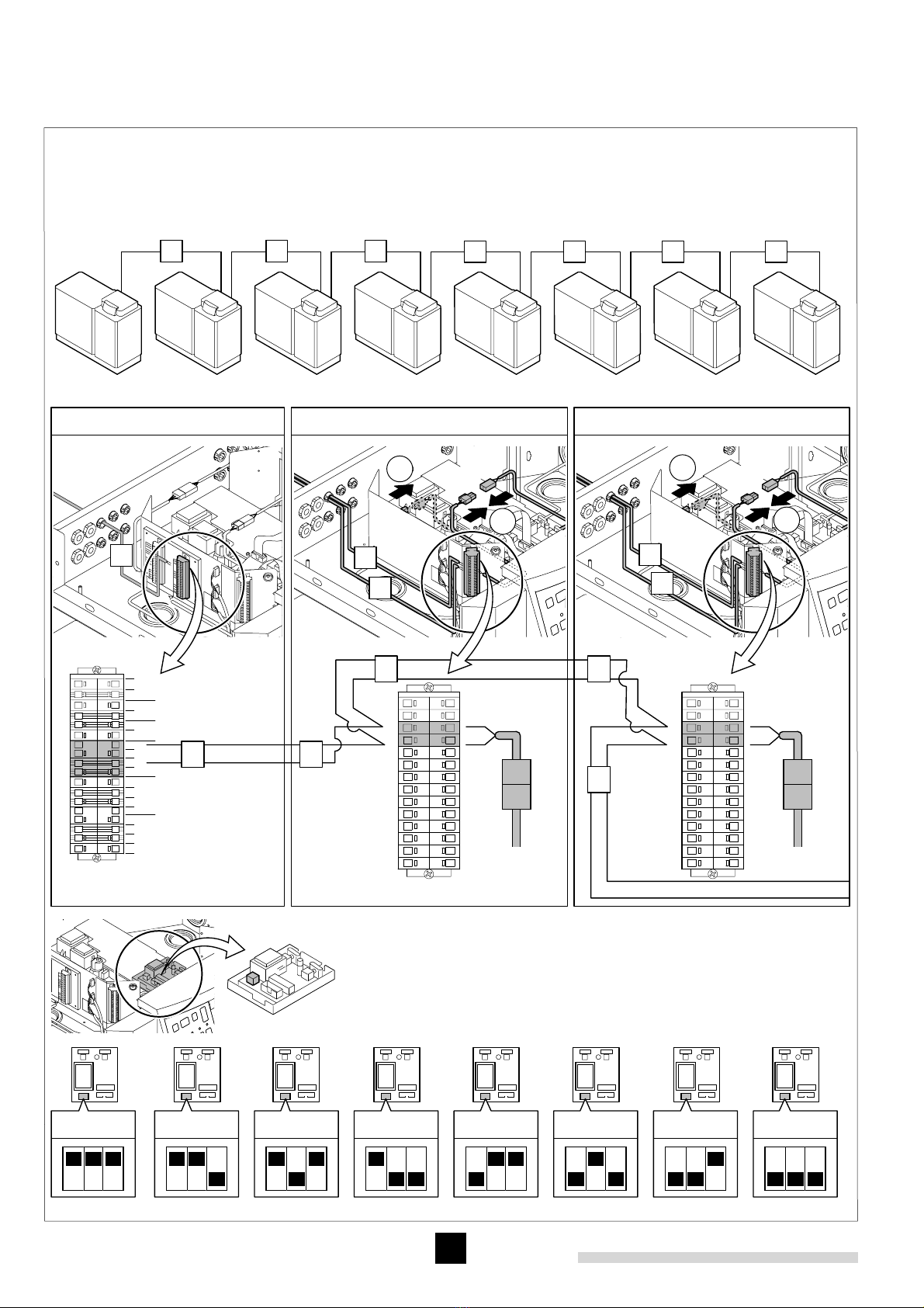
Aansluitschema rematic FB 5240 digitale afstandsbediening (installatie met n regelaar)
Wiring diagram rematic FB 5240 digital remote control (for an installation with a single controller)
Sch ma de raccordement rematic FB 5240 t l commande digitale (pour une installation avec un r gulateur)
Elektro-Anschlussplan rematic FB 5240 digitalem Fernbedienung (f r eine Installation mit einem Regler)
Appl.Bus Digitale bus Digital bus Communication digitale Digitaler Bus
FB 5240 Digitale afstandsbediening Digital remote control T l commande digitale Digitale Fernbedienung
aBuitenvoeler Outdoor sensor Sonde ext rieure Aussenf hler
bGemeenschappelijke aanvoervoeler System flow sensor Sonde d part commune Gemeinsamer Vorlauff hler
16
7
M1
U1
Bv1
TVHK1 TV HK2
Bv2
U2
Bb
BLP
M2
As
Rs
Ba
2945 C3K
MCBA
8
Ba Buitenvoeler Outdoor sensor Sonde extérieure Aussenfühler
Bb Boilervoeler DHW sensor Sonde ballon Brauchwasserfühler
Bk Gemeenschappelijke aanvoervoeler System flow sensor Sonde départ commune Gemeinsamer Vorlauffühler
Bv1 grün Aanvoervoeler menggroep 1 Sensor mixing group 1 Sonde départ groupe 1 Vorlauffühler Kreis 1
Bv2 rot Aanvoervoeler menggroep 2 Sensor mixing group 2 Sonde départ groupe 2 Vorlaujfühler Kreis 2
M1 grün Mengklep menggroep 1 Mixing valve group 1 Vanne mélangeuse groupe 1 Mischer Kreis 1
M2 rot Mengklep menggroep 2 Mixing valve group 2 Vanne mélangeuse groupe 2 Mischer Kreis 2
U1 grün Pomp menggroep 1 System pump mixing group 1 Circulateur groupe 1 Pumpe Kreis 1
U2 rot Pomp menggroep 2 System pump mixing group 2 Circulateur groupe 2 Pumpe Kreis 2
HK1 grün CV groep 1 Heating group 1 Groupe chauffage 1 Heizkreis 1
HK2 rot CV groep 2 Heating group 2 Groupe chauffage 2 Heizkreis 2
BLP Boilerpomp DHW pump Pompe de charge ballon Boilerladepumpe
TV thermostaat kraan Thermostatic valve Vanne thermostatique Thermostatventil
Uw1 Ketelpomp 1 Boiler pump 1 Circulateur chaudière 1 Kesselpumpe 1
Uw2 Ketelpomp 2 Boiler pump 2 Circulateur chaudière 2 Kesselpumpe 2
Aansluitschema rematic 2945 C3 K met Gas 310 ECO in cascade
Wiring diagram rematic 2945 C3 K for Gas 310 ECO in a multiple boiler installation
Schéma de raccordement rematic 2945 C3 K pour Gas 310 ECO en cascade
Elektro-Anschlussplan rematic 2945 C3 K für Gas 310 ECO in einer Mehrkesselanlage
Ba Bb
L N L N
U2U1
auf
M2
N
M1
zu zuauf N
PE
PE
auf
zu
N
N
auf
zu
N
N
PE
PE
L
L
Bi
FS
FS3611
rot
FS
FS3611
Bi
gr¸n
L
N
+
+
_
__
_
Appl.
Bus
Bv 1 Bv 2
L N
BLP
Bk
PE
N
9
M1
U1
Uw1 Uw2
UV UV
Bv1
Bk
TVHK1 TV HK2
Bv2
U2
Bb
BLP
M2
As
Rs
Ba
2945 C3K
MCBA
As
Rs
10
Bi
grün
FS3611
FS
Appl. Bus
grün
Bv
rot
+
+
--
+
-
+
-
+
-
+
-
Bk
Ba
Bb
-
+
-
+
-
+
-
+
X24
X24a
X24
X24a
x x
y y
y
X24a
X24
1
2
X24a
X24
y
x
1
2
x
y
y
No.1 No.2 No.3-4-5-6-7-8
No. 1 No. 2 No. 3 No. 4 No. 5 No. 6 No. 7 No. 8
Bekabeling tussen de cascadeketels
Wiring between boilers of a multiple boiler installation
Câblage entre les chaudières en cascade
Verkabelung zwischen Kessel einer Mehrkesselanlage
No. 1 No. 2 No. 3 No. 4 No. 5 No. 6 No. 7 No. 8
x y y y y y y
Instelling dipswitches op interface per ketel uit een cascade
Position dipswitches on the interface of each boiler in a multiple boiler installation
Position interrupteurs sur l’interface de chaque chaudière d’une cascade
Position der Schalter der Schnittstelle pro Kessel einer Mehrkesselanlage
11
ON
230 V
+
12
4x
2
17
© Copyright
All technical and technological information contained in these technical instructions,
as well as any drawings and technical descriptions supplied, remain our
property and shall not be multiplied without our prior consent in writing.
Ours is a policy of continuous development. We reserve the right to alter
specifications without prior notification.
Subject to alterations.
58838 - 1204

Other REMEHA Boiler Supplies manuals

REMEHA Celcia MC4 User manual

REMEHA

REMEHA Celcia MC4 User manual

REMEHA MCBA User manual

REMEHA

REMEHA MCBA User manual

REMEHA rematic 2945 C3 K User manual

REMEHA

REMEHA rematic 2945 C3 K User manual

REMEHA Rematic 142 User manual

REMEHA

REMEHA Rematic 142 User manual

Popular Boiler Supplies manuals by other brands

Webstone Hydro-Core user guide

Webstone

Webstone Hydro-Core user guide

Miura BP-201 Quick start up guide

Miura

Miura BP-201 Quick start up guide

Miura WP2-200A installation manual

Miura

Miura WP2-200A installation manual

Beretta B23 manual

Beretta

Beretta B23 manual

Ecotermal 6 MRT Assembly and operation manual

Ecotermal

Ecotermal 6 MRT Assembly and operation manual

Xylem McDonnell & Miller 67 Series instruction manual

Xylem

Xylem McDonnell & Miller 67 Series instruction manual

oventrop Regumat-180 plus Installation and operating instructions for the specialised installer

oventrop

oventrop Regumat-180 plus Installation and operating instructions for the specialised installer

NTI FTV110C instructions

NTI

NTI FTV110C instructions

Immergas 3.032264 Instruction and warning book

Immergas

Immergas 3.032264 Instruction and warning book

LK 816 ThermoKit E Eco instruction manual

LK

LK 816 ThermoKit E Eco instruction manual

manuals.online logo
manuals.online logoBrands
  • About & Mission
  • Contact us
  • Privacy Policy
  • Terms and Conditions

Copyright 2025 Manuals.Online. All Rights Reserved.