Toro 07161 User manual

FormNo.3420-758RevA
BallCageKit
Workman®GTXUtilityVehicle
ModelNo.07161—SerialNo.400000000andUp
InstallationInstructions
WARNING
CALIFORNIA
Proposition65Warning
ThisproductcontainsachemicalorchemicalsknowntotheStateofCalifornia
tocausecancer,birthdefects,orreproductiveharm.
Note:Determinetheleftandrightsidesofthemachinefromthenormaloperatingposition.
LooseParts
Usethechartbelowtoverifythatallpartshavebeenshipped.
ProcedureDescriptionQty.Use
1Nopartsrequired–Preparethemachineforinstallation.
2Nopartsrequired–Removetheseatassembly,handholds,
sidepanels,andrubbercovers.
Floorbrace2
Flange-headbolts(5/16x1inch)20
3Flangelocknut(5/16inch)20
Installtheoorbraces.
LeftROPSbracket1
RightROPSbracket1
Flange-headbolt(1/2x3inches)6
Flatwasher(1/2inch)10
Locknut(1/2inch)6
Rollbar1
Flange-headbolt(1/2x3-1/2inches)4
Locknut(1/2inch)4
Cabletie2
4
Plasticrivet4
InstalltheROPSassembly.
Seatbelt2
Seatlatch2
Hex-headbolt(7/16x1inch)4
Flatwasher(7/16inch)8
5
Locknut(7/16inch)4
Installthesidepanels,handholds,and
seatbelts.
©2017—TheToro®Company
8111LyndaleAvenueSouth
Bloomington,MN55420
Registeratwww.Toro.com.OriginalInstructions(EN)
PrintedintheUSA
AllRightsReserved*3420-758*A

ProcedureDescriptionQty.Use
Leftwindshieldsupport1
Rightwindshieldsupport1
Frontsupport1
Rearcanopysupport1
Left,frontmountbracket1
Right,frontmountbracket1
Left,rearmountbracket1
Right,rearmountbracket1
Left,rearcornergusset1
Right,rearcornergusset1
Left,frontcornergusset1
Right,frontcornergusset1
Frontcrosslink1
Crosslinktube2
Flangenut(5/16inch)30
Nut(1/4inch)2
Hex-headangebolt(1/4x1-1/2inches)2
Carriagebolt(5/16x1-3/4inches)16
Hex-angebolt(5/16x1inch)2
Carriagebolt(5/16x2-3/4inches)6
6
Carriagebolt(5/16x1inch)4
InstalltheROPSextension.
7Nopartsrequired–Installtheseatassembly.
Rightdoorassembly1
Leftdoorassembly1
Doortether2
Rightdoorhinge2
Leftdoorhinge2
Carriagebolt(5/16x2-3/4inches)4
Shoulderbolt(5/16x1/2inch)4
Spacer4
8
Flangenut(5/16inch)8
Installthedoors.
9Nopartsrequired–Removethehoodandbumper.
Headlightguard2
10Flangebolt(5/16x5/8inch)4Installtheheadlightguards.
Ball-pickermount1
Bottombracket1
Flangebolt(3/8x1inch)14
11Flangelocknut(3/8inch)14
Installtheball-pickermount.
12Nopartsrequired–Installthebumperandhood.
Windshield1
Shoulderbolt(5/16x1-1/4inches)8
Hex-headangebolt(1/4x1-1/2inches)5
Rubberbushing16
Backupwasher8
Windshieldsupportassembly1
Windshieldbracket1
Nut(5/16inch)8
13
Nut(1/4inch)5
Installthewindshield.
2
ProcedureDescriptionQty.Use
Latchpin2
Thrustwasher4
Pinguard2
14Jamnut2
Assemblethelatchpin.
Sunshade1
Clip2
Sealingwasher4
Hex-angebolt(1/4x1inch)4
Frictionwasher2
Plasticwasher4
15
Flangebushing2
Installthecanopy.
16Nopartsrequired–Completetheinstallation.
1
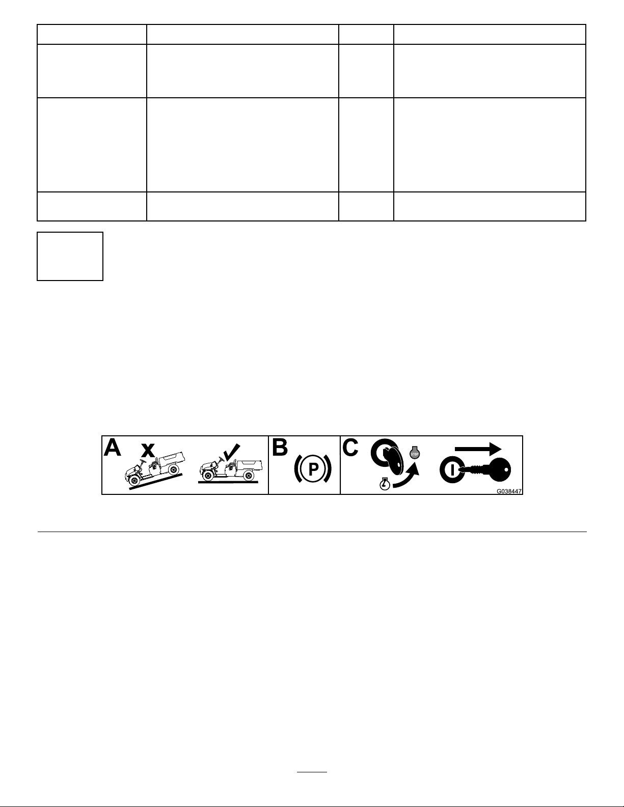
PreparingtheMachine
NoPartsRequired
Procedure
1.Parkthemachineonalevelsurface.
2.Engagetheparkingbrake.
3.Shutofftheengineandremovethekey.
g038447
Figure1
3
2
RemovingtheSeat
Assembly,Handholds,
SidePanels,andRubber
Covers
NoPartsRequired
RemovingtheSeatAssembly
1.Pushtheseatassemblyforwardtotheraised
position.
2.Slidetheseatassemblytothesideoutofthe
pins,andlifttheseatassemblyupward(Figure
2).
g190187
Figure2
1.Pins
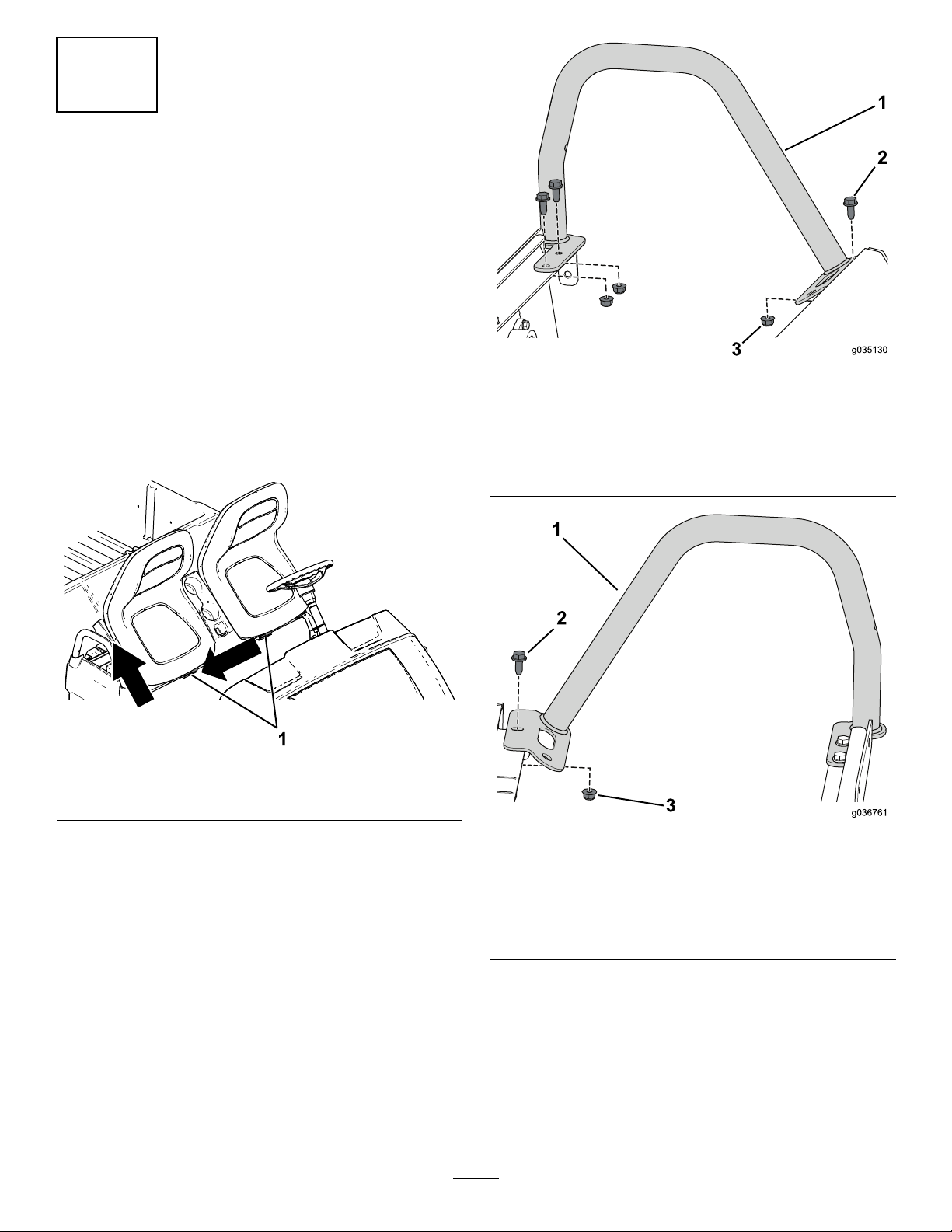
RemovingtheHandholds
Removethe3angebolts(5/16x3/4inch)and3
angenuts(5/16inch)securingtherightandleft
handholds;removethehandholds(Figure3and
Figure4).
g036760
Figure3
LeftHandholdShown
1.Lefthandhold3.Flangenut(5/16inch)
2.Flangebolt(5/16x3/4
inch)
g036761
Figure4
RightHandholdShown
1.Righthandhold3.Flangenut(5/16inch)
2.Flangebolt(5/16x3/4
inch)
4

RemovingtheSidePanels
ForElectricMachines
1.Disconnectthebatteries;refertoyourmachine
Operator’sManual.
Note:Correctlyfollowtheprocedurefor
disconnectingthebatteries.Disconnectthe
mainnegative-batterycable(black),then
disconnectthemainpositive-batterycable(red).
2.Removethechargerandthechargercablefrom
thechargerbracket(Figure5).
g191363
Figure5
LeftSideShown
1.Charger2.Chargerbracket
3.Removethe4torx-headscrews(M6.0x22mm)
securingthechargerbrackettotheleftside
panel(Figure6).
g193101
Figure6
LeftSideShown(T opView)
1.Leftsidepanel3.Torx-headscrew(M6.0x
22mm)
2.Chargerbracket
5
Table of contents
Other Toro Automobile Accessories manuals


Popular Automobile Accessories manuals by other brands


ULTIMATE SPEED
ULTIMATE SPEED 279746 Assembly and Safety Advice

SSV Works
SSV Works DF-F65 manual

ULTIMATE SPEED
ULTIMATE SPEED CARBON Assembly and Safety Advice

Witter
Witter F174 Fitting instructions

WeatherTech
WeatherTech No-Drill installation instructions

TAUBENREUTHER
TAUBENREUTHER 1-336050 Installation instruction