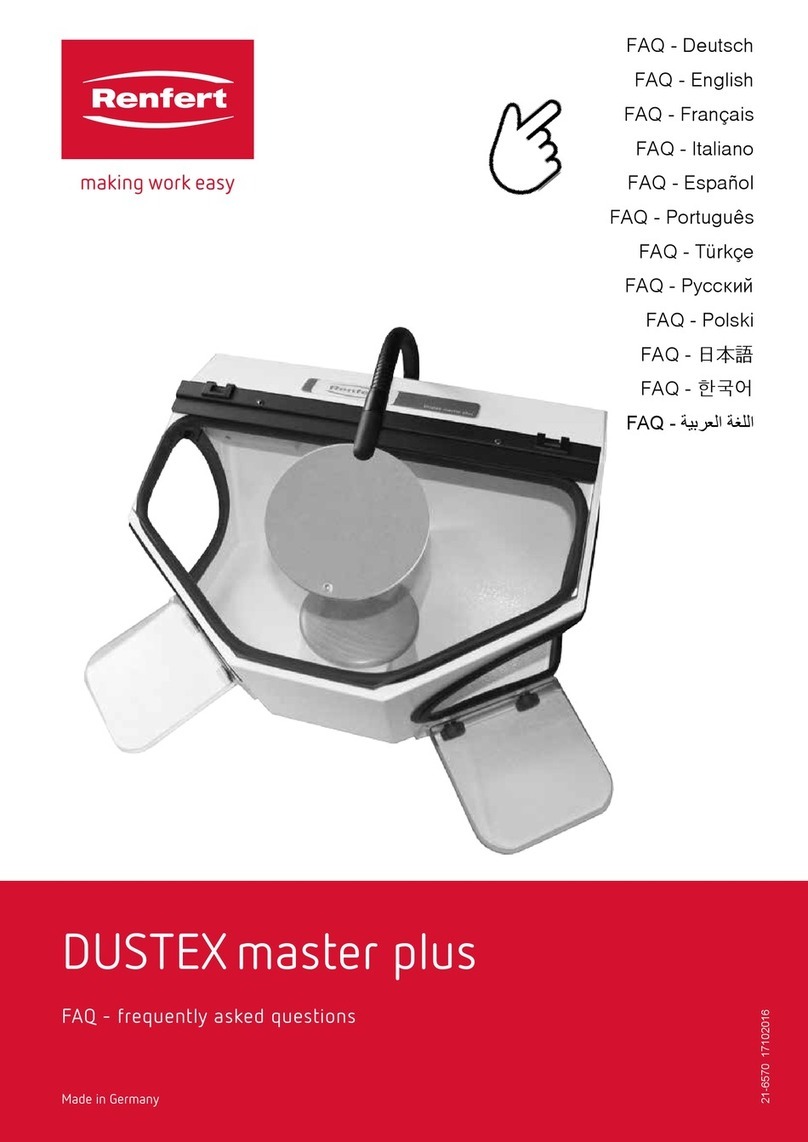
Renfert Dustex master plus User manual

#FEJFOVOHTBOMFJUVOH
*OTUSVDUJPONBOVBM߭.PEFEtFNQMPJ
*TUSV[JPOJEߤVTP߭*OTUSVDDJPOFTQBSBFMTFSWJDJP
ᜪ◅一⥢⩌߭瞦綣砞煿砖
Made in Germany
Dustex master plus
No. 2626-xxxx
0210 21-6570 A
Ideen für die Dentaltechnik

4FSJFOOVNNFS)FSTUFMMEBUVNVOE(FS¤UF7FSTJPOCFGJOEFOTJDIBVGEFN(FS¤UF5ZQFOTDIJME
4FSJBMOVNCFSBOEEBUFPGNBOVGBDUVSJOHBSFTIPXOPOUIFUZQFQMBUFPGUIFVOJU
-FOVN©SPEFT©SJFFUMBEBUFEFGBCSJDBUJPOTFUSPVWFOUTVSMBQMBRVFTJHOBM©UJRVFEFM࣌BQQBSFJM
*MOVNFSPEJTFSJFFMBEBUBDPTUSV[JPOFTJUSPWBOPTVMMBUBSHIFUUBEFMM࣌BQQBSFDDIJP
&MOºNFSPEFTFSJFZMBGFDIBEFGBCSJDBDJ³OFTU¡OJOEJDBEPTFOMBQMBDBJEFOUJGJDBEPSBEFMBQBSBUP
ᄴᅧᄟᅨ历㈓Ⴅ朙渼䐁აᄎჹ曡嶊ჴᅍᅵᄵᅤᅰჵ曡嶊ჴ㖧历㈓ᅦᅖᅨჱ栴津მᄒწᄄჟႦ
饝逭鰽螙錅麝黱鷽鸑銐蒱蒱錅麅鷁蒱蒱鷙鄆ꦑ鱑ꫝ饝誙鰵鸉餶襉襥

1 2
43
5 6
7 8

9 10
11 12
13 14
15 16

- 9 - EN
Dustex master plus
Nr. 2626-xxxx
ENGLISH
1. Introduction
We are pleased with your decision to purchase a
Renfert Dustex master plus dust extractor box.
The Dustex master plus is an extraction box fitted
with an extraction duct and arm supports for a more
comfortable working position.
Please read the following operating in-
structions carefully and observe all the
information they contain in order to ensu-
re long and trouble-free service.
2. Application Area
In dental technology and clinical laboratories as well
as similar professional fields (e.g., goldsmiths, model
builders), grinding acrylics, plasters, porcelains, and
other materials generates dusts and vapours. The ex-
traction box reduces the effects of dusts and vapours,
thus providing improved protection for the operator.
The large openings on the sides offer great freedom
of movement, but it is precisely for this reason that
the extraction box is not suitable for use with blasting
units.
2.1 Ambient Conditions
(in accordance with DIN EN 61010-1)
The unit may only be operated:
• Indoors;
• Up to an altitude of 2,000 m [6,500 ft] above sea
level;
• At an ambient temperature range of 5 - 40ºC
[41 - 104ºF] *);
• At a maximum relative humidity of 80% at 31ºC
[87.8ºF], dropping linearly to 50% relative humidity
at 40ºC [104ºF];
• With a mains power supply whose voltage fluctua-
tions do not exceed 10% of the rated value;
• Under over-voltage category II conditions.
• Under contamination level 2 conditions;
*) Between 5 - 30ºC [41 - 86ºF] the unit can be operated at a
relative humidity of up to 80%. At temperatures between 31 -
40ºC [87.8 - 104ºF] the humidity must decrease proportionally
in order to ensure proper operability (e.g., at 35ºC [95ºF] = 65%
relative humidity, at 40ºC [104ºF] = 50% relative humidity). The
unit may not be operated at temperatures above 40ºC [104ºF].
3. Hazard Information
3.1 Employed Symbols
The following symbols are used in these instructions
and on the unit:
Danger
This indicates an imminent risk of injury.
Electrical hazard
There is a risk of electrical shock.
Attention
Failure to observe the associated informa-
tion can result in damage to the unit.
Note
The operating instructions contain useful
information to make handling easier.
Wear eye protection.
Only for indoor use.
Before opening the unit, always discon-
nect it from the power supply.
Note the operating instructions.
3.2 Hazard Information
• The dust extractor cabinet is an electric unit
and, as such, carries with it a certain inherent
potential electrical hazard.
• The unit may not be operated until it has been
modified to comply with the local electrical
connection requirements. The necessary
alterations may only be performed by a
qualified electrician.
• The unit may only be operated if the
information on the nameplate conforms with
the specifications of your local mains power
supply.
• Never operate the dust extractor cabinet
without an appropriate extraction system
or suitable personal protective clothing, as
operating the unit without proper extraction
will not provide adequate protection against
dusts and vapours which may be hazardous to
your health. The type of extraction employed
must be appropriate to the dusts and vapours
generated during processing. In this regard,
please note the requirements of EN 60335-2-
69, Attachment AA, or ask your professional
organization or regional authority.

- 10 -
EN
• The extraction box is not suitable for use in
conjunction with blasting units.
• Improper use of grinding tools in the extraction
box carries with it the potential risk of eye and
skin injuries.
• Never grind in the direction of your eyes or
uncovered areas of skin!
• Never work with the viewing pane open!
Always wear appropriate eye protection
when operating the unit! Failure to wear
eye protection can result in eye injuries
due to airborne particles.
• Always disconnect the unit from the mains
power supply prior to replacing the fluorescent
tube.
• Never press on or bend the lamp body during
replacement (breakage risk). If necessary, wear
gloves or use a cloth.
• Always inspect the electric input lines prior to
operation. Units with damaged input lines may
not be operated.
3.3 Liability Exclusion
Renfert GmbH shall be absolved from all claims
for damages or warranty if:
• The product is employed for any purposes
other than those cited in the operating
instructions;
• The product is altered in any way other than
those alterations described in the operating
instructions;
• The product is repaired by other than an
authorized facility or if any but Renfert OEM
parts are employed;
• The product continues to be employed, despite
obvious safety faults or damage;
• The product is subjected to mechanical
impacts or is dropped.
4. Installation /
Commissioning
Prior to connecting the unit to the mains
power supply, compare the information on
the extraction box nameplate with the speci-
fications of the local mains power network.
4.1 Setting Up the Unit and
Connecting it to an
Extractor
Connect the extraction hose to the extraction tube
(Figure 1).
4.2 Commissioning
1. Connect one end of the power cord to the extrac-
tion box (Figure 2) and plug the other end into the
wall outlet (Figure 3).
2. Switch the unit on (Figure 4).
Your extraction box is now ready for use.
4.3 Reversing the View Pane
The view pane has a plastic coating on one side.
The eye protection symbol provides you with an indi-
cation as to which side of the pane faces inwards:
on the left
>>> Coated side inwards (Figure 5)
on the right
>>> Glass side inwards (Figure 6)
This coating is particularly resistant to the abrasive
particles and dust generated during grinding.
However, when grinding and milling components con-
taining acrylics, electrostatic charges may cause dust
and particles to adhere to the coating.
Polishing agents containing solvents may
also damage the coating.
In such cases, the viewing pane can be reversed so
that the uncoated side faces inwards.
The following steps are required in order to do this:
1. Loosen the screws (Figure 7).
2. Pull the pane out (Figure 8).
3. Reverse the pane.
4. Reinsert the pane (Figure 8).
5. Retighten the screws (Figure 7).
4.4 Armrests (Figure 9)
Armrests can be installed on the Dustex master plus
to help relieve strain during work with the unit .
The instruction sheet is attached to the Set of arm-
rests.
4.5 Magnifier (Figure 10)
A magnifier attached to a flexible arm can also be
installed on the extraction box (please refer to the
accessories list).
Installation instructions are provided with the magnifier.

- 11 - EN
5. Cleaning / Maintenance
Switch off machine and pull plug out before
starting cleaning and maintenance work!
5.1 Cleaning the Interior
• Use only solvent-free cleansers
(e.g., soapy water).
• Remove the extraction duct and vacuum out the
chamber (Figure 11).
• The extraction grate can be removed in order to
clean the extraction duct (Figure 12).
5.2 Replacing the Viewing
Pane
Please refer to the installation instructions provided
with the new view pane.
5.3 Replacing the Wood
Support
The wood support can be easily replaced if it be-
comes damaged as a result of grinding work or
simply becomes unsightly with age:
• In order to remove the wood support, lift it off
(Figure 13).
• Push a new wood support with ball pins into the
bore hole on the extraction duct, making sure it
snaps in place (Figure 13).
5.4 Replacing the Fluorescent
Lamp
Danger of breakage!
Do not press on the fluorescent lamp or try
to bend it when replacing it. We recommend
using gloves or a cloth to protect your hands
in case of breakage.
• Switch off the unit.
• Pull plug out.
• Lightly press light cover on the right side and
remove it (Fig. 14).
• Pull fluorescent lamp horizontally out of the socket
and remove it.
• Vacuum socket as thoroughly as possible.
• Insert new fluorescent lamp in the retainer and
slide it horizontally into the socket (Fig. 15).
• Install lamp cover in the housing on the left side,
then press it to the right until it clicks into position
(Fig. 16).
Use only original Renfert replacement fluore-
scent lamps (see spare parts list).
5.5 Replacing the lamp cover
• Switch off the unit.
• Pull plug out.
• Lightly press lamp cover on the right side and
remove it (Fig. 14).
• Install lamp cover in the housing on the left side,
then press it to the right until it clicks into position
(Fig. 16)
6. Spare Parts
For the order numbers of consumables and spare
parts please refer to the spare parts list at the end of
this manual.
7. Disposing of the Unit
The unit must be disposed of by an authorized recy-
cling operation. The selected firm must be informed
of all possibly health-hazardous residues in the unit.
7.1 Disposal of the lighting
equipment
Before disposing of the sandblasting unit / the
extraction
box, please remove the lighting equipment including
the lamp.
• Remove the mains plug
• Loosen the 2 fixation screws from the lighting
equipment at the back of the sandblasting unit /
extraction box.
• Remove the lighting equipment including the lamp.
For disposal of the lighting equipment please observe
the following advice:
To conserve and protect the environment, prevent
environmental pollution and improve the recycling of
raw materials, the European Commission adopted
a directive that requires the manufacturer to accept
the return of electrical and electronic units for proper
disposal or recycling.
Within the European Union units with this symbol
should not therefore be disposed of in unsorted do-
mestic waste:
For more information regarding proper disposal ple-
ase apply at your local authorities.

- 12 -
EN
8. Warranty
Provided the unit is properly used, Renfert warrants
all components of the Dustex master plus for a
period of 3 years.
The original sales receipt from the dealer must be
provided when making warranty claims.
Components subject to natural wear (e.g., fluorescent
lamps, view panes, wood supports, etc.) are excluded
from this warranty. The warranty is voided in case
of improper use; failure to observe the operating,
cleaning, maintenance, and connection instructions;
in case of independent repairs or repairs by unauthor-
ized personnel; if spare parts from other manufactur-
ers are employed, or; in case of unusual influences
or influences not in compliance with the utilization
instructions. Warranty service shall not extend the
original warranty.
9. Technical Specifications
Mains voltage: 230 V, 50/60 Hz
100-120 V, 50/60 Hz
Power consumption, lighting: 16 W
Power cord length: 2 m [78.74 inches]
Ø, extraction connectors for external extraction:
Internal: 35 mm [1.38 inches]
External: 40 mm [1.58 inches]
Dimensions (WxHxD): 380 x 285 x 400 mm
[14.97 x 11.23 x 15.76 inches]
Extraction chamber (volume): 17 l
Weight : 5 kg
We reserve the right to make technical changes.
10. Standard Delivery
1 Extraction box
1 Fluorescent lamp with lamp cover
1 Operating instructions, with attachments
1 Power cord
1 Extraction duct, complete
1 Armrests, complete
11. Delivery Versions
No. 2626-0105 Dustex master plus, 230 V, 50/60 Hz
No. 2626-1105 Dustex master plus, 100-120 V,
50/60 Hz
12. Accessories
No. 2626-0300 Magnifier with holder
No. 2626-0600 Gold filter
13. Troubleshooting
Problem Possible cause Corrective action
Insufficient extraction power. • Extraction duct blocked.
• Extraction grate blocked.
• Remove and clean the extraction duct.
• Remove and clean the extraction grate.
Lamp does not switch on. • Power cord not plugged in.
• Faulty fluorescent lamp
• Faulty electronics
• Fluorescent lamp not properly
seated in its socket.
• Plug the power cord in.
• Replace the fluorescent lamp (refer to
Sec. 5.4).
• Have Customer Service replace the elec-
tronics or refer to the Spare Parts List.
• Refer to Sec. 5.4, “Installing the Fluorescent
Lamp”.

&$%FDMBSBUJPOPGDPOGPSNJUZ
3FOGFSU(NC)*OEVTUSJFHFCJFU)JM[JOHFO(FSNBOZ
)FSFXJUIXFEFDMBSFUIBUUIFQSPEVDU
%VTUFYNBTUFSQMVT
JTJODPNQMJBODFXJUIUIFSFMFWBOUSFRVJSFNFOUTJOUIF
GPMMPXJOHEJSFDUJWFT
&$ .BDIJOFSZTBGFUZ
&$ -PXWPMUBHFFRVJQNFOU
&$ &MFDUSPNBHOFUJDDPNQBUJCJMJUZ
)BSNPOJ[FETQFDJGJDBUJPOTBQQMJFE
&/*40&/*40&/
&/&/&/
&/&/"
EN
@@@@@@@@@@@@@@@@@@@@@@@@@@@@@
5JMP#VSHCBDIFS
&OHJOFFSJOH%JSFDUPS
)JM[JOHFO
&(,POGPSNJU¤UTFSLM¤SVOH
3FOGFSU(NC)*OEVTUSJFHFCJFU)JM[JOHFO(FSNBOZ
)JFSNJUFSLM¤SFOXJSEBTTEBT1SPEVLU
%VTUFYNBTUFSQMVT
BMMFOFJOTDIM¤HJHFO#FTUJNNVOHFOEFSGPMHFOEFO3JDIUMJOJFO
FOUTQSJDIU
&( .BTDIJOFO3JDIUMJOJF
&( /JFEFSTQBOOVOHTSJDIUMJOJF
&( &.73JDIUMJOJF
'PMHFOEFIBSNPOJTJFSUF/PSNFOXVSEFOBOHFXFOEFU
&/*40&/*40&/
&/&/&/
&/&/"
DE
@@@@@@@@@@@@@@@@@@@@@@@@@@@@@
5JMP#VSHCBDIFS
-FJUFS,POTUSVLUJPOVOE(FS¤UFFOUXJDLMVOH
)JM[JOHFO
%©DMBSBUJPOEFDPOGPSNJU©$&
3FOGFSU(NC)*OEVTUSJFHFCJFU)JM[JOHFO(FSNBOZ
1BSMBQS©TFOUFOPVTDFSUJGJPOTRVFMFQSPEVJU
%VTUFYNBTUFSQMVT
FTUDPOGPSNFUPVUFTMFTQSFTDSJQUJPOTBQQMJDBCMFTBVYMFT
EJSFDUJWFTFVSPQ©FOOFTTVJWBOUFT
$& SFMBUJWFBVYNBDIJOFT
$& SFMBUJWFBVYCBTTFTUFOTJPOT
$& SFMBUJWFMBDPNQBUJCJMJU©©MFDUSPNBHO©UJRVF
/PSNFTIBSNPOJT©FTBQQMJRV©FT
&/*40&/*40&/
&/&/&/
&/&/"
FR
@@@@@@@@@@@@@@@@@@@@@@@@@@@@@
5JMP#VSHCBDIFS
$IFGEVCVSFBVE࣍©UVEFT
)JM[JOHFO
%FDMBSBDJ³OEF$POGPSNJEBE$&
3FOGFSU(NC)*OEVTUSJFHFCJFU)JM[JOHFO"MFNBOJB
1PSMBQSFTFOUFEFDMBSBNPTRVFFMQSPEVDUP
%VTUFYNBTUFSQMVT
DPOMBTEJTQPTJDJPOFTQFSUJOFOUFTEFMBTTJHVJFOUFT
EJSFDUJWBT
$& %JSFDUJWBEF.BRVJOBSJB
$& %JSFDUJWBEF#BKB5FOTJ³O
$&
%JSFDUJWBEF$PNQBUJCJMJEBE&MFDUSPNBHO©UJDB
4FIBDVNQMJEPDPOMBTTJHVJFOUFTOPSNBTBSNPOJ[BEBT
&/*40&/*40&/
&/&/&/
&/&/"
ES
@@@@@@@@@@@@@@@@@@@@@@@@@@@@@
5JMP#VSHCBDIFS
%JSFDUPSEF$POTUSVDDJ³OZ%FTBSSPMMPEF.BRVJOBSJB
)JM[JOHFOFM
3FOGFSU(NC)*OEVTUSJFHFCJFU)JM[JOHFO
%VTUFYNBTUFSQMVT
&/*40&/*40&/
&/&/&/
&/&/"
RU
@@@@@@@@@@@@@@@@@@@@@@@@@@@@@
%JDIJBSB[JPOFEJDPOGPSNJU$&
3FOGFSU(NC)*OEVTUSJFHFCJFU)JM[JOHFO(FSNBOZ
$POMBQSFTFOUFEJDIJBSJBNPDIFJMQSPEPUUP
%VTUFYNBTUFSQMVT
¨DPOGPSNFBMMFTFHVFOUJEJSFUUJWFFVSPQFF
$& EJSFUUJWBNBDDIJOF
$& EJSFUUJWBCBTTBUFOTJPOF
$& EJSFUUJWBDPNQBUJCJMJUFMFUUSPNBHOFUJDB
-FTFHVFOUJOPSNFBSNPOJ[[BUFTPOPTUBUFBQQMJDBUF
&/*40&/*40&/
&/&/&/
&/&/"
IT
@@@@@@@@@@@@@@@@@@@@@@@@@@@@@
5JMP#VSHCBDIFS
$BQPSFQBSUPDPTUSV[JPOFFTWJMVQQPBQQBSFDDIJ
)JM[JOHFO
#FWPMMN¤DIUJHUG¼SEBT
;VTBNNFOTUFMMFOEFS
UFDIOJTDIFO6OUFSMBHFO
.BOEBUBJSFQPVSMB
DPNQPTJUJPOEFMB
EPDVNFOUBUJPOUFDIOJRVF
.BOEBUBSJPQFSMB
DPNQPTJ[JPOFEFMMB
EPDVNFOUB[JPOFUFDOJDB
1FSTPOBBVUPSJ[BEBQBSB
FMBCPSBSFMFYQFEJFOUF
U©DOJDP
)BOT1FUFS+JMH
DP3FOGFSU(NC)
)BOT1FUFS+JMH
DP3FOGFSU(NC)
)BOT1FUFS+JMH
DP3FOGFSU(NC)
)BOT1FUFS+JMH
DP3FOGFSU(NC)
)BOT1FUFS+JMH
DP3FOGFSU(NC)
)BOT1FUFS+JMH
DP3FOGFSU(NC)
"VUIPSJTFEUPDPNQJMFUIF
UFDIOJDBMEPDVNFOUBUJPO

&6⣈⍻᱄⥢
ၸၿၡဳၷၔ⩝妤ቮ㲒ླူၿၑ၅ၐၶ邿ှၟ邿ၔླၞၷၐုၿှၿၕူၐ
埝⾍ჵკჴ朙㋝ჱცწ㦿栜ოᄄჟႦ
%VTUFYNBTUFSQMVT
䤽ჴ䄣ⴀჱათᄑႥჟჿწჴ㵯梎枫㦶ჱ溅㈤ოწᄄჟႦ끒
&$ 䡻䛌㊙ⴀ
&$ 㕃㊙ⴀ끁
&$ 甗囝䨳帬㹃㊙ⴀ끁
ⴁⰧჴ䎐㈤枫䙘გ溅卄მᄒქ끒
&/*40&/*40&/
&/&/&/
&/&/"
JA
BBBBBBBBBBBBBBBBBBBBBBBBBBBBB
ᅃᄠᅪႤᅓᅨᄬᅍᅀᅌᅵ
桉栤䡻㒄玧咖漄玓
ᅏᅨᅁᄠᅰᄯᅰႥ㲐䔤䐁
䂜景䟧渼ᅒᄞᄡᅨჴ射䀬ჱ
ცწႥ⾄䡅ᄘ䔥ოწᄄ
ჟႦ끒
)BOT1FUFS+JMH
DP3FOGFSU(NC)
&6擖缏绻豣砫砚粲
3FOGFSU(NC)*OEVTUSJFHFCJFU)JM[JOHFO(FSNBOZ
襺霭褕鍹麝ꬉ鱑要꯵襥鷍荽芚鷵鞡鰹ꯪ襉襥
%VTUFYNBTUFSQMVT
鷁褕襥鷍ꁁꓩ鷙莁躩鴕苵鷅龁颙ꯪ襉襥
&$ 蒱荅鸦ꓙ芁鷵譝跽鷹
&$ 麁麅鯖芁鷵譝跽鷹
&$ 麅鸑ꦍ麂ꯪ鞲芁鷵譝跽鷹
襥鷍鷽鵑곕葝錕鷵麂鴪誙鱉餶襉襥
&/*40&/*40&/
&/&/&/
&/&/"
KO
BBBBBBBBBBBBBBBBBBBBBBBBBBBBB
5JMP#VSHCBDIFS
蒱蒱鞥荅芝銝鐁鸦
詆鷽)JM[JOHFO蟅鵕鷽
蒱颡醹鞝追麝鸒ꯙ詅軞餺鷹
銜鯙餶襉襥
)BOT1FUFS+JMH
DP3FOGFSU(NC)

Ersatzteilliste • Spare parts • Pièces de rechange
Pezzi di ricambio • Piezas de recambio • Список запасных частей
Nr. 2626-xxxx
0709 21-6577 A
1a 1b 34 2a 2b
5
6
10 7 8 7

Bei Ersatzteilbestellungen bitte die ARTIKELNUMMER und die SERIENNUMMER des Gerätes sowie die gewünschte
POS-Nr. angeben.
When ordering spare parts please state the ARTICLE NUMBER, the SERIAL NUMBER and the requested POS-NO.
Pour la commande de pieces de rechange indiquer s.v.p. le RÉFÉRENCE-NO, le NUMÉRO DE SERIE et le POS-NO.
Per eventuali ordini dei pezzi di ricambio, Vi preghiamo di aggiungere sempre il CODICE D'ARTICOLO, NUMERO DI SERIE
et il POS-NO della posizione da Voi richiesta.
Al pedir piezas de recambio, rogamos indicar: ARTÍCULO-NO., NUMERO DE SERIE al igual que el POS-NO de posiciôn
deseado.
При заказе запасных частей просьба указать НОМЕР АРТИКУЛА (КОД) и НОМЕР СЕРИИ аппарата, а также
желаемый НОМЕР ПОЗИЦИИ.
Position DEUTSCH ENGLISH FRANÇAIS
1A Vorschaltgerät 230V Electrical ballast 230V Bloc d'alimentation 230V
1B Vorschaltgerät 100-120V Electrical ballast 100-120V Bloc d'alimentation 100-120V
2A Anschlussleitung 230 V Connection cable 230 V Cable de branchement 230 V
2B Anschlussleitung 120 V Connection cable 120 V Cable de branchement 120 V
3 Lampenabdeckung EVG Lamp cover f. ballast Protéction pour lampe p.
4 Leuchtstofflampenset 11W 2G7 Lamp kit 11W 2G7 Jeu lampe pour l'éclairage
5 Lupe komplett Magnifier Loupe complète
6 Ersatzscheibe 2626 Replacement glass pane 2626 Vitre de réchange 2626
7 Kantenschutzprofil Eingriff Edge protection Bordure de protéction
8 PVC-Kantenschutzprofil für Edge protection glass pane Bordure de protéction pour
10 Holzauflage Wood support Support en bois
Position ITALIANO ESPAÑOL РУССКИЙ
1A Alimentatore 230V Estabilizador 230V Электронный предвключенный прибор
230V
1B Alimentatore 100-120V Estabilizador 100-120V Электронный предвключенный прибор
100-120V
2A Cavo di allacciamento 230 V Linea de conexión 230 V Соединительный провод 230 V
2B Cavo di allacciamento 120 V Linea de conexión 120 V Соединительный провод 120 V
3 Protezione per lampada p. Protección para lampara Чехол для лампы ЭПРА
4 Kit lampada fluorescente 11W Juego de lámpara fluorescente Набор люминесцентных ламп 11W 2G7
5 Lente d'ingrandimento completa Lupa completa Лупа в комплекте
6 Lastra di ricambio 2626 Cristal de repuesto 2626 Запасное стекло
7 Profilo protettivo Tira de protección Краевой защитный профиль для захвата
8 Profilo protettivo per lastra Tira de protección para Краевой защитный профиль PVC
10 Supporto di legno Consola de madera Деревянная опора

Renfert GmbH • Industriegebiet • 78247 Hilzingen/Germany
oder: Postfach 1109 • 78245 Hilzingen/Germany
Tel.: +49 7731 82 08-0 • Fax: +49 7731 82 08-70
Renfert USA • 3718 Illinois Avenue • St. Charles IL 60174/USA
Tel.: +1 6307 62 18 03 • Fax: +1 6307 62 97 87
USA: Free call 800 336 7422
Ideen für die Dentaltechnik
Hochaktuell und ausführlich auf ...
Up to date and in detail at …
Actualisé et détaillé sous …
Aggiornato e dettagliato su …
La máxima actualidad y detalle en ...
Актуально и подробно на …
www.renfert.com
Other manuals for Dustex master plus
3
Table of contents
Other Renfert Vacuum Cleaner manuals

Renfert
Renfert Vortex compact 3L User manual

Renfert
Renfert Silent User manual

Renfert
Renfert SILENT compact Operating and installation instructions

Renfert
Renfert Dustex master plus Installation guide

Renfert
Renfert Silent V4 Operating and installation instructions

Renfert
Renfert Silent TS 2921-0050 User manual

Renfert
Renfert Vortex compact 3L User manual

Renfert
Renfert Dustex master plus User manual

Renfert
Renfert Vortex compact 3L User manual

Renfert
Renfert Silent TS2921-1050 User manual