Renfert Silent TS 2921-0050 User manual

Bedienungsanleitung
Instruction manual • Mode d’emploi
Istruzioni d’uso • Instrucciones de servicio
Инструкция по эксплуатации
取扱説明書 • 사용 설명서
Made in Germany
Silent TS
Nr. 2921-0050 / 2921-1050
21-9191 12092017
Ideas for dental technology

2
3
5 6
7 8
1
4

9 10
11 12
13 14
15 16

17 18
19 20
21 22
23 24

31
25
32
26
(a)
28
30
27
29

EN
- 1 -
Introduction
We are pleased with your decision to purchase
Silent TS laboratory dust extractor.
This device sets a new standard with regard to func-
tionality, performance, and ergonomics.
Please read the following operating instruc-
tions carefully and observe the information
they contain in order to ensure a long and
trouble-free service life.
Symbology
The following symbols are employed in these
instructions and on the unit itself:
Danger
This indicates a direct risk of injury.
Electrical current
This indicates a hazard due to electrical
current.
Attention
Failure to observe the associated informa-
tion can result in damage to the unit.
Note
This provides the operator with useful infor-
mation to make working with the unit easier.
Only intended for indoor use.
Before opening the unit, disconnect it from
the mains power supply by unplugging the
power cord from the wall outlet.
Burn hazard
Hot surface or objects.
Observe the operating instructions.
Other symbols are explained as they occur.
Silent TS
Nr. 2921-0050 / 2921-1050
ENGLISH
Introduction........................................................1
Symbology.........................................................1
Information for Operators ..................................2
Operating Instructions
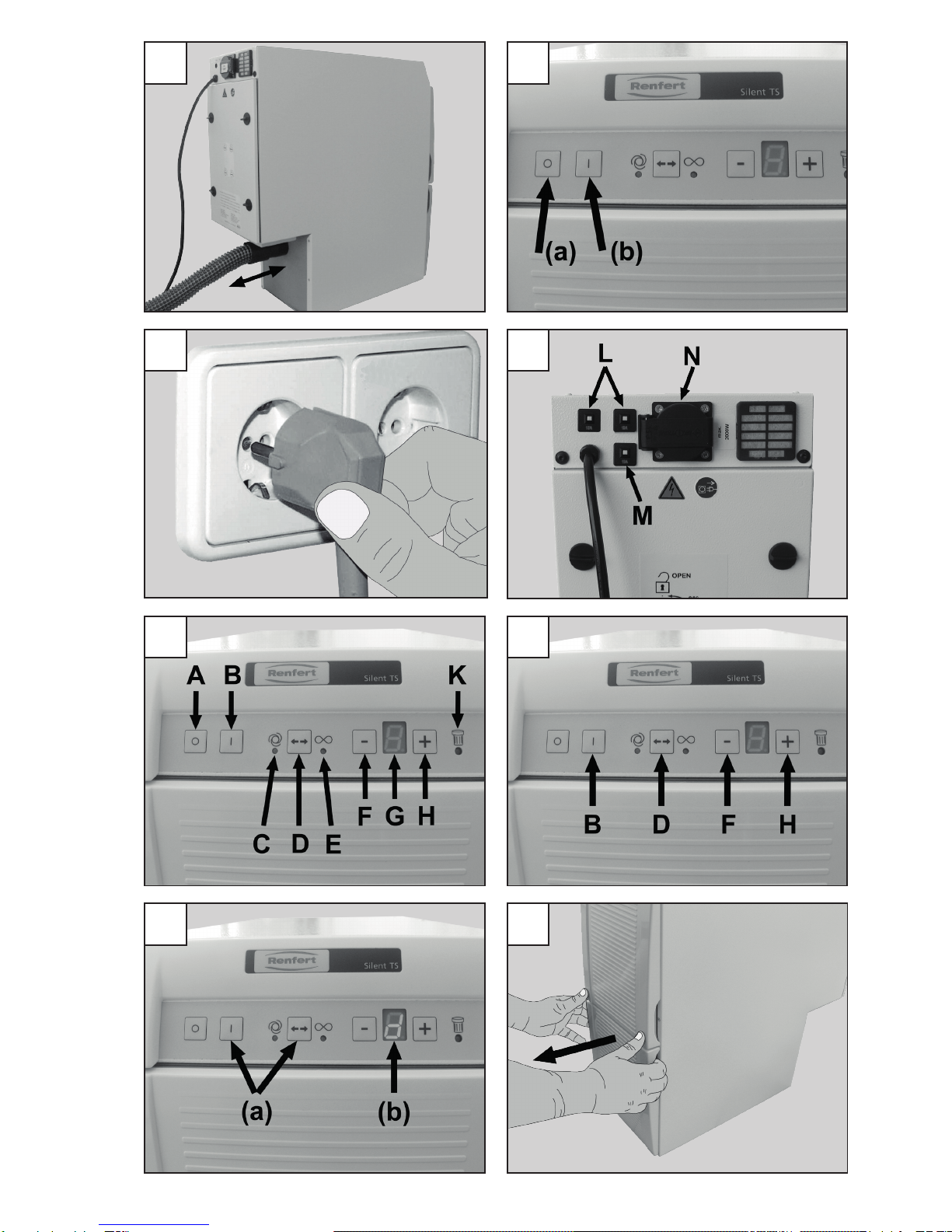
1. Setup and Commissioning............................2
1.1 Setup............................................................ 2
1.2 Connection to the Extraction Point............... 2
1.3 Electrical Connection ................................... 2
1.4 Connecting electrical equipment .................. 2
1.5 External Exhaust Air Route .......................... 3
2. Operation ......................................................3
2.1 Operating Elements .................................... 3
2.2 Switching the Unit ON / OFF........................ 3
2.3 Adjusting and Displaying the Extraction
Force ............................................................ 3
2.4 Continuous Operation ................................. 3
2.5 Automatic Mode ........................................... 4
2.6 Adjusting the Automatic Start Feature.......... 4
2.7 "Change Filter" - Indicator ............................ 4
2.7.1Adjustthesensitivityofthe„Replacelter“indicator...... 4
2.7.2Activating/deactivatingthe„Replacelter“indicator
tone ................................................................................ 4
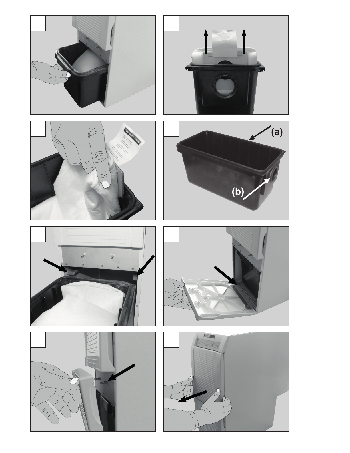
3. Cleaning / Maintenance ................................5
3.1 Seals ............................................................ 5
3.2 Replacing the Dust Bag ............................... 5
3.3 Filters ........................................................... 5
3.3.1 Replacing the Fine Particle Filter ................................... 5
3.3.2 Replacing the Exhaust Filter .......................................... 5
3.3.3 Replacing the Electronics Filter...................................... 6
3.4 Fuses ........................................................... 6
3.5 Self-diagnosis............................................... 6
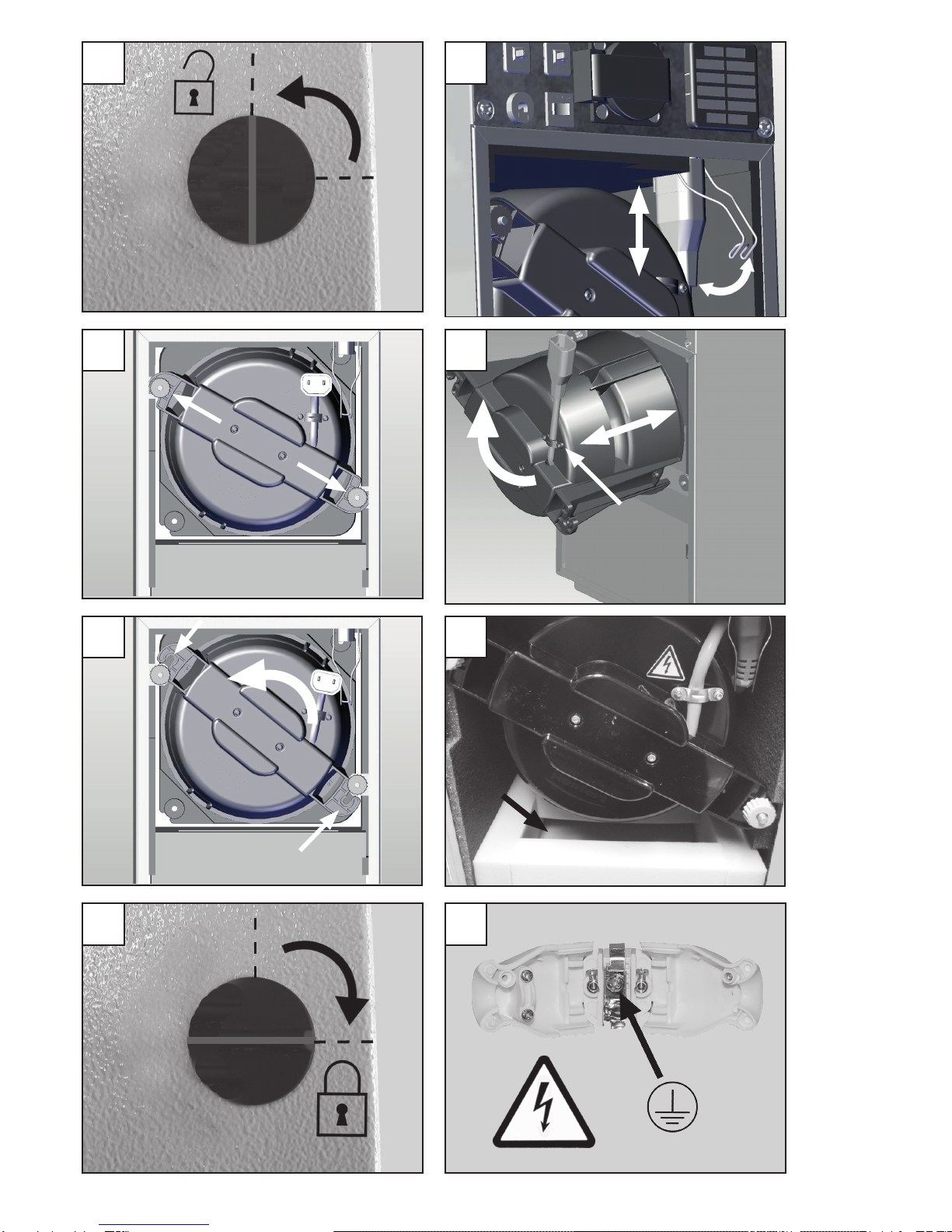
3.6 Replacing the Suction Turbine ..................... 6
3.7 Replacing the Exhaust Air Labyrinth ............ 7
4. Spare Parts...................................................7
5. Standard Delivery .........................................7
6. Delivery Versions ..........................................7
7. Accessories ..................................................7
8. Error List .......................................................8
Information for Operators
A. Application Area..........................................10
A.1 Proper Use ................................................. 10
A.2 Ambient Conditions
(in accordance with DIN EN 61010-1)........ 10
B. Hazard and Warning Information ................10
C. Authorised Individuals.................................11
D. Preparations Prior to Starting .....................11
D.1 Connecting the Dust Extractor ................... 11
D.2 Connecting a Dust-Generating Device....... 11
E. Repairs .......................................................11
F. Disposal Information ...................................12
F.1 Disposing of Consumables ........................ 12
F.2 Disposing of the Unit .................................. 12
F. 3 Disposal instructions for countries in
the EU ........................................................ 12
G.TechnicalSpecications..............................12
H. Liability Exclusion .......................................12
I. Warranty .....................................................12
Content

EN
- 2 -
Information for Operators
Using these operating instructions as a
starting point, instruct all operators of the
unit with regard to the area of application,
the possible hazards during operation, and
the proper operation of the dust extractor.
Please have these operating instructions readily
available for the operators.
Additional information can be found in the Section,
“InformationforOperators”,
at the end of these instructions.
Operating Instructions
1. Setup and
Commissioning
1.1 Setup
Remove the unit and all accessories from the ship-
ping package.
Inspect the delivery for completeness (refer to the
“StandardDelivery”Section).
The unit is fully operational upon delivery.
Select a setup location for the Silent TS
where the exhaust air vent is not blocked.
Where the unit is to be installed in a cabinet, an
opening with the following minimum dimensions must
be provided:
• Circular opening: Diameter at least 120 mm
• Rectangular opening: At least 170 x 65 mm.
The Silent TS is a free-standing unit intended to be
setupontheoor(e.g.,underaworkbench).
Particularly after installation of the roller
set (refer to the accessories list), the dust
extractor may only be operated if it is
standing on the oor.
1.2 Connection to the
Extraction Point
Use the included suction hose to connect the unit to
the extraction point.
• Push the suction hose onto the extractor connec-
tionttingonthedustextractor(g.1).
• Connect the suction hose to the desired extraction
point (e.g., Dustex master plus, extractor clamp,
etc.).
With the aid of an extractor switch or a Y-junction it is
possible to connect up to two suction points, or if nec-
essary, use a universal adapter for connector tubes
(seeaccessories).
Never operate the Silent TS without a suc-
tion hose.
Avoid steep pitches or hanging points
along the hose path. Never kink the hose
and make sure it is never stretched or
under tension when connected.
1.3 Electrical Connection
Before connecting the unit to the wall
outlet, make sure the voltage information
on the nameplate corresponds to your local
power supply.
Arrange conducting parts (mains outlets, plugs and
couplings)andinstallextensioncordsuchthatthe
protectionclass(IP)isretained.
• Unroll the power cord.
• PresstheOFFswitch(g.2A).
• Plugthepowercordintothewalloutlet(g.3).
The Silent TS is now ready for continuous
operation.
1.4 Connecting electrical
equipment
Electronic equipment (electrical dust-generating
equipment)canbeconnectedtotheSilent TS at the
couplersocketatthebackofthemachine(N,g.4).
In the automatic mode, extraction starts automatically
when a connected electric device is switched on.
Section D.2 at the end of these instructions offers
information concerning electrical systems employing
different power plug designs.
When connecting electrically operated
equipment to the dust extractor, please ob-
serve the operating instructions and safety
information provided with the equipment.
The unit power outlet is to be used only for
connecting electric, dust-generating devic-
es to be operated in conjunction with the
dust extractor.
The unit power outlet is live once the Silent
TS has been connected to the power supply
– even when the Silent TS is switched off.
This allows connected devices to be operat-
ed without extraction for brief periods.
Power consumption of all devices connect-
ed to the unit power outlet may not exceed
the rated value printed next to the unit pow-
er outlet.

EN
- 3 -
1.5 External Exhaust Air Route
Anexternalexhaustairroute(seeaccessories)al-
lows the extracted air to leave the laboratory.
The installation details are supplied with the external
exhaust air route.
When the extraction unit is used in conjunc-
tion with an external ventilation system, a
signicant quantity of air is extracted from
the room per hour.
This can create negative pressure within
the room which, when using an air depen-
dent naked ame fed by gas, liquid or solid
fuel, can cause poisonous gasses (e.g.
carbon monoxide) to be drawn into the
working area.
It is therefore essential to ensure that the
fresh air supply is sufcient and that the
environmental air pressure is maintained,
this should then be monitored by an autho-
rized specialist (e.g. a certied Gas Service
Engineer).
2. Operation
2.1 Operating Elements
Referalsotog.4,5
(A) OFFswitch
(B) ONswitch
(C) AutomaticmodeLEDindicator
(D) Continuous/automaticoperatingmode
selector switch
(E) ContinuousmodeLEDindicator
(F) Extractionforce/activationsensitivity
adjustment switch
8 (G) Extractionpower/activationsensitivity
display
(H) Extractionforce/activationsensitivity
adjustment switch
(K) "ChangeFilter"LEDindicator
(L) Mainsfuse(g4)
(M) Motorprotectionswitch(g.4)
(N) Unitplugsocket(g.4)
2.2 Switching the Unit
ON / OFF
The Silent TSisswitchedonattheONswitch(B)
(g.2b),andoffattheOFFswitch(A)(g.2a).
Extraction starts and stops in conjunction with the
selected operating mode (continuous operation or
automaticoperation).
The equipment‘s operating state is saved
once the suction unit has been operating
for longer than approx. 5 sec.
2.3 Adjusting and Displaying
the Extraction Force
The suction performance of the Silent TS can be
adjustedin4stagesbythebuttons(F)and(H).
This permits the unit’s performance to be precisely
matched to different types of materials being extract-
ed.
The extraction force setting is shown on the display
(G).
Increase the extraction force.
Decrease the extraction force.
2.4 Continuous Operation
ContinuousoperationLED(E)
In the continuous operation mode, the extractor will
begin running as soon as it is switched on, regardless
of other electrical equipment which may or may not
be connected.
Theoperatingmodeselectorswitch(D)isusedto
switchbetweenthe“continuous”and“automatic”
operating modes.
TheselectedoperatingmodeisindicatedbyLED(C)
orLED(E).
Continuous operating mode selection:
• Switch the Silent TS on
- LED comes on
- Continuous operation has now been selected
or
- LED comes on
- The automatic mode has been selected.
- Pressthe„D“key
- LED comes on
- Continuous operation has now been selected.
• The extractor will switch on.
TheextractorisstartedandstoppedwiththeON(B)
andOFF(A)switches.

EN
- 4 -
2.5 Automatic Mode
AutomaticMode,LED(C).
In automatic operation suction only starts when the
electric device connected is switched on responsible
is operated.
Selecting the automatic mode:
• Switch the Silent TSon(g.2b)
- LED comes on
- The automatic mode has been selected.
or
- LED comes on
- Continuous operation has now been selected
and the extractor starts.
- Pressthe„D“key
- LED comes on
- The automatic mode has been selected.
The extractor starts as soon as you begin operating
the dust-generating device.
After the dust-generating device is switched off, the
Silent TS continues to run for approx. 5 sec., then
stops automatically.
2.6 Adjusting the Automatic
Start Feature
In the automatic mode, the Silent TS is switched on
and off by an automatic start system.
This automatic start feature reacts to the current con-
sumed by an electronic equipment plugged into the
unitpoweroutlet(N,g.4).
If the current exceeds the activation threshold set at
the Silent TS, extraction starts. If the current drops
below this activation threshold, extraction stops.
The factory set parameter for the start-up
threshold enables the Silent TS to react cor-
rectly for most electrical dental equiment.
Should this not be the case for a particular
piece of equipment (eg. a handpiece), then
the start-up threshold can be adjusted ac-
cordingly.
To change the activation threshold:
1. Switch Silent TS on.
2. Press and hold for 3 sec.;
- LED and ash.
- A“0”ashesonthedisplay.
3. Switch electronic equipment off. For units
equipped with a standby mode, switch them to this
mode (e.g., for units equipped with handpieces,
only switch the controller on without activating the
handpiece).
4. Press the key.
- A“1”ashesonthedisplay.
5. Switch the electrical appliance on, i.e. activate the
hand piece at the speed at which the Silent TS is
required to start up.
6. Press the key
- Anaudiblesignalconrmsthattheadjustment
has been successfully performed.
The Silent TS returns to the operating mode (contin-
uousorautomaticoperation)whichwassetforthe
automatic start function prior to the adjustment.
2.7 "Change Filter" - Indicator
LED(K)comingonindicatesthateitherthedustbag
ortheneparticlelterneedstobereplaced.
An acoustic signal will also sound three times in this
case. In this case, follow the instructions given in the
“Cleaning/Maintenance”sectiontoreplacethedust
bagortheneparticlelter.
If the dust extractor continues to be used
after the “Change Filter” indicator goes on,
it will automatically stop once the airow
drops below a predened minimum value.
The LED display blinks (K).
The indicator can be turned off by switching
the Silent TS OFF and ON, thus restarting
extraction.
Operating the unit with a blocked ltration
system can result in hazards and damage to
the extractor. Filters must be replaced if the
extractor stops due to a full lter.
2.7.1 Adjust thE sEnsitivity of thE „rEplAcE
filtEr“ indicAtor.
It may be necessary to reduce responsivi-
ty if the suction support of the connected
appliance has a smaller diameter than the
Silent TS. (<< 32.5 mm).
The„Replacelter“sensitivitycanbeadjustedwithin
limits.
To do this:
• Switch the Silent TS off;
• Switch the Silent TS on, and in doing so keep the
buttonrmlypresseduntilthedisplaybeginsto
blink.(5=factorysetparameter)
• Press button ,
- Reduce level of sensitivity,
- „Changelter“signalwillappearlater.
- ==> Dust bag will get very full
• Press button ,
- Increase level of sensitivity,
- „Changelter“signalappearsmorequickly.
- ==> Dust bag will get less full
• Press button ,
- Accousticsignalconrmssuccessful
adjustment.
2.7.2 ActivAting / dEActivAting thE „rEplAcE
filtEr“ indicAtor tonE
The„Replacelter“indicatortonecanbeactivatedor
deactivated.
To do this:
• Switch the Silent off;
• While holding down the and keys, switch
the Silent back on and wait for the indicator tone
- Brief indicator tone: acoustic signal deactivated.
- Longer indicator tone: acoustic signal active.

EN
- 5 -
3. Cleaning / Maintenance
Always unplug the unit from the wall outlet
before beginning any cleaning or mainte-
nance tasks.
Examine the power cord regularly, but at
least annually, for damage or signs of
aging. Immediately replace damaged power
cords.
3.1 Seals
To ensure the proper function of the dust extractor, it
is vital that the following three seals:
•Prolesealonthedustdrawer(g.12a);
•V-ringsealonthedustdrawer(g.12b);
•Sealontheupperfrontpanel(g.20);
are not damaged.
Inspect these seals when replacing the associated
ltersandreplacethemiftheyarefoundtobe
damaged(refertothesparepartslist).
3.2 Replacing the Dust Bag
The dust extractor may only be operated with a
completeltrationsystem.Thedustbagmustbe
immediately replaced with a new one as soon as the
“ChangeFilter”indicatorgoeson.
Failure to replace the dust bag may result
in it’s rupturing. Depending on the material
in the bag, this may lead to hazards for the
operator. In addition, the dust extractor may
be damaged.
• Pullthefrontpanelforwardandoff(g.8).
• Pullthedustdrawerouttowardsthefront(g.9).
• Leave the dust bag in the dust drawer and take it to
the disposal location.
• Remove the dust bag from the drawer.
• Takeoffprotectionlm,coverlteropening(g.10).
• Dispose the dust bag accordingly.
Always comply with all local ordinances
governing proper disposal and accident
prevention!
Depending on the lter contents, protective
clothing may be required.
• Insert the new dust bag into the dust drawer, being
careful to ensure that the dust bag is properly
aligned in the guide grooves and the glue lap faces
up(g.11).
Use only original Renfert dust bags
(refer to the spare parts list).
• Inspect the dust drawer seal for damage and
replaceit,asrequired(g.12a,b).
• Insert the dust drawer, making sure it is straight,
and push it fully against its stops. Make sure the
dust drawer is seated correctly on the guide
(g.13).
• Installthefrontpanelonthebottomhooksrst
(g.14),thenpushitintotheupperlockbolts,
pressingrmlyuntilitlocksinplace(g.15).
3.3 Filters
NEVER operate the dust extractor without
the complete ltration system.
3.3.1 rEplAcing thE finE pArticlE filtEr
Examinetheneparticlelterregularly,butatleast
annually, and replace it. It must always be replaced if
the“ChangeFilter”indicator(K)continuestogoon,
despite the dust bag having been replaced.
• Pullthefrontpanelforwardandoff(g.16).
• Turntheneparticlelteranticlockwisetoreleaseit
(g.17).
• Pulltheneparticlelterstraightforwardsandout
oftheunit(g.18)anddisposeofitproperly.
Always comply with all local ordinances
governing proper disposal and accident
prevention!
Depending on the lter contents, protective
clothing may be required.
• Installanewnelterandfullyinsertitoverthe
holderbar(g.19).
Use only original Renfert ne particle lters
(refer to the spare parts list).
• Turntheneparticlelterclockwiseandhand-tight-
enitinplace(g.17).
• Inspect the seal on the front panel for damage and
replaceit,asrequired(g.20).
• Snapthefrontpanelinplace(g.21,22).
3.3.2 rEplAcing thE ExhAust filtEr
Theexhaustlterprimarilytrapsparticlesrubbedoff
thesuctionturbinegraphitebrushes.Theltershould
be replaced annually:
• Pressonthefourlocktabsontheltercassette
and pull the cassette down and off the unit
(g.23).
• Properlydisposeofthelterandtheltercassette.
Always comply with all local ordinances
governing proper disposal and accident
prevention!
Depending on the lter contents, protective
clothing may be required.
• Insertanewltermatintheltercassettesothat
thesmooth,compressedsideoftheltermatfaces
downoroutwardswhenthelterisinstalled.
• Installthenewltercassetteontheexhaustair
vent.
• Makesuretheltercassetteisproperlyseatedand
locked in place on all four tabs.
Use only original Renfert exhaust lters
(refer to the spare parts list).

EN
- 6 -
3.3.3 rEplAcing thE ElEctronics filtEr
Cooling air for the unit’s electronics passes through
theelectronicslter.Thetypeofmaterialtrappedby
thelterandthedegreeofcontaminationdependon
the ambient laboratory conditions.
Theltershouldbeexaminedannuallyandreplaced,
as necessary:
• Pressonthetwolocktabsontheltercassetteand
pull the cassette off towards the rear of the unit
(g.24).
• Properlydisposeofthelterandtheltercassette.
Always comply with all local ordinances
governing proper disposal and accident
prevention!
Depending on the lter contents, protective
clothing may be required.
• Installanewltercassetteandlteronthe
opening.
• Makesuretheltercassetteisproperlyseatedand
locked in place on both tabs.
Use only original Renfert electronics lters
(refer to the spare parts list).
3.4 Fuses
Instead,twodeviceoverloadswitches,(L,g.4)are
provided to protect these units.
Press the button to reset a switch which has tripped.
3.5 Self-diagnosis
The dust extractor is equipped with a self-diagnosis,
which checks various functions and displays errors
onthedisplay(G).
Before the diagnosis takes place, insert a
new dust bag and ensure that the ne lter
is clean and the suction pipe is not blocked.
Activate the self-diagnosis:
• Switch Silent TS off;
• Press and hold the operating mode selector switch
(D)andswitchSilent TSon(g.7a).
• For approx. 3 sec.:
- all LED displays are illuminated,
- An„8“isindicatedinthedisplay
- The signalling device gives an acoustic signal.
• A“d”appearsonthedisplayduringtheunit’sself-
test(g.7b).Duringthistime,theunit’selectronics
check various internal elements and functions. The
suctionturbineswillbrieyrunatLevel1duringthis
test phase.
• If no errors are detected, the Silent TS automatical-
ly goes into the previously selected
operating mode at the end of the self-test
(afterapprox.10sec.).
• Ifanerrorisdetectedduringtheself-test,aashing
“E”willappearonthedisplay,togetherwithanum-
ber(1to3).
These indicate:
E1: Airowsensorfault;havetheunitrepaired.
E2: Plug on grey motor wire out of its socket
(g.26)orsuctionturbinefault.Replace
suction turbine if necessary (refer to the spare
partslist).
E3: Error in the electronics; have the unit repaired.
In this case, the Silent TS remains in the
self-diagnosis mode until it is switched off at the
OFFswitch(A).
3.6 Replacing the Suction
Turbine
The suction turbine is encased in an encapsulating
housing to form a single unit, thus allowing it to be
easily replaced without the need for any tools.
Before opening the unit, disconnect it from
the mains power supply by unplugging the
power cord from the wall outlet.
The motor may be hot. Allow the motor to
cool off before proceeding.
The suction turbine may only be operated
when it is installed in the unit. Only an au-
thorized electrician may perform a function-
al inspection of or repair the unit.
• Turnthelockknob90°anticlockwise(g.25).
• Remove the motor compartment cover.
• Openthexingclipandremovethemotorplug
(g.26).
• Loosen the two internal, grey knurled nuts
(g.27)andunscrewthemapprox.1cm.These
knurled nuts do not need to be completely re-
moved.
• Release the suction turbine by turning it anticlock-
wise, then pull it straight out towards the back
(g.28).
• Installthenewsuctionturbine(g.28)bypushingit
in straight and turning it clockwise to lock it in place
(g.29).Theconnectingwireshouldbeontop
(g.28a).
• Tightentheinternalknurlednuts(g.27).
• Insertthemotorplugandclosethexingclip
(g.26).
• Check that the lock knob is in the open position
(vertical).
• Place the motor compartment cover on the motor
compartment. Two guide pins have been provided
on the cover to assist in positioning it correctly.
• Turnthelockknob90°clockwise(g.31).
Always comply with all local ordinances
governing proper disposal and accident
prevention!

EN
- 7 -
3.7 Replacing the Exhaust Air
Labyrinth
Dust from the suction turbine graphite brushes also
settles on the walls of the exhaust air labyrinth. Over
time, the labyrinth will become discoloured.
Before opening the unit, disconnect it from
the mains power supply by unplugging the
power cord from the wall outlet.
Replacing the exhaust air labyrinth:
• Turnthelockknob90°anticlockwise(g.25).
• Remove the motor compartment cover.
• Pull the exhaust air labyrinth out towards the back.
• Install the new exhaust air labyrinth by pushing it
in straight, making sure it is properly seated. The
openings in the exhaust air labyrinth must face
towardstherear(g.30).
• Check that the lock knob is in the open position
(vertical).
• Place the motor compartment cover on the motor
compartment. Two guide pins have been provided
on the cover to assist in positioning it correctly.
• Turnthelockknob90°clockwise(g.31).
Always comply with all local ordinances
governing proper disposal and accident
prevention!
4. Spare Parts
Youcanndcomponentssubjecttowearandthe
spare parts on the spare part list in the internet at
www.renfert.com/p918.
The components excluded from the warranty (such
asconsumablesorpartssubjecttowearandtear)
are marked on the spare part list.
Serial number and date of manufacturing are shown
on the type plate of the unit.
5. Standard Delivery
1 Silent TS laboratory dust extractor
1 Operating instructions
1 Suction hose
1 Dustbag(properlyinstalledinthedustdrawer)
1 Fineparticlelter(properlyinstalled)
1 Hosettingadapter
1 Y-junction
1 Groundedwallplug(No.2921-0050only)
6. Delivery Versions
2921-0050 Silent TS, 230 V, 50/60 Hz
2921-1050 Silent TS, 100 - 120 V, 50/60 Hz
7. Accessories
2921-0002 Dustbagset(5bags)
2921-0001 Rollerset
2925-0000 Extractorclamp(w./o.glasspane)
2925-1000 Glasspane,w.mounting
(fortheextractorclamp)
2926-0000 Suctionswitch,incl.4mufers
(w./o.hose)
2921-0003 Muferset,2mufers
2921-0004 Externalexhaustaircontrol
2934-0007 90°angledconnectorSilent
15-0823 Suctionhose(bythemetre)
90003-4305 Hosettingadapter
90003-4240 Suctionhose(3m),cpl.
900034826 Suctionhose,antistatic,3m,incl.
2endmufers
90003-4314 Y-junction
90003-4410 H+HepalterSilent TS

EN
- 8 -
8. Error List
Error Possible cause Corrective action
Dust extractor stops
suddenly, for no apparent
reason.
• Dust extractor continued to be
used,despite“ChangeFilter”
indicator.
• Unit fuse blown.
• Motorprotectionswitch(M,g.4)
has been activated due to overload
(temperature,electricity).
• Motor over-temperature protector
switch activated.
• Plug on grey motor wire out of its
socket or loose.
• Suction turbine fault.
• In-house fuse blown.
• Checkandreplacethedustbagandneparticle
lter(Chapter3.2and3.3).
• Check and reinstall the fuse.
• Check the motor protection switch, if necessary
reset.
• Change the motor if repeatedly activated.
• Checkdustbagandlter,replaceasrequired.
(Sec.3.2and3.3).
• Checkexhaustairlter,replaceasrequired.
(Sec.3.3.2).
• Check whether suction hose is blocked. Remove
obstruction as required.
• Dust extractor can be restarted after being allowed
to cool off for approx. 1 hour.
• Checkplug(g.26).
• Carryoutself-diagnosis(chapt.3.5),atfault„E2“
exchangesuctionturbine(seesparepartslist).
• Replace the in-house fuse.
• Check the total power consumption of the dust
extractor plus dust-generating devices.
Dust extractor stops
suddenly, for no apparent
reason. E4 is indicated on
the display.
• The electronics may be overheated
due to excessively high ambient
temperature, e.g., if the unit is
installed in a cabinet.
• Allow the extractor to cool down.
• Attempt to improve the ventilation conditions. Refer
also to Sec. 1.1.
After switching on the
unit, the display immedi-
ately indicates E4.
• Temperature sensor fault.
• After overheating, the device has
notyetcooleddownsufciently.
• Have the device repaired.
• Disconnect the device and let it continue to cool
down.
The self-test returns a
suction turbine error,
even though the turbine
is running.
• Filter full.
• Suction hose blocked.
• Suction turbine fault.
• Checkdustbagandneparticlelter,replaceas
required.(Sec.3.2and3.3.1).
• Remove obstruction from the suction hose.
• Replacethesuctionturbine(Sec.3.6).
Insufcient extraction
force.
• Extraction force level too low.
• Filter blocked.
• Suction hose blocked.
• Dust drawer seal not tight.
• Upper front panel fails to close
properly.
• Suction hose damaged.
• Increasetheextractionlevel(Sec.2.3).
• Checkdustbagandneparticlelter,replaceas
required.(Sec.3.2and3.3.1).
• Remove obstruction from the suction hose.
• Check the proper seat of the dust drawer
(Sec.3.2).
• Check the dust drawer seal for damage and
replaceasrequired(Sec.3.1).
• Check the proper seat of the upper front panel
(Sec.3.3.1).
• Check the upper front panel seal for damage and
replaceasrequired(Sec.3.1).
• Inspect the suction hose and replace as required.

EN
-9-
Error Possible cause Corrective action
“Change Filter” indicator
goes on shortly after
lters were replaced.
• Fineparticlelterblocked.
• Suction hose blocked.
• Cross-section of the dust-
generatingdevice’shosettingis
too small.
• Dustistoone.
• Flow sensor defect.
• Replacetheneparticlelter(Sec.3.3.1).
• Remove obstruction from the suction hose.
• Adjustthesensitivityofthe„Replacelter“
indicator(Chapter2.7.1.).
• Adjustthesensitivityofthe„Replacelter“
indicator(Chapter2.7.1.)
• Carryoutself-diagnosis(chapt.3.5),atfault„E1“
equipment requires professional repair.
Dust bag ruptures. • The“ChangeFilter”indicator’s
sensitivity has not been adjusted
for the material being extracted.
• Reducethesensitivityofthe„Replacelter“
indicator(Chapter2.7.1.).
Dust extractor fails to
start when a dustgenerat-
ing device is being used.
• Dust extractor not switched on.
• Dust-generating device not
plugged into the unit power outlet
on the Silent TS.
• Wrong operating mode selected.
• Automatic start feature’s threshold
value too high.
• Device fuse has blown.
• Automatic start feature fails to
detect the attached device’s
operation.
• Switchthedustextractoron(Sec.2.2).
• Connect the dust-generating device to the Silent
TS(Sec.1.4).
• Selecttheautomaticmode(Sec.2.5).
• Adjusttheautomaticstartfeature(Sec.2.6).
• Checkandreinstallthefuse.(Sec.3.4).
• Some older handheld instruments do not generate
asufcientlystrongsignalfortheautomaticstart
feature. Switch the dust extractor to the continuous
mode.
Dust extractor starts,
although a connected
device is not being used.
• Automatic start feature’s threshold
value too low.
• Adjusttheautomaticstartfeature(Sec.2.6).
Dust extractor fails to
stop when a connected
device is switched off.
• Dust-generating device not
plugged into the unit power outlet
on the Silent TS.
• Wrong operating mode selected.
• Activation threshold too low.
• Connect the dust-generating device to the Silent
TS(Sec.1.4).
• Selecttheautomaticmode(Sec.2.5).
• Adjusttheautomaticstartfeature(Sec.2.6).
No satisfactory setting
of the automatic start
feature can be adjusted.
• Some older handheld instruments
donotgenerateasufciently
strong signal for the automatic
start feature.
• Switch the dust extractor to the continuous mode.
Extraction briey starts
up when the unit is
switched on.
• Activation sensitivity too low. • Adjusttheautomaticstartfeature(Sec.2.6).
Panels covering the ne
particle lter and the dust
drawer are difcult to
open.
• Lock bolts dirty. • Clean the lock bolts and lubricate them slightly, if
required.

EN
- 10 -
Information for Operators
The following information is intended to assist you,
the operator, in safely working with the Silent TS in
your laboratory.
Using these operating instructions as a
starting point, instruct all operators of the
unit with regard to the area of application,
the possible hazards during operation, and
the proper operation of the dust extractor.
Please have these operating instructions readily
available for the operators.
A.Application Area
The Silent TS is a workbench extractor used to ex-
tract dusts such as occur in laboratories, e.g., dental
labs.
It is solely intended for commercial use in laboratories
and not for private, household use.
The Silent TS can be operated both manually as well
as in conjunction with connected, electric, dust-gener-
ating equipment.
It is possible to connect one or two suction points
to the extractor. The second suction point can be
connected with a Y-adapter which is available as an
accessory(seechapter„accessories“).
In order to protect the health of persons
working in a dental laboratory, the law re-
quires that specialised dust extractors must
be used.
National regulations state the MAK value
- maximum concentration of suspended
particles in the air.
Find out about the legal national threshold
value and the type of dust generated in
your laboratory.
A.1 Proper Use
Proper use implies the extraction of dry, non-explo-
sivedusts.Fire-promoting,easilyammable,amma-
ble, or explosive materials may not be extracted with
the Silent TS.
The extraction of liquids, smouldering, or burning
materials is prohibited.
Anyotheruseisnot„asintended“.Themanufacturer
shall not be liable for any damages resulting from any
such other use.
The„useasintended“includescompliancewiththe
operating, servicing and preventive maintenance
conditionsdenedbythemanufacturer.
A.2 Ambient Conditions
(in accordance with DIN EN 61010-1)
The unit may only be operated:
• Indoors;
• Up to an altitude of 2,000 m above sea level;
• At an ambient temperature range between
5-40ºC[41-104ºF]*);
• At a maximum relative humidity of 80 % at 31 ºC
[87.8 ºF], dropping in a linear manner to 50 %
relativehumidityat40ºC[104ºF]*);
• Withmainspowerwherethevoltageuctuations
do not exceed 10 % of the nominal value;
• Under contamination level 2 conditions;
• Under over-voltage category II conditions;
*)Between5–30°C[41–86°F],theunitcanbeoperatedat
a relative humidity of up to 80 %. At temperatures between
31–40°C[87.8–104°F],thehumiditymustdecreasepropor-
tionallyinordertoensureoperationalreadiness(e.g.,at35°C
[95°F]=65%humidity;at40°C[104°F]=50%humidity).The
unitmaynotbeoperatedattemperaturesabove40°C[104°F].
B.Hazard and Warning
Information
Only intended for indoor use. The unit is
only designed for dry applications and may
not be operated or stored outdoors or un-
der wet conditions.
The Silent TS laboratory dust extractor is an
electric device and, as such, carries with it
a certain inherent potential hazard. The unit
may not be taken into service until any re-
quired alterations to comply with regionally
specic power plug congurations have
been made. Such alterations may only be
performed by a qualied electrician.
The unit may only be operated if the infor-
mation on the nameplate conforms with the
specications of your local mains power
supply.
The mains socket on the unit is only de-
signed for the purposes specied in the
Operating Instructions. Connecting other
devices may cause material damage. Before
connecting another device, turn off both the
dust extractor and the other device.
Read the operating instructions of the other
device and comply with the safety instruc-
tions contained in the document.
Please observe the national regulations and
permitted exposure to dust in a working
environment. Please note EN 60335-2-69,
Appendix AA, or initiate appropriate en-
quiries with your trade association or the
responsible authorities.
When extracting hazardous materials,
always refer to the relevant safety data
sheets.
Always wear protective gear when extract-
ing hazardous materials.
It is necessary to wear suitable, personal
protective equipment when emptying the
dust bag or cleaning, depending on the type
of extracted material.

EN
- 11 -
Regularly inspect connecting lines and hos-
es (e.g., the power cord) for damage (e.g.,
kinks, cracks, porosity) or signs of aging.
Units exhibiting damaged connecting lines,
hoses, or other defects must be taken out
of service immediately.
Always unplug the unit from the wall outlet
before beginning any work on the unit’s
electrical components.
Never operate the unit without the complete
ltration system (dust bag, ne particle
lter, exhaust air lter, electronics lter).
Make sure the dust drawer is fully closed
during extraction.
Never operate the unit without the suction
hose.
Never extract ammable or explo-
sive gases, vapours, dusts.
Never extract liquids.
Never extract hot materials.
The unit may not be operated without
supervision.
All required tools must be appropriately
cleaned prior to use when the unit is
employed for medical purposes or in con-
junction with medicinal materials.
If the dust extractor is employed to extract
hazardous materials, appropriate personal
protective gear must be worn and steps
must be taken to ensure that the exhaust
air is properly ventilated. Please refer to the
associated safety data sheets for specic
requirements.
Environmentally hazardous extraction
substances. Extracted substances may be a
risk to the environment.
Dispose of extracted material according to
local statutory regulations.
It is the responsibility of the operator that
national regulations during operation and
regarding a repeated safety inspection of
electrical equipment are complied with.
For Germany these are the regulation 3 by
DGUV (German Statutory Accident Insur-
ance) in relation with VDE (Association for
Electrical & Electronic Technology) 0701-
0702.
Only spare parts and accessories supplied
or authorized by Renfert GmbH may be
used with this product. If other spare parts
or accessories are used, this could have a
detrimental effect on the safety of the de-
vice, increase the risk of serious injury and
lead to damage to the environment or the
device itself.
C.Authorised Individuals
Only properly trained individuals may operate and
service the Silent TS.
Minors or pregnant women may only operate and
service the Silent TS if they are wearing appropriate
protective gear, particularly if the unit is being used to
extract hazardous materials.
Anyrepairsnotspecicallydescribedintheseoperat-
ing instructions, in particular the inspection of the suc-
tion turbine outside the unit, may only be performed
byaqualiedelectrician.
D.Preparations Prior to
Starting
D.1 Connecting the Dust
Extractor
The unit is supplied with a power cord and two-con-
tactplugwithagroundcontact(eitherDIN49441or
NEMA, depending on the particular model in ques-
tion).
The unit may not be taken into service until any
requiredalterationstocomplywithregionallyspecic
powerplugcongurationshavebeenmade.
Such alterations may only be performed by a quali-
edelectrician.
The unit may only be connected to wall outlets con-
nected to a ground circuit system.
Before operating the unit, make sure the voltage in-
formation on the nameplate corresponds to your local
power supply.
D.2 Connecting a Dust-
Generating Device
The unit is equipped with a power outlet on the back,
designed for a two-contact plug with a ground contact
(eitherinaccordancewithDIN49441orNEMA),to
which dust-generating equipment can be connected
(N,g.4).
A suitable plug is supplied for units with a nominal
voltage of 230V and plug socket according to
DIN49441(Fig.32).Thisconnectorcanbeusedto
makeanadapterforyourlocalplugconguration.
This adapter may only be made by a quali-
ed electrician!
The adapter must not interrupt the ground
circuit system!
E. Repairs
Repairsmayonlybeperformedbyqualiedelectri-
cians or authorized dealers.
Dependingonthematerialtrappedbythelters,
protective gear may need to be worn during repairs.

EN
- 12 -
We reserve the right to make technical changes.
F. Disposal Information
F.1 Disposing of Consumables
Fulldustbagsandlters–includingmotorand
electronicslters–mustbedisposedofundercom-
pliance with locally applicable regulations.
Dependingonthematerialtrappedbythelters,pro-
tective gear may need to be worn during disposal.
F.2 Disposing of the Unit
The unit must be disposed of by an authorized recy-
clingoperation.Theselectedrmmustbeinformed
of all possibly health-hazardous residues in the unit.
F.3 Disposal instructions for
countries in the EU
To conserve and protect the environment, prevent
environmental pollution and improve the recycling of
raw materials, the European Commission adopted
a directive that requires the manufacturer to accept
the return of electrical and electronic units for proper
disposal or recycling.
Within the European Union units with this symbol
should not therefore be disposed of in unsorted do-
mestic waste:
For more information regarding proper disposal
please apply at your local authorities.
G. Technical Specications
Mains voltage: 220 - 240 V, 50/60 Hz
100 - 120 V, 50/60 Hz
Dust extractor power
consumption: 1400W(230V)
1400W(120V)
1000W(100V)
Unit power outlet maximum
connectingvalue: 2000W(230V)
360W(120V)
500W(100V)
Totalconnectedpower: 3400W(230V)
1800W(120V)
1500W(100V)
Mainsinputfuse(g.4,L): 2x15A(T)
LpA*)(atmax.volumeow): 63dB(A)
Volumeow,max.: 3300l/min(120V/230V)
2900l/min(100V)
Vacuumpressure,max.: 200hPa[2.9psi]
Filter surface area,
neparticlelter,approx.: 0.8m²/[1240sqinch]
Fill volume, dust bag, approx.: 7.5 l [2 US gal]
Dimensions
(widthxheightxdepth): 224x591x564mm
[8.8 x 23.3 x 22.2 inch]
Weight(empty),approx.: 26kg[57lbs]
ØSuctionttings:
Internal: 32 mm [1.26 inch]
External: 40 mm [1.57 inch]
*)Soundpressurelevelinaccord.withENISO11202
H.Liability Exclusion
Renfert GmbH shall be absolved from all claims for
damages or warranty if:
• The product is employed for any purposes
other than those cited in the operating instruc-
tions;
• The product is altered in any way other than
those alterations described in the operating
instructions;
• The product is repaired by other than an autho-
rized facility or if any but Renfert OEM parts are
employed;
• The product continues to be employed, despite
obvious safety faults or damage;
• The product is subjected to mechanical im-
pacts or is dropped.
I. Warranty
Provided the unit is properly used, Renfert warrants
all components for 3 years.
The suction motor has a guarantee of 3
years, with a maximum of duration of 1000
operating hours (motor running time).
Warranty claims may only be made upon presenta-
tion of the original sales receipt from the authorized
dealer.
Parts which are subject to natural wear and tear
(wearparts)andconsumablesareexcludedfromthe
guarantee. These parts are marked in the spare part
list.
The warranty is voided in case of improper use; fail-
ure to observe the operating, cleaning, maintenance,
and connection instructions; in case of independent
repairs or repairs by unauthorized personnel; if spare
parts from other manufacturers are employed, or; in
caseofunusualinuencesorinuencesnotincom-
pliance with the utilization instructions.
Warranty service shall not extend the original warran-
ty.

Renfert GmbH • Industriegebiet • 78247 Hilzingen/Germany
Tel.: +49 7731 82 08-0 • Fax: +49 7731 82 08-70
Renfert USA • 3718 Illinois Avenue • St. Charles IL 60174/USA
Tel.: +1 6307 62 18 03 • Fax: +1 6307 62 97 87
USA: Free call 800 336 7422
Hochaktuell und ausführlich auf ...
Up to date and in detail at …
Actualisé et détaillé sous …
Aggiornato e dettagliato su …
La máxima actualidad y detalle en ...
Актуально и подробно на …
www.renfert.com
Ideas for dental technology
This manual suits for next models
1
Table of contents
Other Renfert Vacuum Cleaner manuals

Renfert
Renfert Dustex master plus Installation guide

Renfert
Renfert Silent User manual

Renfert
Renfert Vortex compact 3L User manual

Renfert
Renfert Dustex master plus User manual

Renfert
Renfert Vortex compact 3L User manual

Renfert
Renfert Vortex compact 3L User manual

Renfert
Renfert Vortex compact 2 L User manual

Renfert
Renfert Dustex master plus User manual

Renfert
Renfert SILENT compact Operating and installation instructions

Renfert
Renfert Silent V4 Operating and installation instructions