First :
• Install the Arduino soware (1.0.6 version or lower). You can download it from our website or the ocial Arduino’s website.
Aer that, the RAMPS board must be connected on the Arduino board.
• Connect USB (do not connect the power supply).
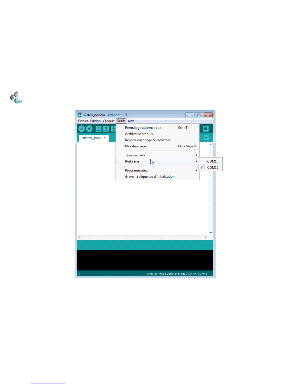
• Check if the board is identied by your computer. You can to push on « Windows + Pause » -or go to your compute setup-, and on « Device manager »
on the le. e Arduino Mega 2560 board must appeared in the device list.
System panel of Windows Device manager
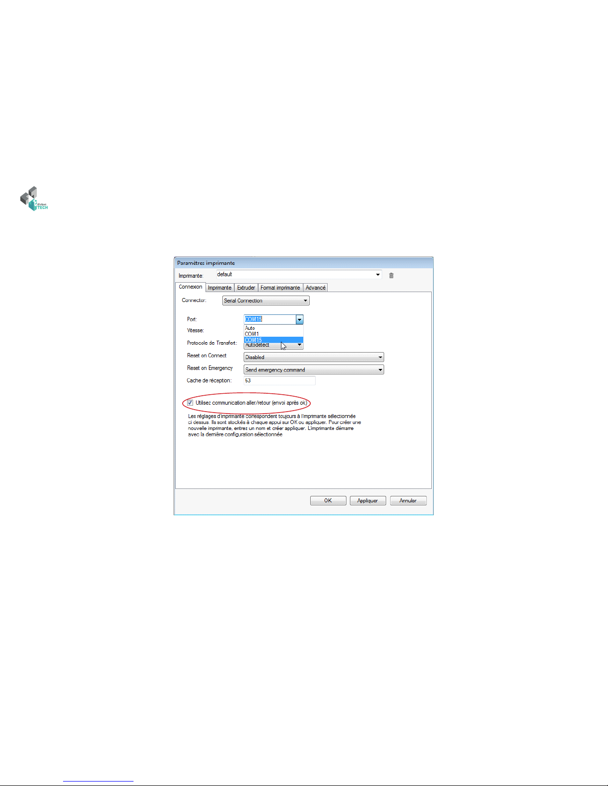
Read the COM port of your Arduino board (Arduino Mega 2560)
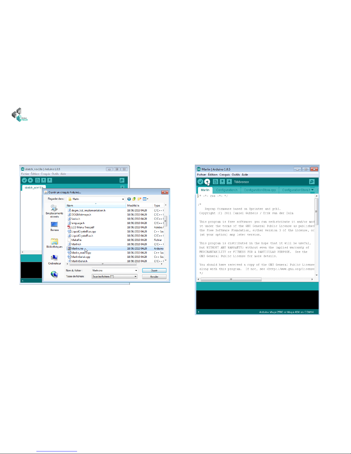
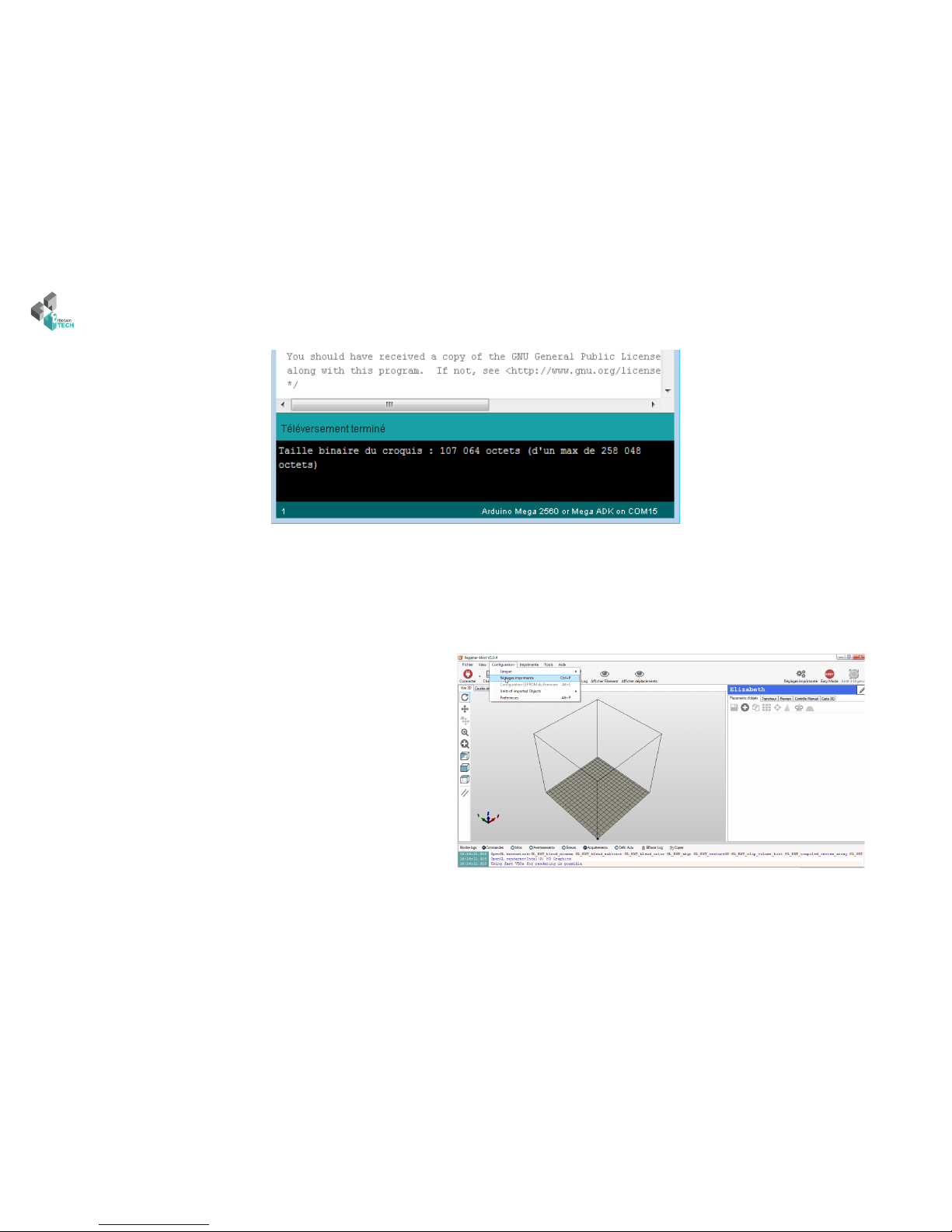
Driver and the rmware installation
Note : If Windows 8 or higher is installed on your PC, you should deactivated automatic control of unsigned drivers. It’s possible to nd process about
this on the web.
If it is not regognized, please install drivers manually by doing a right-click on it. Arduino’s drivers is in the Arduino «drivers» folder.