manuals.online logo
Brands
  1. Home
  2. •
  3. Brands
  4. •
  5. resideo
  6. •
  7. Controllers
  8. •
  9. resideo aube CT240 Manual

resideo aube CT240 Manual

The CT240 telephone controller is designed to remotely control your
home’s thermostat. It is possible to command a temperature
decrease (Unoccupied) during a prolonged absence or a temperature
increase (Comfort) before you return home.
Depending on your thermostat’s operating characteristics, it either
connects to the Aube output (for most Aube models) or to the auxil-
iary output.
When the auxiliary output is not used to control a thermostat, it can
be used to simultaneously control a load such as a water heater,
lighting, etc.
)LJXUH
ЛнкЯрЮпϫКсансдатϫ
Any device connected to a telephone line must conform to the coun-
try's standards. The CT240 telephone controller meets:
• FCC68 standards for installation on the North American network.
• FDTBR21 standards for installation on the European network.
2.1 Included Parts
• One CT240 telephone controller
• One power transformer 120 V (North America) or 250 V (Europe)
• One 5 m (16 foot) telephone cable
NOTE: If you are using an answering machine, position the answer-
ing machine switch to ON before installing the CT240.
Make sure that your answering machine answers after a minimum of
4 rings.
)LJXUH
ЌйотандйвϫИЬЮгдйаϫОтдпЮг
)LJXUH 
ПфлдЮЬзϫДйопЬззЬпдкй
nMount the CT240 near a telephone outlet.
NOTE: If you plan to connect a load having more that 30 volts on the
auxiliary output, the CT240 must be installed inside a certified electri-
cal box.
oOPTIONAL. Connect your phone (or answering machine) to the
PHONE connector of the CT240.
pConnect one end of the telephone cable to the LINE connectorof
the CT240 and the other end to the telephone outlet in your
home.
qConnect the thermostat and load. Both outputs work simulta-
neously.
NOTE: Refer to your thermostat’s electrical specifications (telephone
interface) for the connection requirements.
• If your thermostat requires a 12 VDC signal to switch to Vaca-
tion setpoint, use the ABC output (FIGURE 4):
A and C terminals:
• 0 VDC in Comfort mode
• 12 VDC in Vacation mode
NOTE: 50 mA max. for parallel connection of Aube thermostats.
• If your thermostat requires a dry contact to switch to the Vaca-
tion setpoint, use the 123 output (FIGURE 5):
• Load = terminals 2 and 3 (NC) (open = Vacation)
• Thermostat = terminals 1 and 2 (NO) (closed = Vacation)
rWhen all connections have been made, connect the power
transformer to the 9 V outlet of the CT240 and the other end to
the wallelectrical outlet. The power indicator light is ON when
the circuit is powered.
)LJXUH 
ϼ Ͻϫ СЏЎϫ ОдвйЬзϫ пкϫ пганикопЬп
)LJXUH 
Џнфϫ ЮкйпЬЮпϫ пкϫ пганикопЬп
1 . Introduction
1Power Indicator. Indicates the CT240 is powered on. To turn
it off, unplug the power transformer.
2Communication Indicator. Indicates the CT240 has
answered and is awaiting a command.
3Ring Indicator. This indicator flashes when the phone rings.
4Reset. This button can be used to reset the CT240 to its
default values. See section 3.3.
5Manual Output Activation Button. Can be used tomanually
switch the relay status.
6Auxiliary Output. See section 2.
712 VDC Output. See section 2.
2. Installation
CT240 Telephone
Controller
Installation Instructions and User Manual
1/2 400-240-001-B
NOTE: The CT240 will automatically hang up if no key is pressed
during the 30 seconds following the CT240 answering a call.
Default values:
• Access code = 1234
• Number of rings = 4
3.1 With or Without an Answering Machine
BE IN A SESSION (without answering machine)
BE IN A SESSION (with an answering machine)
ENTERYOURACCESSCODE
OUTPUT STATUS/MODIFY STATUS
MODIFY THE ACCESS CODE
MODIFY THE NUMBER OF RIN S
SKRQHRQO\
END SESSION
3.2 Manual Output Activation Button
The button, located on the upper-left corner of the CT240, can be
used to manually switch the relay status. This option is not available
while the CT240 is answering a telephone call.
The light is ON when the auxiliary output is in Vacation mode (termi-
nals 1 and 2 closed)
3.3 Reset to default values
Insert a pointed object (e.g. paper clip) in the hole located under the
Reset light. The light will flash 3 times to indicate that the CT240 has
been reset:
• number of rings: 4
• access code: 1234
• Output status:
ABC: Terminals A and C: Comfort
123: Terminals 1 and 2: opened, Terminals 2 and 3: closed
Power supply: 9 VAC / 60 Hz (50 Hz Europe)
Output (ABC): 0 VDC = Comfort mode / 12 VDC = Vacation mode
Maximum load for parallel connection of Aube thermostats: 50 mA
Auxiliary output (123): SPDT with following capacity:
• 5 A / 30 VAC inductive / Power Factor: 0.4
• 10 A / 30 VAC resistive (if installed in a certified electrical box)
• 10 A / 240 VAC resistive (if installed in a certified electrical box)
• 1/2 HP / 120 VAC motor (if installed in a certified electrical box)
• 1 HP / 240 VAC motor (if installed in a certified electrical box)
Protection: Class II
Access code (default): 1234
Number of rings (default):4rings
Memory protection: In case of power failure, access code and out-
put status are protected.
Phone certification standard:
• FDTBR21: European telephone network
• FCC68: North American telephone network
Approvals:
• c UL us (North America)
• CE (Europe)
Dimensions (H W D): 2.7 x 5.4 x 1.2 in. (69 x 137 x 31 mm)
3. Operation
Dial your phone number
Wait for the number of rings...
CT240 answers
Dial your phone number
Let it ring once and hang up
Wait 10 seconds...
Dial your phone number again within the next 30 seconds
CT240 answers (1st ring)
Enter your 4-digit access code
(default: 1234) Accepted
Error
Press for output status Comfort
Press to change status Vacation
Press
Enter your new 4-digit access code
Enter the access code again Accepted
Error
Press
Enter the number of rings after
which the CT240 will answer
(between 1 and 9)
x the number of
selected rings
Press to end the session
4. Technical Specifications
5. Warranty
30/4/2020 2/2 400-240-001-B
Resideo warrants this product, excluding battery, to be free from defects in
workmanship or materials, under normal use and service, for a period of three (3)
years from the date of first purchase by the original purchaser. If at any time during
the warranty period the product is determined to be defective due to workmanship or
materials, Resideo shall repair or replace it (at Resideo’s option).
If the product is defective,
(i) return it, with a bill of sale or other dated proof of purchase, to the place from which
you purchased it; or
(ii) Customer Care will make the determination whether the product should be
returned to the following address: Resideo Return Goods, 1985 Douglas Dr. N.,
Golden Valley, MN 55422, or whether a replacement product can be sent to you.
This warranty does not cover removal or reinstallation costs. This warranty shall not
apply if it is shown by Resideo that the defect was caused by damage which occurred
while the product was in the possession of a consumer.
Resideo’s sole responsibility shall be to repair or replace the product within the terms
stated above. RESIDEO SHALL NOT BE LIABLE FOR ANY LOSS OR DAMAGE OF
ANY KIND, INCLUDING ANY INCIDENTAL OR CONSEQUENTIAL DAMAGES
RESULTING, DIRECTLY OR INDIRECTLY, FROM ANY BREACH OF ANY
WARRANTY, EXPRESS OR IMPLIED, OR ANY OTHER FAILURE OF THIS
PRODUCT.
Some states do not allow the exclusion or limitation of incidental or consequential
damages, so this limitation may not apply to you.
THIS WARRANTY IS THE ONLY EXPRESS WARRANTY RESIDEO MAKES ON
THIS PRODUCT. THE DURATION OF ANY IMPLIED WARRANTIES, INCLUDING
THE WARRANTIES OF MERCHANTABILITY AND FITNESS FOR A PARTICULAR
PURPOSE, IS HEREBY LIMITED TO THE THREE YEAR DURATION OF THIS
WARRANTY. Some states do not allow limitations on how long an implied warranty
lasts, so the above limitation may not apply to you.
This warranty gives you specific legal rights, and you may have other rights which
vary from state to state. If you have any questions concerning this warranty, please
write Resideo Customer Care, 1985 Douglas Dr, Golden Valley, MN 55422.
© 2020 Resideo Technologies, Inc. All rights reserved.
This product is manufactured by Resideo Technologies, Inc. and its affiliates.
www.resideo.com
Resideo Technologies, Inc.
1985 Douglas Drive North, Golden Valley, MN 55422
400-240-001-BM.S. Rev. 05-20 | Printed in United States

Other resideo Controllers manuals

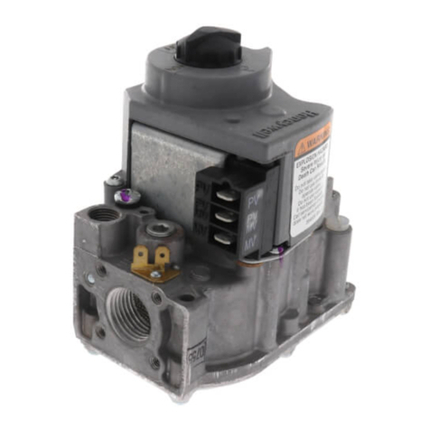
resideo VR4304 User manual

resideo

resideo VR4304 User manual

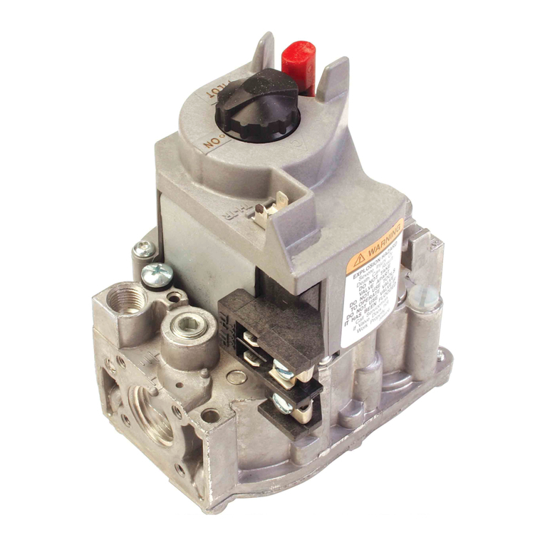
resideo VR8204A User manual

resideo

resideo VR8204A User manual

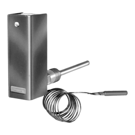
resideo Aquastat L4006 Series User manual

resideo

resideo Aquastat L4006 Series User manual

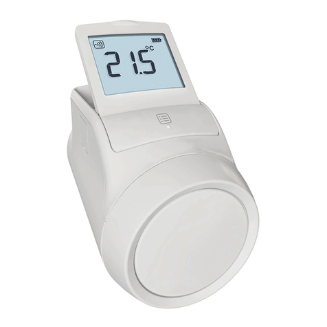
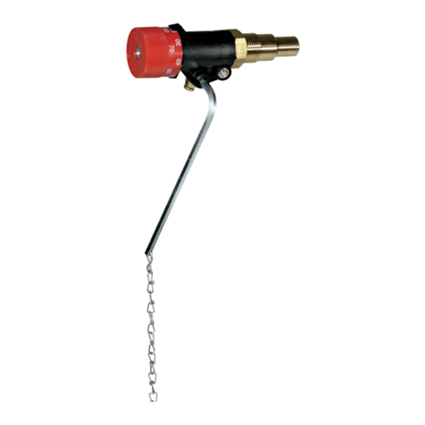
resideo Honeywell Home evohome HR92 User manual

resideo

resideo Honeywell Home evohome HR92 User manual

resideo VR4305 User manual

resideo

resideo VR4305 User manual

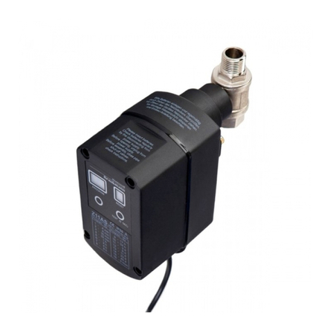
resideo Braukmann VA2400 User manual

resideo

resideo Braukmann VA2400 User manual

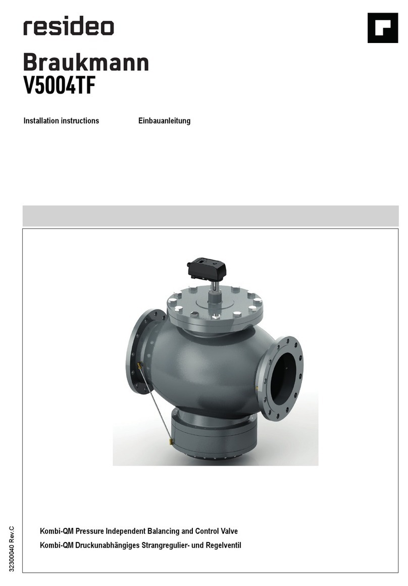
resideo Braukmann V5004TF Series User manual

resideo

resideo Braukmann V5004TF Series User manual

resideo Buoy BSV-101-WC10-LF User manual

resideo

resideo Buoy BSV-101-WC10-LF User manual

resideo VR8200A User manual

resideo

resideo VR8200A User manual

resideo Multiple Aquastat L4081A User manual

resideo

resideo Multiple Aquastat L4081A User manual

resideo CENTRA M6063 User manual

resideo

resideo CENTRA M6063 User manual

resideo Buoy BSV-101-WC10-LF User manual

resideo

resideo Buoy BSV-101-WC10-LF User manual

resideo DB7110U User manual

resideo

resideo DB7110U User manual

resideo Braukmann MV 876B1018 User manual

resideo

resideo Braukmann MV 876B1018 User manual

resideo R7284 Series User manual

resideo

resideo R7284 Series User manual

resideo Honeywell Home PRO D6 User manual

resideo

resideo Honeywell Home PRO D6 User manual

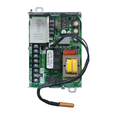
resideo Aquastat L7224 Series User manual

resideo

resideo Aquastat L7224 Series User manual

resideo VR8245 Series User manual

resideo

resideo VR8245 Series User manual

resideo Braukmann FR124 User manual

resideo

resideo Braukmann FR124 User manual

resideo Aquastat L8100A User manual

resideo

resideo Aquastat L8100A User manual

resideo VR4205 User manual

resideo

resideo VR4205 User manual

resideo VR4200 User manual

resideo

resideo VR4200 User manual

resideo VR8405 User manual

resideo

resideo VR8405 User manual

resideo VK41 Series User manual

resideo

resideo VK41 Series User manual

Popular Controllers manuals by other brands

GYS GYSPACK AIR manual

GYS

GYS GYSPACK AIR manual

Gerdes PrimuX manual

Gerdes

Gerdes PrimuX manual

YGE ProgCard III user guide

YGE

YGE ProgCard III user guide

PIETRO FIORENTINI DIXI AP Technical manual

PIETRO FIORENTINI

PIETRO FIORENTINI DIXI AP Technical manual

Elan Z-600 Quick reference guide

Elan

Elan Z-600 Quick reference guide

Trikdis GV17 installation manual

Trikdis

Trikdis GV17 installation manual

Wöhner MOTUS operating instructions

Wöhner

Wöhner MOTUS operating instructions

Weil-McLain ProtoNode FPC-N34 quick guide setup

Weil-McLain

Weil-McLain ProtoNode FPC-N34 quick guide setup

Rain Evo 1 instructions

Rain

Rain Evo 1 instructions

Hitachi H8/3637 Hardware manual

Hitachi

Hitachi H8/3637 Hardware manual

WEIHONG Lambda 4S Series Manufacturer's manual

WEIHONG

WEIHONG Lambda 4S Series Manufacturer's manual

Anaheim Automation MDCSL100-050301 user guide

Anaheim Automation

Anaheim Automation MDCSL100-050301 user guide

Controlli NR9003 Mounting instructions

Controlli

Controlli NR9003 Mounting instructions

MidNite Solar The Kid quick start guide

MidNite Solar

MidNite Solar The Kid quick start guide

Beckett HeatManager 2.5 7515 installation instructions

Beckett

Beckett HeatManager 2.5 7515 installation instructions

Deep Sea Electronics Plc 5210 operating manual

Deep Sea Electronics Plc

Deep Sea Electronics Plc 5210 operating manual

Dan Dugan Sound Design E-3 user guide

Dan Dugan Sound Design

Dan Dugan Sound Design E-3 user guide

Calsense ET2000 Programming guide

Calsense

Calsense ET2000 Programming guide

manuals.online logo
manuals.online logoBrands
  • About & Mission
  • Contact us
  • Privacy Policy
  • Terms and Conditions

Copyright 2025 Manuals.Online. All Rights Reserved.