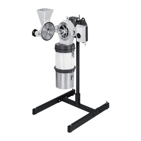
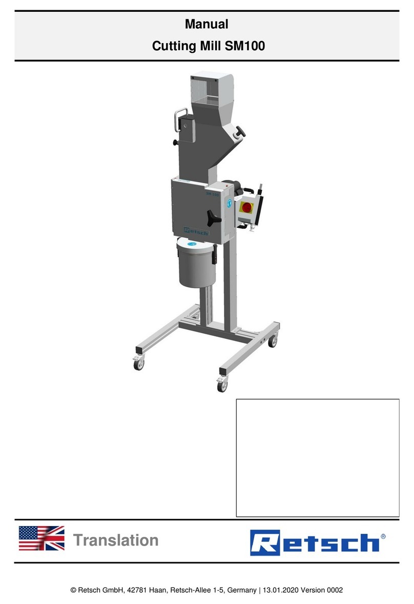
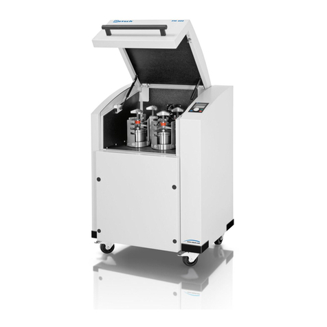
Retsch SM100 User manual

© Retsch GmbH, 42781 Haan, Retsch-Allee 1-5, Germany 13.05.2013 0000
2TManual2T
Cutting Mill SM100
2TTranslation

2
Copyright
© Copyright by
Retsch GmbH
Haan, Retsch-Allee 1-5
D-42781 Haan
Federal Republic of Germany

3
1Notes on the Operating Manual ............................................................................................................ 5
1.1 Explanations of the safety warnings.................................................................................................. 6
1.2 General safety instructions................................................................................................................ 7
1.3 Repairs............................................................................................................................................... 8
2Confirmation ........................................................................................................................................... 9
3Transport, scope of delivery, installation .......................................................................................... 10
3.1 Packaging........................................................................................................................................ 10
3.2 Transport.......................................................................................................................................... 10
3.3 Temperature fluctuations and condensed water ............................................................................. 10
3.4 Conditions for the place of installation............................................................................................. 10
3.5 Electrical connection........................................................................................................................ 11
3.6 Type plate description...................................................................................................................... 12
3.7 Removing Transport Safeguards..................................................................................................... 12
3.8 Frame assembly.............................................................................................................................. 14
3.9 Mounting the Feed Hopper.............................................................................................................. 18
3.9.1 Removing the Transport Safeguard ............................................................................................ 18
3.9.2 Mounting the Feed Hopper.......................................................................................................... 18
3.10 Installation of the machine............................................................................................................... 19
4Technical data ....................................................................................................................................... 21
4.1 Use of the machine for the intended purpose.................................................................................. 21
4.2 Emissions......................................................................................................................................... 21
4.3 Degree of protection ........................................................................................................................ 22
4.4 Motor rotation speed........................................................................................................................ 22
4.5 Receptacle volume .......................................................................................................................... 22
4.6 Rated power .................................................................................................................................... 22
4.7 Dimensions and weight.................................................................................................................... 22
4.8 Required floor space........................................................................................................................ 23
5Operating the machine ........................................................................................................................ 23
5.1 Views of the Instrument................................................................................................................... 23
5.2 Overview table of the parts of the device ........................................................................................ 26
5.3 Opening and closing of the grinding chamber................................................................................. 27
5.4 Mounting the bottom sieve............................................................................................................... 27
5.5 Replacing the rotor .......................................................................................................................... 27
5.5.1 Removing the Rotor..................................................................................................................... 28
5.5.2 Inserting the Rotor ....................................................................................................................... 28
5.6 Inserting the filter unit and collecting receptacle.............................................................................. 29
5.7 Switching On and Off....................................................................................................................... 29
5.8 Starting the grinding process........................................................................................................... 30

4
5.9 Stopping the grinding process......................................................................................................... 30
6Cleaning and service ........................................................................................................................... 30
6.1 Adjusting the cutting bars ................................................................................................................ 30
6.2 Felt gasket – servicing and replacement......................................................................................... 33
6.3 Cleaning........................................................................................................................................... 35
6.3.1 Clean the feed hopper ................................................................................................................. 36
6.3.1.1 Lift up the feed hopper safety guard.................................................................................... 36
6.3.1.2 Remove the feed hopper..................................................................................................... 37
6.3.1.3 Mount the feed hopper......................................................................................................... 37
6.3.2 Clean grinding area ..................................................................................................................... 38
6.3.3 Remove the discharge flange...................................................................................................... 38
7Disposal ................................................................................................................................................. 40
8Index ...................................................................................................................................................... 41
Appendix ............................................................................................................................... following pages

Notes on the Operating Manual
5
Pos: 1.1 /00 005 Üb ersc hriften /1. Üb erschr iften /1 Hin weise z ur Bedi enung sanlei tung @ 0\mod_1222347415287_9.doc@ 2631@ 1 @ 1
1 Notes on the Operating Manual
Pos: 1. 2/ 000 10 Bedie nungs anlei tunge n Kapit elsam mlung en/C ryoMil l/00 01 Hinw eis e z ur B e die nung sanl ei tung /M od ul H inw eis zur B edi enu ng sanl eit ung @ 0\mod_1222347341773_9.doc @ 2540@ @ 1
This operating manual is a technical guide on how to operate the device safely and
it contains all the information required for the areas specified in the table of
contents. This technical documentation is a reference and instruction manual. The
individual chapters are complete in themselves.
Familiarity (of the respective target groups defined according to area) with the
relevant chapters is a precondition for the safe and appropriate use of the device.
This operating manual does not contain any repair instructions. If faults arise or
repairs are necessary, please contact your supplier or get in touch with Retsch
GmbH directly.
Application technology information relating to samples to be processed is not
included but can be read on the Internet on the respective device’s page at
1TUwww.retsch.comU1T.
Pos: 1.3 /00 010 Bedi enu ngsa nlei tu nge n Ka pit elsa mml ung en/C r yoMill /00 01 H in weis e z ur B edie nung sa nlei tung /M odul Änder ung en @ 0\mod_1222347341241_9.doc@ 2526@ @ 1
Changes
Subject to technical changes.
Pos: 1.4 /00 010 Bedi enu ngsa nlei tu nge n Ka pit elsa mml ung en/C r yoMill /00 01 H in weis e z ur B edie nung sa nlei tung/ModulUrheberrecht@0\mod_1222347342038_9.doc@2547 @ @1
Copyright
Disclosure or reproduction of this documentation, use and disclosure of its contents
are only permitted with the express permission of Retsch GmbH.
Infringements will result in damage compensation liability.
Pos: 2.1 /00 010 Bedi enu ngsa nlei tu nge n Ka pit elsa mml ung en/------- Sei te num br uch ----------- @ 0\mod_1222344373758_0.doc@ 2386 @ @1

Notes on the Operating Manual
6
Pos: 2.2 /00 005 Übers chr ift en/1. 1 Ü ber schr if ten/ 1.1 Ü ber sc hrift en BDA/ 11 Er klärung en zu d en Sicher hei tswar nunge n @ 0\mod_1222344569771_9.doc@ 2484@ 2 @ 1
1.1 Explanations of the safety warnings
Pos: 2. 3/ 000 03 Stand ard Ka pitel/ Gener al Modul Warn hin weise Er klärung neu @ 0\ mod_1234858329746_9.doc@ 6190@ @ 1
In this Operating Manual we give you the following safety warnings
Serious injury may result from failing to heed these safety warnings. We give you
the following warnings and corresponding content.
WARNING
Type of danger / personal injury
Source of danger
– Possible consequences if the dangers are not observed.
• Instructions on how the dangers are to be avoided.
We also use the following signal word box in the text or in the instructions on action
to be taken:
WARNING
Moderate or mild injury may result from failing to heed these safety warnings.
We give you the following warnings and corresponding content.
CAUTIO
N
Type of danger / personal injury
Source of danger
– Possible consequences if the dangers are not observed.
• Instructions on how the dangers are to be avoided.
We also use the following signal word box in the text or in the instructions on action
to be taken:
CAUTION
In the event of possible property damage we inform you with the word
“Instructions” and the corresponding content.
NOTICE
Nature of the property damage
Source of property damage
– Possible consequences if the instructions are not observed.
• Instructions on how the dangers are to be avoided.
We also use the following signal word in the text or in the instructions on action to
be taken:
NOTICE
Pos: 2.4 /00 010 Bedi enu ngsa nlei tu nge n Ka pit elsa mml ung en/------- Sei te num br uch ----------- @ 0\mod_1222344373758_0.doc@ 2386 @ @1

Notes on the Operating Manual
7
Pos: 2. 5/ 000 05 Übersc hrif ten/1. 1Ü ber schrif ten/ 1.1 Übers chri ften BD A/11 G enerel le Sic herhei tshi nweise @ 0\mod_1222344568974_9.doc@ 2463 @ @ 1
1.2 General safety instructions
Pos: 2. 6/ 000 04 Warnhi nweis e/V 0002 VOR SICH T Bedie nungs anlei tung l esen @ 2\mod_1263894982815_9.doc @ 18630@ @ 1
CAUTION
Read the Operating Manual
Non-observance of these operating instructions
– The non-observance of these operating instructions can
result in personal injuries.
• Read the operating manual before using the device.
• We use the adjacent symbol to draw attention to the
necessity of knowing the contents of this operating
manual.
Pos: 2. 7/ 000 03 Stand ard Ka pitel/ Gener al Modul Zielg rupp e und Sic herhei t @ 0\mod_1228722955300_9.doc@4100 @ @1
Target group : All persons concerned with the machine in any form
This machine is a modern, high performance product from Retsch GmbH and
complies with the state of the art. Operational safety is given if the machine is
handled for the intended purpose and attention is given to this technical
documentation.
Pos: 2. 8/ 000 03 Stand ard Ka pitel/ Gener al Modul Sic herhei tshin weise @ 0\mod_1228722954800_9.doc @ 408 6 @ @ 1
You, as the owner/managing operator of the machine, must ensure that the people
entrusted with working on the machine:
• have noted and understood all the regulations regarding safety,
• are familiar before starting work with all the operating instructions and
specifications for the target group relevant for them,
• have easy access always to the technical documentation for this machine,
• and that new personnel before starting work on the machine are familiarised
with the safe handling of the machine and its use for its intended purpose,
either by verbal instructions from a competent person and/or by means of
this technical documentation.
Improper operation can result in personal injuries and material damage. You are
responsible for your own safety and that of your employees.
Make sure that no unauthorised person has access to the machine.
Pos: 2.9 /00 0 04 Warnhi nweis e/ V 0015 VORS ICHT + HI NWE IS Sach- undPersonenschäden @ 1\mod_1236238456676_9.doc@ 7642 @ @1
CAUTION
Changes to the machine
– Changes to the machine may lead to personal injury.
• Do not make any change to the machine and use spare parts and
accessories that have been approved by Retsch exclusively.
NOTICE
Changes to the machine
– The conformity declared by Retsch with the European Directives will lose
its validity.
– You lose all warranty claims.
• Do not make any change to the machine and use spare parts and
accessories that have been approved by Retsch exclusively.
Pos: 2. 10 /00 010 Bedi enung sanlei tung en K api tels am mlu nge n/------- Seit enu mbruc h ----------- @ 0\mod_1222344373758_0.doc @ 2386@ @ 1

Notes on the Operating Manual
8
Pos: 2. 11 /00 005 Über schrif ten/ 1.1 Über schri ften/ 1.1 Üb erschr iften BD A/11 R epar ature n @ 0\mod_1223624336511_9.doc@ 2978@ @ 1
Reper atur en
1.3 Repairs
Pos: 2. 12 /00 003 Stan dard K apitel/ Gen eral Mod ul Repar atur en @ 0\mod_1228722954535_9.doc@4079 @ @1
This operating manual does not contain any repair instructions. For your own
safety, repairs may only be carried out by Retsch GmbH or an authorized
representative or by Retsch service engineers.
In that case please inform:
The Retsch representative in your country
Your supplier
Retsch GmbH directly
Your Service Address:
Pos: 3.1 /00 020 BDA Softw are/ 200 05 PM GC Kapi tel sam ml ung/- - - - Seit enu mbr uch - - - - @ 0\mod_1208857688413_0.doc@ 337@ @ 1

Confirmation
9
Pos: 3. 2/ 001 0 BDA Soft ware/ Übers chrif ten/1. Ü bersc hrift en/1 B estäti gung (F ormul ar für d en Betr eiber) @ 0\mod_1208870841095_9.doc@ 430@ 1 @ 1
Bestä tigung
2 Confirmation
Pos: 3. 3/ 000 03 Stand ard Ka pitel/ Gener al Modul Best ätigu ng @ 0\mod_1228722962707_9.doc@ 4114@ @ 1
This operating manual contains essential instructions for operating and maintaining
the device which must be strictly observed. It is essential that they be read by the
operator and by the qualified staff responsible for the device before the device is
commissioned. This operating manual must be available and accessible at the
place of use at all times.
The user of the device herewith confirms to the managing operator (owner) that
(s)he has received sufficient instructions about the operation and maintenance of
the system. The user has received the operating manual, has read and taken note
of its contents and consequently has all the information required for safe operation
and is sufficiently familiar with the device.
As the owner/managing operator you should for your own protection have your
employees confirm that they have received the instructions about the operation of
the machine.
I have read and taken note of the contents of all chapters in this operating
manual as well as all safety instructions and warnings.
User
Surname, first name (block letters)
Position in the company
Signature
Service technician or operator
Surname, first name (block letters)
Position in the company
Place, date and signature
Pos: 4/ 000 10 B edi enu ngsa nlei tu nge n Ka pit elsa mml ung en/------- Seitenumbruch-----------@ 0\mod_1222344373 758_ 0.doc @ 238 6 @ @ 1

Transport, scope of delivery, installation
10
Pos: 5. 1/ 00005 Üb ersc hriften /1. Über schri ften/1 V erpac kung, Tr anspor t und Auf stell ung @ 0\mod_1226494451893_9.doc@ 3380@ 1 @ 1
3 Transport, scope of delivery, installation
Pos: 5. 2/ 000 05 Übersc hrif ten/1. 1Ü ber schrif ten/ 1.1 Übers chri ften BD A/11 Ver pac kung @ 0\mod_1226495088973_9.doc@3392 @ 2 @ 1
3.1 Packaging
Pos: 5. 3/ 000 03 Stand ard Ka pitel/ Gener al Modul Verp ackung @ 0\mod_1228984618355_9.doc@ 4892 @ @1
The packaging has been adapted to the mode of transport. It complies with the
generally applicable packaging guidelines.
Pos: 5.4 /00 004 Warnhi nweise/H 0001 HINW EIS Aufbe wahrung der Ver packung @ 0\mod_1228918881595_9.doc@ 4753 @ @1
NOTICE
Storage of packaging
– In the event of a complaint or return, your warranty claims may be
endangered if the packaging is inadequate or the machine has not been
secured correctly.
• Please keep the packaging for the duration of the warranty period.
Pos: 5.5 /00 005 Übers chr ift en/1. 1 Ü ber schr if ten/ 1.1 Ü ber sc hrift e n BDA/ 1 1 Tr ansp ort @0 \mod_1226495164391_9.doc @ 3398@ 2@ 1
3.2 Transport
Pos: 5.6 /00 0 04 Warnhi nweis e/H 0 017 H IN WEI S T r ansp ort @ 0\mod_1228918883019_9.doc @ 4802@ @ 1
NOTICE
Transport
– Mechanical or electronic components may be damaged.
• The machine may not be knocked, shaken or thrown during
transport.
Pos: 5.7 /00 005 Übers chr ift en/1. 1 Ü ber schr if ten/ 1.1 Ü ber sc hrift e n BDA/ 1 1 Te mper atur sc hwan ku nge n @ 0 \mod_1226495190738_9.doc@ 3404@ 2 @ 1
3.3 Temperature fluctuations and condensed water
Pos: 5.8 /00 004 War nhin weis e/H 001 6 H INWE IS T emp era turs ch wan kung en @ 0\mod_1233564121287_9.doc@ 5570@ @ 1
NOTICE
Temperature fluctuations
The machine may be subject to strong temperature fluctuations during transport
(e.g. aircraft transport)
– The resultant condensed water may damage electronic components.
• Protect the machine from condensed water.
Pos: 5.9 /00 005 Übers chr ift en/1. 1 Ü ber schr if ten/ 1.1 Ü ber sc hrift e n BDA/ 1 1 Be ding ung en f ür d en A ufs tell or t @ 0\mod_1226497029322_9.doc@ 3428@ 2 @ 1
3.4 Conditions for the place of installation
Pos: 5. 10 /00 003 Stan dard K apitel/ Gen eral M odul U mgeb ungst emper atur 5 °C - 40°C @ 0\mod_1228918538881_9.doc@ 4745@ @ 1
Pos: 5. 11 /00 004 Warn hinw eise/H 0021 HIN WEIS U mge bungst emper atur 5°C bis 4 0°C @ 0\mod_1228918883441_9.doc@ 4816 @ @1
NOTICE
Ambient temperature
– Electronic and mechanical components may be damaged and the
performance data alter to an unknown extent.
• Do not exceed or fall below the permitted temperature range of the
machine (5°C to 40°C / ambient temperature).
Pos: 5. 12 /00 003 Stan dard K apitel/ Gen eral Mod ul Luftfeuchtigkeit@ 0\mod_1228918538693_9.doc@ 4738@ @ 1
Atmospheric humidity:
Maximum relative humidity 80% at temperatures up to 31°C, decreasing linearly up
to 50% relative humidity at 40°C
Pos: 5. 13 /00 004 Warn hinw eise/H 0011 HIN WEIS L uftf euchtig kei t @ 0\mod_1228918882628_9.doc@ 4788@ @ 1

Transport, scope of delivery, installation
11
NOTICE
Atmospheric humidity
– Electronic and mechanical components may be damaged and the
performance data alter to an unknown extent.
• Do not exceed the admissible range for atmospheric humidity.
Pos: 5.14 /0 000 5 Ü ber schri fte n/ 1.1 Ü bers chr ift en/ 1. 1 Über sc hrif ten BDA/ 11 El ektr isc her Ansc hlus s @ 0\mod_1226565067445_9.doc@ 3500@ 2 @ 1
3.5 Electrical connection
Pos: 5. 15 /0000 3 Stan dard K apitel/ Gen eral Mod ul Elek trisch er Ans chluss @ 0\mod_1228918538521_9.doc@ 4731 @ @ 1
WARNING
When connecting the power cable to the mains supply, use an external fusethat
complies with the regulations applicable to the place of installation .
• Please check the type plate for details on the necessary voltage and
frequency for the device.
• Make sure the levels agree with the existing mains power supply.
• Use the supplied connection cable to connect the device to the mains power
supply.
Pos: 5. 16 /00 004 Warn hinw eise/H 0008 HIN WEIS E lektr isch er Ansc hluss @ 0 \mod_1228918882424_9.doc@4781 @ @1
NOTICE
Electrical connection
– Mechanical or electronic components may be damaged.
• Please observe the information on the type plate.
Pos: 5. 17 /00 010 Bedi enung sanlei tung en Kapi telsa mmlu ngen/------- Sei te num bruc h ----------- @ 0\mod_1222344373758_0.doc@ 2386@ @ 1

Transport, scope of delivery, installation
12
Pos: 5. 18.1 /0 0005 Üb erschr ifte n/1.1 Ü bersc hrifte n/1.1 Ü bersc hrift en BDA/ 11 Type nschi ld Besc hreib ung @ 3\mod_1280933953941_9.doc@ 22302 @ 2 @ 1
3.6 Type plate description
Pos: 5. 18.2 /0 0003 St andar d Kapit el/Ge neral M odul Ty pensc hil d @ 3 \mod_1280931092443_9.doc@ 22278 @ @ 1
Fig. 1: Type plate lettering
1 Device designation
2 Year of production
3 Part number
4 Serial number
5 Manufacturer’s address
6 CE marking
7 Disposal label
8 Bar code
9 Power version
10 Mains frequency
11 Capacity
12 Amperage
13 Number of fuses
14 Fuse type and fuse strength
In the case of questions please provide the device designation (1) or the part
number (3) and the serial number (4) of the device.
Pos: 5. 19 /00 005 Über schrif ten/ 1.1 Über schri ften/ 1.1 Üb erschr iften BD A/11 T rans porthi lfe en tfern en @ 0\mod_1229076673566_9.doc@ 5020 @ 2 @ 1
3.7 Removing Transport Safeguards
Pos: 5. 20 /00 010 Bedi enung sanlei tung en Kapi telsa mmlu ngen/ SM10 0/0010 SM 100 Tr ansp ort, Li eferu mfang u nd Aufst ellen /1010 SM 100 M odul Tr anspor thil fe entfer nen @ 3\mod_1284973889130_9.doc@ 23629@ @1
1
2
3
4
5
6
7
8
9
10
11
12
14
13

Transport, scope of delivery, installation
13
Fig. 2: Removing the transport aid
Only use the transport aid (TH) when lifting the device. The device weighs approx.
73 kg. Select secure lifting equipment that is approved for this weight.
Keep the eyebolt (TH) for transportation at a later date.
The eyebolt must be removed before assembling the hopper.
Pos: 5. 21 /00 010 Bedi enung sanlei tung en Kapi telsa mmlu ngen/------- Sei te num bruc h ----------- @ 0\mod_1222344373758_0.doc@ 2386@ @ 1
TH

Transport, scope of delivery, installation
14
Pos: 5.22 /0 000 5 Ü ber schri fte n/ 1.1 Ü bers chr ift en/ 1. 1 Über sc hrif ten BDA/ 11 G est ell M ont age @ 3\mod_1292917288312_9.doc@ 24070@ @ 1
3.8 Frame assembly
Pos: 5. 23 /00 010 Bedi enung sanlei tung en Kapi telsa mmlu ngen/ SM10 0/0010 SM 100 Tr ansp ort, Li eferu mfang u nd Aufst ellen /1020 SM 100 M odul Ge stell monti eren @ 3\mod_1292496265450_9.doc@ 24060@ @1
Fig. 3: Components of the stand
The components come pre-assembled to simplify assembly of the frame.
Fig. 4: Assembling the crossbar
• Where necessary slightly loosen the four screws (TS) on the crossbar (TR).
• Slide the crossbar into the lateral guides of the left and right roller track (RS).
TR
RS
TS
SQ
RS
TR
RS

Transport, scope of delivery, installation
15
Fig. 5: Fastening the crossbar angle bracket
NB
Ensure that the crossbar (TR) is aligned flush with the pre-assembled angle
section (WS).
Tighten the screw on the left and right of the angle section (SW).
Fig. 6: Screwing the crossbar tight
• Tighten the four Allen screws.
TR
WS
WS
SW

Transport, scope of delivery, installation
16
Fig. 7: Mounting the side protective caps
• Place the four black plastic caps on the openings.
Fig. 8: Mounting the front protective caps
• Place the two caps on the ends of the roller track.
SQ

Transport, scope of delivery, installation
17
Fig. 9: Placing the crossbar on the stand
• Place the stand (SQ) on the crossbar.
Fig. 10: Points for securing the stand
Fig. 11: Screwing the stand onto the crossbar
• Screw the stand (SQ) onto the crossbar.
Fig. 12: Assembling the SM 100
• Then place the SM100 on the base frame.

Transport, scope of delivery, installation
18
• Using the 4 screws, screw the SM100 housing tightly onto the base frame.
Pos: 5.24 /0 000 5 Ü ber schri fte n/ 1.1 Ü bers chr ift en/ 1. 1 Über sc hrif ten BDA/ 11 Mont age des Ei nfüllt ric hters @ 2\mod_1258709491283_9.doc@ 17540@ @ 1
3.9 Mounting the Feed Hopper
Pos: 5.25 /0 0 004 Warnhi nw eis e/ W00 04 WARNUN G sc h nell r ot ier end e M ess er @ 3\mod_1280230540628_9.doc@ 22034@ @ 1
WARNING
1.
W0004
Risk of injury to skin and hands
Fast rotating cutting blade
– There is a risk of injuring hands, fingers and skin.
• Never operate the device without a feed hopper.
Pos: 5. 26 /00 004 Warn hinw eise/H 0019 HIN WEIS T rans ports icher ung SM 300 @ 0\mod_1228918883206_9.doc@ 4809@ @ 1
NOTICE
Transport safeguard
– Components may be damaged.
• Operate the machine only without the transport safeguard or
transport the machine only with transport safeguard.
Pos: 5.27 /0 000 5 Ü ber schri fte n/ 1.1. 1 Ü bersc hri fte n/ 111 Tr ans por tsi cher ung entf ern en @ 2\mod_1258709630300_9.doc@ 17547@ @ 1
3.9.1 Removing the Transport Safeguard
Pos: 5. 28 /00 010 Bedi enung sanlei tung en Kapi telsa mmlu ngen/ SM10 0/0010 SM 100 Tr ansp ort, Li eferu mfang u nd Aufst ellen /1015 SM 100 M odul Tr anspor tsic heru ng entfer nen @ 3\mod_1284973890770_9.doc@ 23638@ @1
Fig. 13: Removing the transport lock
• Remove the transport aid (TH).
• Turn the door lock grip (TV) until the door can be opened.
• Open the grinding area door (T).
• Remove the two safety screws (S).
NB
Retain the transport lock (TS) for transportation at a later date.
Pos: 5.29 /0 000 5 Ü ber schri fte n/ 1.1. 1 Ü bersc hri fte n/ 111 Ei nfül ltr ic hter monti ere n @ 2 \mod_1258709690814_9.doc@ 17554@ @ 1
3.9.2 Mounting the Feed Hopper
Pos: 5. 30 /00 010 Bedi enung sanlei tung en Kapi telsa mmlu ngen/ SM10 0/0010 SM 100 Tr ansp ort, Li eferu mfang u nd Aufst ellen /1005 SM 100 M odul Einfül ltr ic ht er montier en @ 3\mod_1284973885973_9.doc@ 23620@ @ 1
TH
TS
S
T
TV

Transport, scope of delivery, installation
19
Fig. 3: Mounting the feed hopper
• Open the grinding area door (T).
• Pull the plunger (B) so it engages in the uppermost position.
• Place the feed hopper (R) on the device (see diagram)
CAUTION
It is possible for the feed hopper (R) to fall from the device as long
as it is not secured by the three socket screws.
• Unlock the locking pins (D) of the plunger (B).
• Slide the plunger down.
• Screw in the three supplied socket screws (S).
• Initially only tighten the screws loosely.
• Close the grinding area door (T).
• Twist the rotary grip of the grinding area door.
• Align the feed hopper so that the plunger can be easily moved up and down
without tilting.
• Screw the three socket screws tight (10Nm).
• Check again that the plunger can be easily moved up and down without
tilting.
NB
The grinding area door and the grip of the door lock are somewhat stiff when new.
Pos: 5. 31 /00 005 Über schrif ten/ 1.1 Über schri ften/ 1.1 Üb erschr iften BD A/11 A ufstel len d es Gerät es @ 0\mod_1226498849756_9.doc@ 3464 @ 2 @ 1
3.10 Installation of the machine
Pos: 5. 32 /00 003 Stan dard K apitel/ Gen eral Mod ul Aufst ellu ngshöh e @ 0\mod_1228918538349_9.doc@ 4724 @ @1
Installation height: maximum 2000 m above sea level
Pos: 5. 33 /00 004 Warn hinw eise/H 0004 HIN WEIS B ode n Aufst ellen Vi bratio nen B oden @ 0\mod_1228918882236_9.doc @4774 @ @ 1
S
T
B
R
D
S

Transport, scope of delivery, installation
20
NOTE
Installation
– Depending on the operating status of the mill, there may be slight
vibrations.
• Place the mill on an even, flat and balanced supporting surface only.
The supporting surface must be stable and must not vibrate.
Pos: 5. 34 /00 004 Warn hinw eise/H 0002 HIN WEIS A ufstel lung Z ugang G erät estec kdos e @ 0\mod_1233836960983_9.doc@ 5820@ @1
NOTICE
Installation of the machine
– It must be possible to disconnet the machine from the mains at any time.
• Install the machine such that the connection for the mains cable is
easily accessible.
Pos: 6.1 /00 010 Bedi enu ngsa nlei tu nge n Ka pit elsa mml ung en/------- Sei te num br uch ----------- @ 0\mod_1222344373758_0.doc@ 2386 @ @1
Other manuals for SM100
2
Table of contents
Other Retsch Power Tools manuals

Retsch
Retsch RS200 User manual

Retsch
Retsch PP 35 User manual

Retsch
Retsch SR 300 User manual

Retsch
Retsch SR 200 User manual

Retsch
Retsch SM100 User manual

Retsch
Retsch RM200 User manual

Retsch
Retsch PM400 User manual

Retsch
Retsch SM 400 User manual

Retsch
Retsch BB 600 User manual

Retsch
Retsch PP 25 User manual
Popular Power Tools manuals by other brands

Hilti
Hilti TE 30 manual

Fein
Fein MM 700 MAX Translation of the original instructions

Westfalia
Westfalia 19 38 47 Original instruction manual

Black & Decker
Black & Decker SPITFIRE SP5500JS instruction manual

MULTIPRESS
MULTIPRESS M5P Series Operating instructions and service manual

jbc
jbc AP250 instruction manual