CONVESSI GRAND SWING-ARM SCONCE
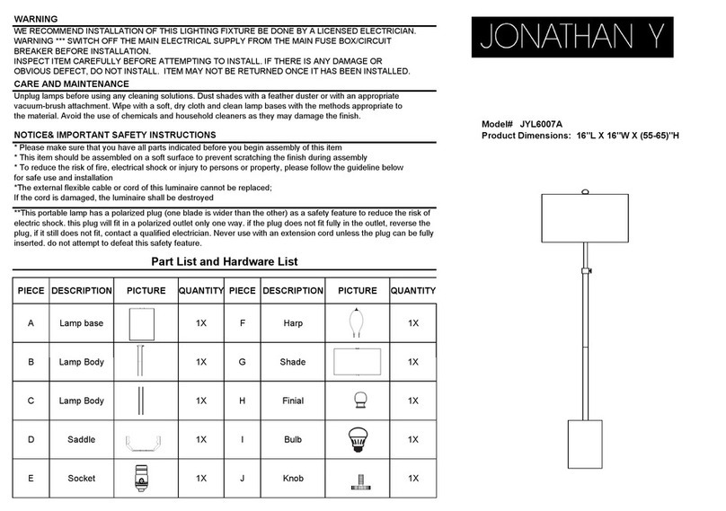
IMPORTANT SAFETY INSTRUCTIONS
INSTALLATION BY A LICENSED ELECTRICIAN IS STRONGLY
RECOMMENDED.
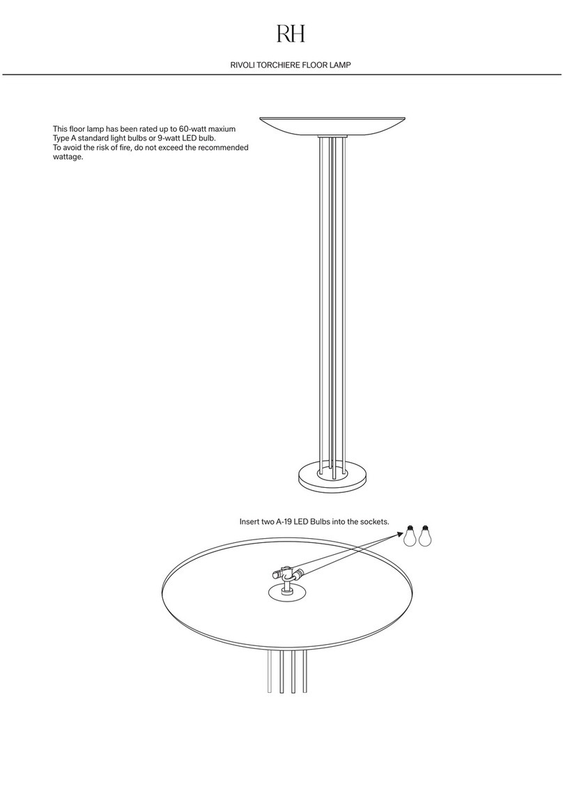
This xture has been rated for one (1) 60-Watt maximum Type B
lightbulb (not included), one (1) 13-Watt compact uorescent bulb
(not included), or one (1) 5.5-Watt SBLED lightbulb (included). To
avoid the risk of re, do not exceed the recommended wattage.
WARNINGS
All wires are connected. When unpacking, be careful not to pull
wires, as a bad connection may result. Do not connect electricity
until your fixture is fully assembled. To reduce the risk of fire,
electrical shock, or personal injury, always turn off fixture and allow it
to cool prior to replacing the lightbulb. Do not touch or look directly
at the bulb when fixture is illuminated. Keep flammable materials
away from lit bulb.
WARNING: This product can expose you to lead, which is
known to the State of California to cause cancer and birth defects or
other reproductive harm. For more information, go to
www.P65Warnings.ca.gov.
THIS PRODUCT IS NOT A TOY AND HAS NO
PLAY VALUE.
WARNING: STRANGULATION HAZARD
Keep cord at least 3 feet away from cribs, bassinets, and toddler
beds. Keep out of reach of children under 3 years of age.
ASSEMBLY & INSTALLATION
SHUT OFF THE MAIN ELECTRICAL SUPPLY FROM THE FUSE
BOX OR CIRCUIT BREAKER PANEL.
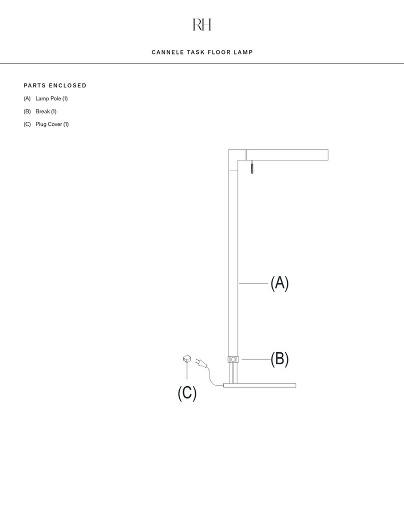
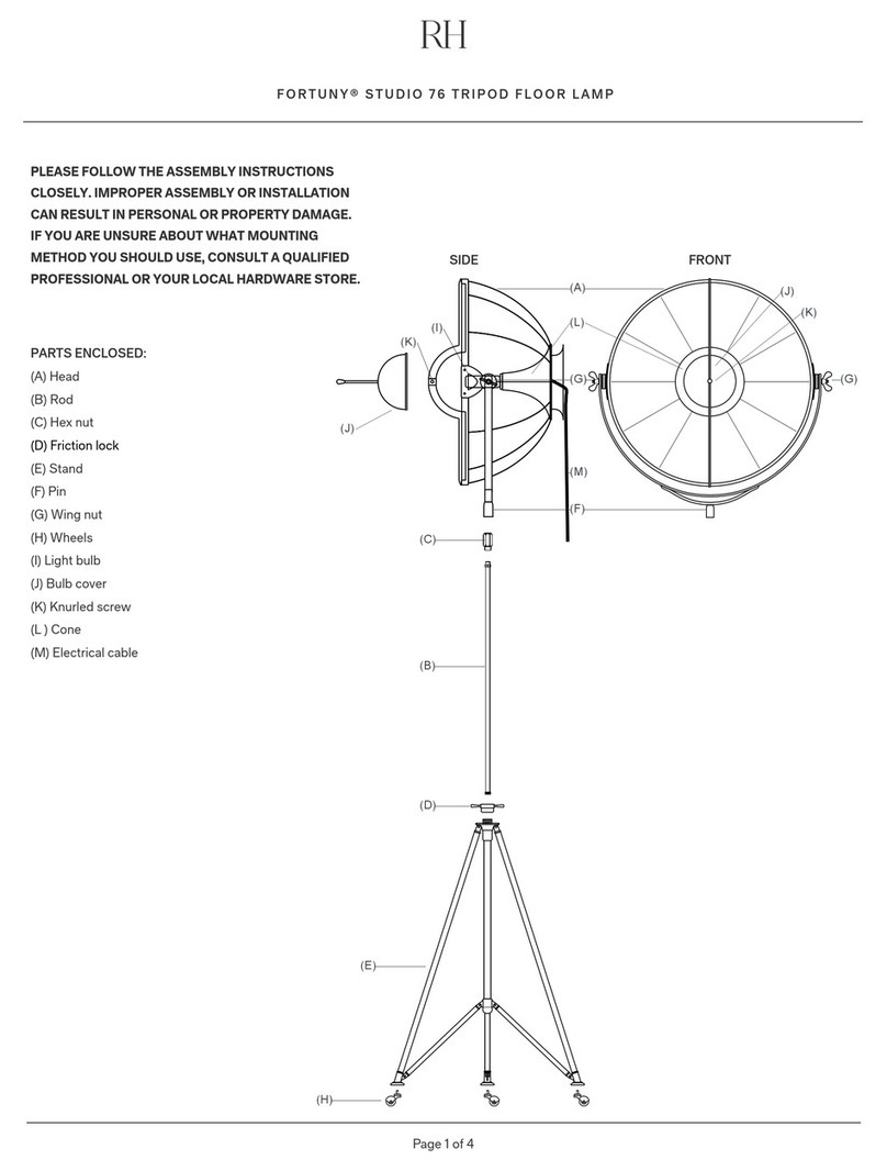
PORTABLE ASSEMBLY: See Fig. 1
1. Carefully remove all parts from the box and remove all plastic
coverings.
2. Measure the center distance of both hanging keyholes on the
back side of Lamp Base (C). Make pencil marks on the wall for
the holes with the same distance at the desired height; make
sure the holes are level with each other.
3. Drill a small hole on each pencil mark on the wall. Each hole
should be large enough to accommodate Metal Anchors (A).
ASSEMBLY & INSTALLATION CONT.
Push Metal Anchors (A) into the holes in the wall.
4. Insert Mounting Screws (B) into Metal Anchors (A). Make sure
both screw heads with 1/8" threads are visible.
5. Hook Lamp Base (C) onto both heads of Mounting Screws (B).
6. Insert Bulb (E) into the socket.
HARDWIRE ASSEMBLY: See Fig. 2
1. Carefully remove all parts from the box and remove all plastic
coverings.
2. Guide wiring from the wall outlet box through the center hole
in Mounting Plate (F). Ax Mounting Plate (F) to the wall outlet
box with Mounting Screws (G).
3. Cut the wire 12 inches away from Fixture Base (C).
4. Insert the Direct Wire Plug (I) to the threaded hole vacated by
the cord.
5. Ax the xture ground wire to the house ground wire (usually
bare copper) from the wall outlet box with a wire nut. IT IS
IMPERATIVE THAT THE OUTLET BOX IN YOUR HOME BE
PROPERLY GROUNDED.
6. Connect both neutral wires (white) from light xture to the
neutral outlet wire (usually white insulation) with a plastic wire
connector and wrap the connection with electrical tape.
7. Connect the hot wires (black) from light xture to the hot
outlet box wire (usually black insulation) with a plastic wire
connector and wrap the connection with electrical tape. DO
NOT REVERSE THE HOT AND NEUTRAL CONNECTIONS OR
SAFETY WILL BE COMPROMISED.
8. Carefully tuck the wires back into the outlet box.
9. Attach Fixture Base (C) to the axed Mounting Plate (F) and
secure with Base Screws (H).
10. Insert Bulb (E) into the socket.
11. Assembly is complete.
TO ADJUST:
1. Turn Adjustment Key (D) in a counterclockwise direction to
loosen, then adjust the lamp shade to desired position.
2. Turn Adjustment Key (D) in a clockwise direction to tighten.
CARE INSTRUCTIONS
Do not use polishes or cleaners on the fixture. Wipe clean with a
soft, dry cloth.
