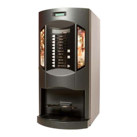
N&W Global Vending Canto LB 3600 Owner's manual

INSTALLATION, OPERATION, MAINTENANCE
EN English
Do c . No. H 83127 00
Ed i t i o n 1 11 - 2009
LB 3600 Canto
230 V


Italiano ¿º¿¹¾¿·È·¹¾»Â·Ã·¹¹¾¿Ä·Ƒº»É¹È¿ÊʷĻ·ʷȽ¾»ÊÊ·º¿¿º»ÄÊ¿Ű¹·Ð¿ÅÄ»Ƒò
¹ÅļÅÈû·Â»º¿ÉÆÅɿпÅĿ»½¿É·ʿ̻º»Â»¿È»Êʿ̻ËÈÅÆ»»»Â»Ä¹·Ê»·Â·ÊÅ»É˹-
¹»Éɿ̻Ãź¿Ű¹¾»»º¿ÄÊ»½È·Ð¿ÅÄ¿Ɣ
English ¾»Ã·¹¾¿Ä»º»É¹È¿¸»º¿Äʾ»¿º»ÄÊ¿Ű¹·Ê¿ÅÄÆÂ·Ê»¹ÅļÅÈÃÉÊÅʾ»Â»½¿É·-
ʿ̻º¿È»¹Ê¿ÅÄÉżʾ»ËÈÅÆ»·Äº¿È»¹Ê¿Ì»É¿ÉÊ»º·ÊÉ¿º»·Äº¼ËÈʾ»È·Ã»ÄºÃ»ÄÊɷĺ
¿ÄÊ»½È·Ê¿ÅÄÉ
English ¾»¾·ÈÃÅĿɻºÉʷĺ·ÈºÉÅÈÊ»¹¾Ä¿¹·ÂÉÆ»¹¿Ű¹·Ê¿ÅÄÉƺº»É¿½Ä·Ê¿ÅÄÉƻ;¿¹¾
¹ÅÃÆÂÏͿʾ½Åź»Ä½¿Ä»»È¿Ä½ÆÈ·¹Ê¿¹»¿ÄÉ·¼»ÊÏ÷ÊÊ»ÈɿļÅȹ»Í¿Ê¾¿Äʾ»¾·Ì»
¸»»Ä·ÆÆÂ¿»º·È»Ɠ
Français ·Ã·¹¾¿Ä»ºó¹È¿Ê»ÉËÈ·ÆÂ·ÇË»ÊÊ»ºƠ¿º»ÄÊ¿Ű¹·Ê¿ÅÄ»ÉʹÅļÅÈû·ËÎ
º¿ÉÆÅɿʿÅÄÉÂó½·Â»Éº»Éº¿È»¹Ê¿Ì»É»ËÈÅÆó»ÄÄ»ÉóÄÅĹó»É¹¿Ɩ¹ÅÄÊÈ»»ÊÃź¿Ű¹·Ê¿ÅÄÉ
»Ê¿ÄÊó½È·Ê¿ÅÄÉÉ˹¹»Éɿ̻É
Español »º»¹Â·È·Ç˻·ÃÒÇ˿ķƑº»É¹È¿ÆÊ·»Ä·»Ê¿Ç˻ʷº»¿º»ÄÊ¿Ű¹·¹¿ĤÄƑ¹ËÃ-
ÆÂ»¹ÅÄ·ɺ¿ÉÆÅÉ¿¹¿ÅĻɻ½¿É·ʿ̷ɺ»Â·É¿È»¹ÊÈ¿¹»ÉËÈÅÆ»·É¿ÉÊ·º·É·Â÷Ƚ»Ä
Ϻ»ÉËÉÉ˹»É¿Ì·ÉÃź¿Ű¹·¹¿ÅĻɻ¿ÄÊ»½È·¹¿ÅÄ»É
Português »¹Â·È·ƖÉ»ÇË»·ÃÒÇ˿ķƑº»É¹È¿Ê·Ä·ÆÂ·¹·º»¿º»ÄÊ¿Ű¹·îÙÅ»ÉÊÒ¹ÅÄ-
¼ÅÈû·Éº¿ÉÆÅÉ¿îī»É»½¿É·ʿ̷ɺ·É¿È»ÊȿлÉËÈÅÆó¿·É»Â»Ä¹·º·É·ÇË¿·Å·ºÅ»
É˹»Éɿ̷ÉÃź¿Ű¹·îī»É»¿ÄÊ»½È·îī»É
Deutsch ·É·Ë¼º»ÃÏÆ»Äɹ¾¿Âº¸»É¹¾È¿»¸»Ä»»ÈÚÊ»ÄÊÉÆÈ¿¹¾Êº»ÄÈ»¹¾Êɷ˼½»-
¼Ŏ¾ÈʻĽ»É»Êп¹¾»ÄËÈÅÆÚ¿É¹¾»Ä¿¹¾Ê¿Ŀ»ÄƑÉÅÍ¿»·Äɹ¾Â¿»Ņ»Äº»Ä'ĺ»ÈËĽ»Ä
ËĺȽÚÄÐËĽ»Ä
Nederlands »Ã·¹¾¿Ä»¸»É¹¾È»Ì»ÄÅÆ¾»Ê¿º»ÄÊ¿Ű¹·Ê¿»ÆÂ··ÊÀ»¿É¹ÅļÅÈú»
Í»Êɸ»Æ·Â¿Ä½»Ä̷ĺ»ËÈÅÆ»É»¿¹¾Ê¿ÀĻĺ¿»¾¿»ÈÄ··ÉÊÌ»ÈûºÍÅȺ»Ä»Ä·ʻȻ
·Ã»Äº»Ã»ÄʻĻķ·ÄÌË¿Ľ»Ä
Italiano »ÄÅÈû·ÈÃÅÄ¿ÐзʻÅÂ»ÉÆ»¹¿Ű¹¾»Ê»¹Ä¿¹¾»ƺº»É¿½Ä·Ð¿ÅÄ¿ƻ¹¾»ÉÅÄÅ
ÉÊ·Ê»·ÆÆÂ¿¹·Ê»¿Ä·¹¹ÅȺŹÅÄ»Ȼ½Å»º»Â·¸ËÅÄ··ÈÊ»¿Ä÷ʻȿ·º¿É¿¹ËÈ»Ðз¿Ä
Ì¿½ÅȻĻ·ÉÅÄÅƓ
Français »ÉÄÅÈûɾ·ÈÃÅÄ¿Éó»ÉÅË»ÉÉÆó¹¿Ű¹·Ê¿ÅÄÉÊ»¹¾Ä¿ÇË»ÉƺºóÉ¿½Ä·Ê¿ÅÄÉƻ
ÇË¿ÅÄÊóÊó·ÆÆÂ¿ÇËó»É¹ÅļÅÈÃóûÄÊ·ËÎÈò½Â»Éº»Â·¸ÅÄÄ»ÆÈ·Ê¿ÇË»»Ä÷ʿòÈ»º»
Éó¹ËÈ¿Êó»ÄÌ¿½Ë»ËȺ·ÄÉÂƠÉÅÄÊƓ
Deutsch ¿»¾·ÈÃÅĿɿ»ÈÊ»Äʷĺ·ÈºÉź»ÈÊ»¹¾Ä¿É¹¾»ÄƻпŰÁ·Ê¿ÅÄ»Äƺ»ÉÊ¿Ã-
ÃËĽ»ÄƻƑº¿»º»Ä»½»Âĺ»ÈËÄÉʾ¿ÄÉ¿¹¾Ê¿¹¾º»Ä¿Äº»È½»Âʻĺ»Ä¿¹¾»È¾»¿ÊÉ-
ÄÅÈûĻÄÊÉÆÈ»¹¾»ÄƑɿĺƓ
Español ·ÉÄÅÈ÷ɷÈÃÅĿзº·ÉÅÂ·É»ÉÆ»¹¿Ű¹·¹¿ÅÄ»ÉÊó¹Ä¿¹·Éƺº»É¿½Ä·¹¿ÅÄ»Éƻ
ÇË»¾·ÄÉ¿ºÅ·ÆÂ¿¹·º·Éº»·¹Ë»ÈºÅ¹ÅÄ·ÉÈ»½Â·Éº»Â·¸Ë»Ä·ÆÈҹʿ¹·»Ä÷ʻȿ·º»
É»½ËÈ¿º·ºÌ¿½»ÄʻɻÄ·ÉÅÄƓ
PortuguêsÉÄÅÈ÷ɾ·ÈÃÅĿзº·ÉÅË·É»ÉÆ»¹¿Ű¹·îī»ÉÊó¹Ä¿¹·Éƺº»É¿½Ä·îī»Éƻ
ÇË»¼Åȷ÷ÆÂ¿¹·º·Éº»·¹ÅȺŹÅøŷÉÈ»½È·Éº»»Ä½»Ä¾·È¿·»Ã÷ÊóÈ¿·º»É»½-
ËÈ·Äî·»ÃÌ¿½ÅÈÄ·ÉÙÅƓ
Nederlands »½»¾·ÈÃÅĿɻ»Èº»ÄÅÈûÄżʻ¹¾Ä¿É¹¾»ÉÆ»¹¿Ű¹·Ê¿»Éƺ··ÄÍ¿ÀпĽ»Äƻ
º¿»ÊÅ»½»Æ·ÉÊͻȺ»ÄÌŽ»Äɺ»¿Äº»Ì·ÄÁÈ·¹¾ÊпÀĺ»»¿É»Ä̷ĽŻºÌ·Á÷Ä-
ɹ¾·Æ¿ÄзÁ»Ì»¿Â¿½¾»¿ºÐ¿Àĺ»ÌŽ»Äº»Ɠ
Ơ
@@
''
o
;&
·È½¾»ÊÊ·º¿¿º»ÄÊ¿Ű¹·Ð¿ÅÄ»
º»ÄÊ¿Ű¹·Ê¿ÅÄ·¸»Â
·Â¸È»Ã¸ÅƑʷʸƭʷʸƭʹʷʸʷ
ANTONIO CAVO
ƔƔ
Direttive europee
European directives
ÅÉÊ¿Ê˿ʷº·
»Æ»·Â»º¸Ï
ʹʷʷʽƭʻʹƭ
ʾʺƭʹʺƭˀʺƭʽʿƭ ʹʷʷʽƭˀʼƭ
ʿˀƭʺʺʽƭˀʹƭʺʸƭ
ˀʺƭʽʿƭ
ʹʷʷʻƭʸʷʿƭ
ˀʷƭʸʹʿƭ ʹʷʷʹƭʾʹƭ
ʿʷƭʼˀʷƭ·Äºʿˀƭʸʷˀƭ
ʸˀʺʼƭʹʷʷʻ
ÅÈû·ÈÃÅÄ¿Ðзʻƭ
Æ»¹¿Ű¹¾»Ê»¹Ä¿¹¾»
Harmonised standards
»¹¾Ä¿¹·ÂÉÆ»¹¿Ű¹·-
tions
ʽʷʺʺʼƖʸƓʹʷʷʹʸʸƓʹʷʷʷʼʸƓʹʷʷʼ
ʸʹƓʹʷʷʽʹƓʹʷʷʽ
ʽʷʺʺʼƖʹƖʾʼƓʹʷʷʻʸƓʹʷʷʼʸʸƓʹʷʷʽ
ʼʷʺʽʽƓʹʷʷʺʸƓʹʷʷʽ
ʸʸʹʷʸ·Äºʺʾʻʻ
ʼʼʷʸʻƖʸʸʹ
ʼʼʷʹʹʸʹ
ʼʼʷʸʻƖʹʸ
ʽʸʷʷʷƖʺƖʹ
ʽʸʷʷʷƖʺƖʺʸ
ʽʸʷʷʷƖʻƖʹʸʹ
ʽʸʷʷʷƖʻƖʺʸʹ
ʽʸʷʷʷƖʻƖʻʸ
ʽʸʷʷʷƖʻƖʼʸ
ʽʸʷʷʷƖʻƖʽʸ
ʽʸʷʷʷƖʻƖʸʸʸ
¼·É¹¿¹ÅÂÅÊ»¹Ä¿¹Åò¹ÅÉÊ¿ÊË¿ÊÅÆÈ»ÉÉÅƓ
¾»Ê»¹¾Ä¿¹·ÂŰ»¿É¹ÅÃÆ¿Â»º·ÊƓ
ųƔÆƔƔ

Declaration of conformity
The declaration of conformity with the European Direc-he declaration of conformity with the European Direc-
tives and Standards provided for by the laws in force
is supplied by the rst page of this manual, which is an
integral part of the machine.
It is declared that the machine described by
the identication plate is in compliance with the
provisions of the European Directives, its sub-
sequent amendments and integrations as well as with
the harmonised standards or technical specications
(designations) applied in compliance with the safety
rules of good practice enforced in the EU and listed on
the same page.
Warnings
f o r i n s t a l l a t i o n
The installation and any subsequent maintenance
operation shall be carried out by the personnel
skilled and trained on the utilisation of the machine
according to the rules in force.
The machine is sold without any payment system. As
a consequence, only the installer will be liable for any
damage that may be caused to the machine or to things
and persons by an incorrect installation of the payment
system.
The intactness of the machine and its compliance
with the standards of relevant installations must be
checked by skilled personnel at least once a year.
Package materials must be disposed of in observance of
the environment.
f o r u s e
The machine can be used by children and by people
having reduced physical, sensorial or mental skills under
the supervision of people responsible for their safety or
specically trained on the use of the machine. Children
shall be prevented from playing with the machine by the
people in charge of their supervision.
f o r t h e e n v i r o n m e n t
Some tricks will help you to protect the environment:
- use biodegradable products to clean the machine;
- properly dispose of all the packages of the products
used to fill and clean the machine;
- power off the machine during inactivity for energy sav-
ing.
f o r s c r a p p i n g
The symbol shows that the machine can not
be disposed of as common waste, but it must
be disposed of as it is established by the
2002/96/CE (Waste Electrical and Electronics
Equipments - WEEE) European Directive and
by the national laws arising out of it in order to prevent
any negative consequence for environment and human
health.
The dierentiated collection of the machine at the end of
its life is organised and managed by the manufacturer.
For the correct disposal of the machine contact the sales
point where you have purchased the machine or our
after-sales service.
The unlawful disposal of the machine implies the appli-
cation of the administrative sanctions provided for by the
rules in force.
Attention!
If the machine is equipped with a cooling system, the
cooling unit contains HFC-R134a uoridised greenhouse
eect gas ruled by the Kyoto protocol, the total heating
potential of which is equal to 1300.
© by N&W GLOBAL VENDING S. p. A. 109 2010 H 83127 00
English
TABLE OF CONTENTS
PAGE PAGE
dE c l a r a t i o n o f c o n f o r m i t y
Wa r n i n g s
INTRODUCTION 2
id E n t i f i c a t i o n o f t h E m a c h i n E 2
inc a s E o f f a i l u r E 2
Po s i t i o n i n g o f t h E v E n d i n g m a c h i n E 3
Te c H N i c a l f e a T u r e s 3
va r i a b l E c o m b i n a t i o n l o c k 5
FILLING AND CLEANING 6
do o r s W i t c h 6
sa n i t i s i n g a n d c l E a n i n g 6
co N T r o l s a N D i N f o r m a T i o N 7
lo a d i n g 7
lo a d i n g c o f f E E c a P s u l E s 8
cl e a N i N g 9
INSTALLATION 12
do o r s W i t c h 12
un P a c k i n g t h E v E n d i n g m a c h i n E 12
la b E l in s E r t i o n 13
co n n E c t i o n t o t h E W a t E r m a i n s 13
El E c t r i c c o n n E c t i o n 14
fi l l i n g t h E h y d r a u l i c c i r c u i t 15
sa n i t i s i n g m i x E r s f o r t h E f i r s t t i m E 15
op e r a T i o N 16
co m P a r t m E n t c o v E r 16
st i r r E r s u g a r d i s P E n s E r 16
caPsulE d i s P E n s E r 17
co f f E E d i s P E n s i n g c y c l E 18
ch E c k i n g a n d a d j u s t i n g thE s E t u P 19
in s t a n t d i s P E n s i n g 20
PROGRAMMING 21
di s P l a y 21
kE y b o a r d 22
Po W E r o n 22
no r m a l o P E r a t i o n m o d E 23
fi l l e r me N u 23
st a t i s t i c s 23
in d i v i d u a l P r i c E 24
tE m P E r a t u r E d i s P l a y 24
tE s t d i s P E n s i n g 25
gsm P r E a l a r m s 25
Eva dts t r a n s f E r 25
Te c H N i c i a N me N u 25
Pa y m E n t s y s t E m s 26
Pr i c E s 29
do s E s 30
vm co n f i g u r a t i o n 32
TesT 36
statistics 38
co m m u n i c a t i o n 40
fa i l u r E s 41
MAINTENANCE 43
br E W i n g u n i t m a i n t E n a n c E 43
s a n i t i s i n g 44
cu P d i s P E n s E r 46
P r o d u c t c o n t a i n E r s 46
Bo i l e r ma i N T e N a N c e 47
hE a t P r o t E c t i o n o f b o i l E r s 47
Bo a r D f u N c T i o N 48
co n f i g u r a t i o n o f E l E c t r o n i c b o a r d s 48
c.P.u. b o a r d 49
ac t u a t i o n b o a r d 50
in s t a n t b o i l E r c o n t r o l r E l a y 50
E s P r E s s o b o i l E r 51
cu r r E n t r E g u l a t o r b o a r d 51
es p r e s s o H y D r a u l i c c i r c u i T 52
pr o g r a m m i N g s u m m a r y 53
Wir iNg D i a g r a m 54

© by N&W GLOBAL VENDING S. p. A. 209 2010 H 83127 00
Introduction
The technical documentation supplied is an integral
part of the equipment and it must therefore accom-
pany the equipment whenever it is either moved
or transferred to enable the various operators to
consult it.
Before starting to install and use the machine, it is nec-
essary to carefully read and understand the content of
the documentation since it can supply important informa-
tion on installation safety, utilisation rules and mainte-
nance operations.
The manual is divided into three chapters.
The chapter is intended to describe the ordinary
lling and cleaning operations that shall be carried out
in areas of the machine that can be accessed with the
simple use of the door key, without using any other tool.
The second chapter contains the instructions for correct
installation as well as the information necessary for opti-
mal utilisation of the machine performance.
The third chapter is intended to describe the mainte-
nance operations involving the use of tools for access to
potentially dangerous areas.
The operations described in the second and third
chapter must be carried out only by the person-
operation from the point of view of electric safety
and health rules.
IDENTIFICATION OF THE MACHINE AND
ITS FEATURES
Every single machine is identied by a specic serial
number that can be found on the rating plate arranged
inside on the right side.
The plate (see gure) is the only one recognised by the
manufacturer and it contains all the data that enable the
manufacturer to supply technical information of any kind
in a quick and safe manner and to facilitate the manage-
ment of spare parts.
IN CASE OF FAILURE
In most cases, any technical problem can be solved by
carrying out minor operations. As a consequence, we
suggest carefully reading this manual before contacting
the manufacturer.
In case of failures or malfunctions that can not be solved,
please apply to:
Technical Service Lavazza
Strada Settimo, 410
10156 Torino -Italia
Tel. +39 011 2398429
Fax. +39 011 23980466
technicalservice@lavazza.it
TRANSPORT AND STORAGE
To avoid damaging the machine, loading and unload-
ing operations shall be performed with great care. It is
possible to lift the machine by means of a motor-driven
or manual lift truck by positioning the forks beneath the
machine and on the side clearly stated by the symbol on
the cardboard package.
Please avoid:
- overturning the vending machine;
- dragging the vending machine by means of ropes or
alike;
- lifting the vending machine by its sides;
- lifting the vending machine by means of slings or ropes
- shaking the vending machine and/or the package.
For storage it is necessary to keep the room dry at a
temperature between 0 and 40 °C.
Never stack several machines and never forget to keep
the vertical position specied by the arrows on the pack-
age.
Boiler data
Absorbed power
Operating voltage
Model
Product code
Water mains features
Current
Frequency
Serial no.
Type
Fig. 1

© by N&W GLOBAL VENDING S. p. A. 309 2010 H 83127 00
POSITIONING THE VENDING MACHINE
The machine is not suitable for installation outdoors. It
must be installed in a dry room at a temperature ranging
from 2°C to 32°C. It can not be installed in a room where
water jets are used for cleaning (e.g. large kitchens, etc.).
The machine must be installed near a wall, but in such a
way that the back is min. 4 cm. far from the wall in order
to provide for regular ventilation. It shall never be cov-
ered with pieces of cloth or alike.
The machine shall be arranged to prevent maximum
inclination from exceeding 2°.
If necessary, level it by using the adjustable feet (see g.
16) supplied with the machine.
TECHNICAL FEATURES
Height mm. 1830
Width mm. 650
Depth mm. 760
Overall dim. with open door mm. 1320
Weight Kg 170
Power supply voltage V~ 230
Power supply frequency Hz 50
Installed power W 2500
cu p D i s p e N s e r
The diameter of the upper rim is 70-71 mm or with a
capacity of about 650 cups.
pa y m e N T s y s T e m
The machine is electrically pre-arranged for systems
with an Executive, MDB or BDV protocol and for the as-
sembly of 24 Vdc validators.
The space is not only arranged to accommodate the
coin mechanism, but also to assemble the most wide-
spread payment systems (optionals).
sa l e s p r i c e s
You can set up a programmable dierent price for every
single selection. A sales price that is the same for all
selections is available for the standard setup.
ex T e r N a l l i g T H i N g
By LEDs in class 1.
LED’s are generally protected by transparent panels. If
you remove the panels for any reason whatsoever, the
light of the LED’s may be harmful if directly observed.
eN e r g y s a v i N g
You can set up the power o of the LEDs and/or the boil-
ers to save electric energy during non-use periods.
co i N B o x
Made of galvanised sheet iron. Cover and lock available
as accessories.
Wa T e r s u p p l y
Supplied by the mains, the water pressure of which lies
between 0.05 and 0.85 MPa (0.5 and 8.5 bar)
The machine software can manage the water supply
from an internal tank (optional kit).
po s s i B l e a D j u s T m e N T s
espresso: volumetric water dose.
time-based instant and water doses.
Te m p e r a T u r e
Adjustable via software.
Fig. 2

© by N&W GLOBAL VENDING S. p. A. 409 2010 H 83127 00
co N T r o l s
- cup presence
- water presence
- coffee capsule presence
- position of the capsule dispensing motor
- position of the coffee unit
- empty liquid waste container
- operation temperature reached
- cup shift arm position
sa f e T y D e v i c e s
- door switch
- boiler safety thermostat manually resettable
- anti-boil thermostats of the instant boiler
- air-break float jammed
- overflow solenoid valve
- float for full liquid waste container
- boiler sensor shortcircuit/failure control
- time protection for:
Pumps
Coee unit ratio-motor
Coee dispensing
Capsule dispensing motor
Cup shift arm ratio-motor
- protection for:
Dosers
Coee unit ratio-motor
Capsule release magnet
Pump
Whippers
- fuse protection
Main electric circuit
Board and coin mechanism supply transformer
(primary and secondary)
co N T a i N e r c a p a c i T y
Coee capsules N. 400 ca.
Stirrers (if available) N. 950 ca.
Containers having a 2.45 or 4.5 or 6.5 l capacity can be
mounted for instant products, according to models.
The indicative product quantity is summed up by the fol-
lowing table:
Container size 2.5 l 4.5 l 6 l
0.6 1.0 1.3
0.7 1.2 1.7
1.7 3.2 4.5
2.0 3.5 5.0
2.0 3.5 5.0
1.4 2.5 3.5
The actual quantity can deviate from the above, accord-
ing to the specic weight of the various products.
Fig. 3
Left port1-
Mixer2-
Right port3-
Central port4-
Capsule brewing unit5-
2.5 l container6-
4.5 l container7-
6 l container8-
BLUE capsule container9-

© by N&W GLOBAL VENDING S. p. A. 509 2010 H 83127 00
el e c T r i c e N e r g y c o N s u m p T i o N
The electric energy consumption of the machine will
depend upon many factors such as the temperature and
ventilation of the room where the machine is installed,
the inlet water temperature, the boiler temperature, etc.
The following energy consumption values have been
measured at a room temperature of 22°C:
Temperature reached W/h 465
24h stand-by W/h 3,700
The energy consumption calculated on the average val-
ues above shall be understood as merely indicative.
ac c e s s o r i e s
A wide range of accessories can be mounted on the
machine to vary its performances.
The assembly kits are supplied with mounting and test-
ing instructions that shall be strictly followed to preserve
the machine safety.
Assembly and any subsequent testing operation
-
tion from the point of view of electric safety and
health rules.
Some models are supplied with a variable combination
lock.
The lock is complete with a silver key for normal opening
and closing operations.
It is possible to customise the locks by using a kit made
available as an accessory and intended to change the
lock combination.
The kit is composed by a change key (black) of the cur-
rent combination as well as by change (gold) and use
(silver) keys of the new combination.
Sets of change and use keys with other combinations
can be supplied upon request.
Moreover, further sets of use keys (silver) may be re-
quested by specifying the combination stamped on the
keys.
Generally, only the use key (silver) shall be used where-
as the combination change keys (gold) can be kept as
spare keys.
-
To change the combination:
- Open the machine door to avoid forcing the rotation;
- Slightly lubricate by using a spray inside the lock;
- Insert the current change key (black) and turn it until
you reach the change position (reference notch at
120°);
- Remove the current change key and insert the change
key (gold);
- Turn it until you reach the close position (0°) and re-
move the change key.
The lock has now assumed the new combination.
used for the new combination.
Fig. 4

© by N&W GLOBAL VENDING S. p. A. 609 2010 H 83127 00
Chapter 1
Filling and cleaning
The machine is not suitable for installation outdoors. It
must be installed in a dry room at a temperature ranging
from 2°C to 32°C. It can not be installed in a room where
water jets are used for cleaning (e.g. large kitchens, etc.).
DOOR SWITCH
Whenever you open the door, a special switch will power
o the electric installation of the equipment to allow the
user to carry out the ordinary lling and cleaning opera-
tions described here below in totally safe conditions.
All the operations requiring the machine to be
directly connected to a source of electricity when
the door is open must be ONLY carried out by the
SANITISING AND CLEANING
The operator of an automatic vending machine is re-
sponsible for the hygiene of the materials in contact with
foodstus on the basis of the health and safety rules in
force. As a consequence, it shall maintain the machine
so as to prevent the build-up of bacteria.
At the time of the installation, it is necessary to
completely sanitise the water circuits and the parts
bacterium that may have built up during storage.
It is recommended to use sanitising products also in
order to clean the surfaces not directly in contact with
foodstus.
Some parts of the machine can be damaged by corro-
sive detergents.
The manufacturer will disclaim all responsibility for any
damage caused by the non-observance of the above or
by the utilisation of corrosive or toxic chemical agents.
-
ing out any maintenance operation that may require
the disassembly of components.
IN OPEN CONTAINERS
(E.g. Plastic cups, pottery cups, jugs)
The dispensers of drinks in open containers may be only
used for selling and dispensing drinks obtained by:
brewing of coffee capsules;-
reconstituting instant or lyophilised products;-
These products shall be declared as “suitable for auto-
matic dispensing” in open containers by the manufac-
turer.
Dispensed products shall be consumed immediate-
ly. Under no circumstance shall they be preserved
Any other use shall be considered as improper and
therefore potentially dangerous.
Fig. 5
Liquid waste container1-
Door switch2-
Mixer3-
Cup stacker4-
2.5 l instant powder container5-
4.5 l instant powder container6-
6 l instant powder container7-
BLUE Capsule container8-
Service buttons9-
Capsule release10-
Espresso unit11-

© by N&W GLOBAL VENDING S. p. A. 709 2010 H 83127 00
CONTROLS AND INFORMATION
The machine shall work at a room temperature between
2 and 32 °C.
The controls and information for the user are arranged
outside the door (see g. 6).
The labels including the menu and the instructions are
supplied with the machine and they shall be inserted at
the time of the installation.
The programming button giving access to the functions
of the machine, the mixer washing button and the con-
nector for the RS232 serial port are arranged inside the
machine, on the cover of the coin mechanism compart-
ment.
Noise l e v e l
The continuous, equivalent, weighted sound pressure
level is below 70 dB.
LOADING
cu p s
The cup dispenser shelf has got a double articulated
joint intended to improve the accessibility to the cup dis-
penser, in particular when the machine is bank-installed.
To load the column, act as follows:
Open the machine door.-
Pull the shelf to release the dispensing compartment.-
Turn the shelf to the outside-
Remove the lid from the cup stacker;-
Load the cups.-
sT a c k e r c o m p l e T e l y e m p T y
Fill in the columns with cups,- excluding the one rela-
tive to the dispensing hole;
Close the machine door and wait for the first full column-
to reach the dispensing hole;
Open the machine door once again and load the col--
umn that has remained empty;
is slightly required to close completely.
Fig. 6
Dispensing compartment1-
Lock2-
Space for payment systems3-
Graphical display4-
Free vend / Jug key (optional)5-
Coin insert signalling LED6-
Coin insert / return7-
Coin return button8-
Menu labels9-
Selection keyboard10-
Information spaces for the user11-
Coin return flap12-
Fig. 7
Shelf extraction handle1-
Articulated shelf2-
Adjustable stirrer guide (if available)3-
Stirrer stacker (if available)4-
Lid5-
Cup stacker6-
Cup release button7-

© by N&W GLOBAL VENDING S. p. A. 809 2010 H 83127 00
su g a r a N D i N s T a N T p r o D u c T s
A self-adhesive label intended to specify the product is
arranged on every single container.
After having lifted the cover, pour the products that shall
be dispensed into every single container. Avoid com-
pressing and packing them. Make sure that the products
are not lumpy.
sT i r r e r s
To load the double stirrer stacker properly, act as follows:
Remove the external and internal weights for stirrers by-
extracting them from above (see fig. 8).
Load the stirrers alternatively into the two stackers so-
that the level of the two columns is the same.
Reposition the weights by inserting the machined side-
into the corresponding slot.
LOADING COFFEE CAPSULES
Lift the cover and ll in the container with coee cap-
sules (see g. 9).
The capsules can be inserted by chance; the vending
machine will automatically position them in the release
tube.
Replace the cover. Pay attention not to apply any pres-
sure on the capsules. Never place any object on top of
the container.
The correct position of the capsules in the chamber and
in the DISCHARGE tube must be checked visually, in
particular at the time of the rst load (vending machine
completely empty).
Fig. 8
Sugar feeder1-
Stirrer chute2-
Ejector3-
Stacker4-
Sugar container5-
Fig. 9
Lid1-
Capsule container2-
Capsule orientation device3-
Capsule presence lever4-
Capsule presence sensor5-
Release lever6-
Capsule discharge tube7-
Capsule positioning chamber8-

© by N&W GLOBAL VENDING S. p. A. 909 2010 H 83127 00
CLEANING
sa N i T i s i N g m i x e r s a N D f o o D c i r c u i T s
The mixers and the conduits for dispensing instant
drinks shall be carefully sanitised at the time of the
installation of the machine and at least once a week or
more frequently, according to the use of the machine
and the inlet water quality in order to provide for hygiene
on dispensing products.
It is absolutely forbidden to use water jets for
cleaning.
The parts to be cleaned are listed here below:
Powder funnels, the mixer and the conduit intended to-
dispense instant drinks;
Dispensing tubes and spouts;-
Dispensing compartment.-
Open the cover of the mixer dispensing box and lift the-
powder ports as far as the locking hook;
Remove the powder funnels, the water feeders, the-
powder deposit funnels and the impellers of whippers
from the mixers (see fig. 10);
To disassemble the impellers, pull slightly to release-
them (fig. 11);
Wash all the components by using sanitising products-
(observe the dosage recommended by the producer).
Make sure that all visible residuals and films are me-
chanically removed. Use pipe cleaners and brushes, if
necessary;
Sanitise by making use of sanitising products.
Dip the components into a container with the sanitising-
solution you have prepared before for about 20’;
Reassemble the feeders and the water funnels;-
Reassemble the powder deposit drawers and the-
powder funnels after having carefully rinsed and dried
them up.
Before closing the dispensing box, lower down all
powder ports.
After having assembled the parts, act as follows,
any way:
Access the “Filler” mode to wash the mixer (see the-
relative paragraph) and add some drops of the sanitis-
ing solution into the various funnels.
After having sanitised, rinse the parts abundantly to-
remove any residue of the solution in use.
All the operations requiring the machine to be
directly connected to a source of electricity must
Fig. 10
Whipper impeller1-
Water feeder2-
Powder funnel3-
Fig. 11

© by N&W GLOBAL VENDING S. p. A. 10 09 2010 H 83127 00
es p r e s s o u N i T
Whenever you ll or at least once a week, it is recom-
mended to remove any powder residue from the external
parts of the coee unit, in particular in the capsule load
area.
Attention!
It is absolutely necessary to reassemble the cover
cl e a N i N g T H e c a p s u l e D i s p e N s e r
Clean the machine once a month or more frequently if
required by operating conditions by acting as follows:
- disconnect the machine from the power mains;
- remove the capsule container by holding it by the sepa-
rator ring and by lifting it slightly upwards; pay attention
to the capsules that might come out of the container;
- remove the capsule selection disk; pay attention to col-
lect the capsules inside the disk;
- remove the coffee powder and any other residue by us-
ing a vacuum cleaner or a brush;
- clean the surfaces of the selection disk and the dis-
charge ring base by using a piece of cloth.
To reassemble, act as follows:
Make sure that the handle bearing is outside the area of
interference with the capsule selection disk. If neces-
sary, align the machine.
Make sure that the handle bearing is outside the area of
interference with the capsule selection disk. If neces-
sary, align the machine. Act manually by rotating it
gently on the drive pin of the agitator;
- the selection disk shall be positioned so that a capsule
shift cell is aligned to the discharge hole. After having
positioned the disk, slightly press to insert it into its
seat;
- replace the separator ring;
- replace the capsule container;
- replace the agitator / spreader;
- load the capsules;
- close the door and make a test selection.The position-
ing chamber is emptied and the search device auto-
matically repositioned.
- wait until the capsule search and shift device stops; the
display will show the “Running” message.
- act manually by rotating it gently on the drive pin of the
agitator;
- the selection disk shall be positioned so that a capsule
shift cell is aligned to the discharge hole. After having
positioned the disk, slightly press to insert it into its
seat;
- replace the separator ring;
- replace the capsule container;
- replace the agitator / spreader;
- load the capsules;
- close the door and make a test selection.The position-
ing chamber is emptied and the search device auto-
matically repositioned;
- wait until the capsule search and shift device stops; the
display will show the “Running” message.
Fig. 12
capsule container1-
agitator2-
capsule selection disk3-
handle bearing4-
drive pin5-
discharge ring base6-
discharge hole7-
capsule shift cell8-
separator ring9-
weight spreader10-

© by N&W GLOBAL VENDING S. p. A. 11 09 2010 H 83127 00
su g a r r e l e a s e
Clean the sugar dispenser with hot water at regular in-
tervals on the models where sugar is directly dispensed
into the cup. To do so, act as follows:
Lift the elastic lever to release the spout.-
Extract the dispensing spout.-
Extract the sugar chute.-
Wash and dry carefully.-
After having cleaned, reassemble everything in the-
reverse order.
Di s p e N s i N g c o m p a r T m e N T a N D v a N D a l -p r o o f D e -
v i c e
To disassemble the dispensing compartment, unscrew
the knurls to release the compartment and let it slide on
the guide. The aps intended to protect the openings
to dispense the drinks and the cups require no special
maintenance. Normal cleaning is enough.
If necessary, the knurl facilitates the disassembly of the
spout support arm.
On reassembling, pay attention to the position of the
cup shift arm and to the position of the compartment on
the guide. Make sure that the three fastening points are
properly hooked.
mi x e r c H a N N e l s
Use a small vacuum-cleaner or a brush to clean the fun-
nel area and the container support surface by removing
any powder residue at regular intervals.
Surfaces can be cleaned by using a wet piece of cloth.
se r v i c e i N T e r r u p T i o N
If the machine should be o for any reason whatsoever
for a period longer than the pull dates of products, it is
necessary to act as follows:
empty the containers completely and wash them-
carefully by using the sanitising products used for the
mixers
empty the water circuit completely-
Before restarting operation, clean and sanitise.
Fig. 13
Elastic lever1-
Sugar dispensing spout2-
Stirrer chute3-
Sugar feeder4-
Sugar chute5-
Stirrer stacker6-
Fig. 14
Dispensing compartment1-
Compartment guides2-
Support of dispensing tubes3-
Compartment fastening knurls4-
Drink dispensing support5-
Mobile cover for dispensing cups6-
Fastening for guide7-
Guide stop8-

© by N&W GLOBAL VENDING S. p. A. 12 09 2010 H 83127 00
Chapter 2
Installation
Installation and any subsequent maintenance opera-
tion must be carried out when the machine is live and,
therefore, by the personnel skilled and trained on the
use of the machine as well as aware of the specic risks
such a condition may involve.
The machine must be installed in a dry room, at a tem-
perature between 2° and 32°C and it can not be installed
in a room where water jets are used for cleaning (e.g.
large kitchens, etc.).
At the time of the installation, it is necessary to
completely sanitise the water circuits and the parts
bacterium that may have built up during storage.
DOOR SWITCH
Whenever you open the door, a special switch will power
o the electric installation of the equipment.
To power on the machine when the door is open, just
insert the key into the slot (see g. 15).
When the door is open, you are not allowed to
access any live part. Only the parts protected by
removing the cover” will remain live inside the
machine.
Before removing these covers, it is necessary to
detach the power supply cable from the mains.
You can close the door only after having removed the
key from the door switch.
After having unpacked the machine, make sure that the
equipment is intact.
In case of doubt never use the equipment.
-
rene, nails, etc.) should be left within the reach of
children since they are potential sources of danger.
Packing materials shall be disposed of in authorised
dump sites and recyclable ones collected by specialised
companies.
Important!!
The machine shall be arranged to prevent maximum
inclination from exceeding 2°.
If necessary, level it by using the adjustable feet (see g.
16) supplied with the machine.
Fig. 15
Door switch1-
Permanently live socket (230v~ 2 A. Max)2-
Mains fuse3-
Board leds4-
Service buttons5-
Fig. 16
Adjustable foot1-

© by N&W GLOBAL VENDING S. p. A. 13 09 2010 H 83127 00
LABEL INSERTION
To insert the product labels, disassemble the label sup-
ports after having removed the three fastening screws by
acting on the clamping tangs (see g. 17).
Insert the labels into the slots alternatively opening on
the right and left side.
Some buttons may not be used according to the models
(see the selection dose table).
The self-adhesive labels also supplied shall be applied
to the product containers according to the arrangement
(see the selection dose table).
CONNECTION TO THE WATER MAINS
The vending machine must be connected with the drink-
able water mains according to the provisions in force in
the country of installation of the equipment.
The mains pressure must range from 0.05 to 0.85 Mpa
(0.5 8.5 bar).
Let water come out of the water mains until it is limpid
and free of any trace of dirt.
Connect the water mains with the 3/4” gas tting of the
water inlet solenoid valve by means of a tube that can
support the mains pressure and of a type suitable for
foodstus (min. inner diameter 6 mm.) (see g. 18).
It is recommended to apply a tap on the water
mains outside the machine in an accessible posi-
tion.
ov e r f l o W D e v i c e
The water inlet solenoid valve (see g. 18) is complete
with an overow device that can mechanically lock the
water inlet as a result of a malfunction of the solenoid
valve or the water level control device in the boiler.
To restore the normal operation, act as follows:
power off the machine;-
drain the water in the overflow tube;-
close the water mains tap outside the machine;-
loosen the fitting intended to fasten the supply tube-
of the solenoid valve to discharge the residual mains
pressure and tighten it again (see fig. 18);
open the tap and power on the machine-
so f T e N e r
The machine is supplied without a softener.
If water is very hard, you can mount a softener.
Softeners, available as an accessory, shall be regener-
ated according to the manufacturer’s instructions at regular
intervals.
Fig. 17
Fastening screws1-
Clamping tangs2-
Label support3-
Product labels4-
Fig. 18
¾" gas water inlet fitting1-
Inlet tube fitting2-
Overflow tube3-

© by N&W GLOBAL VENDING S. p. A. 14 09 2010 H 83127 00
ELECTRIC CONNECTION
The machine is arranged for electrical operation at a
230 V~ single-phase voltage and it is protected by a 15A
fuse.
For connection make sure that the rating will comply with
the mains data, in particular:
the supply voltage value shall lie within the limits rec--
ommended for the connection points;
the main switch shall be featured in such a way that it-
can support the maximum load required and to ensure
omnipolar disconnection from the mains with an open-
ing gap of the contacts of min. 3 mm.
-
ing plug shall be located in an accessible position.
The electrical safety of the machine is only ensured
when the machine is correctly and eciently grounded
according to the safety standards in force.
requirement and, in case of doubt, to require pro-
-
lation carefully.
The supply cable is of the type with a xed plug. If neces-
sary, the connection cable (see g. 19) shall be replaced
by qualied personnel by using only cables of the HO5
RN - F or HO5 V V-F or H07 RN-F type, 3x1-1.5 mm2 in
cross-section.
and/or extensions.
THE MANUFACTURER WILL DISCLAIM ALL RE-
SPONSIBILITY FOR ANY DAMAGE CAUSED BY THE
NON-OBSERVANCE OF THE PRECAUTIONS MEN-
TIONED ABOVE.
pa y m e N T s y s T e m a s s e m B l y
The machine is sold without any payment system.
As a consequence, only the installer will be liable
for any damage that may be caused to the machine
or to things and persons by a faulty installation of
the payment system.
Mount the payment system you have selected by follow-
ing the instructions and make sure that:
- You have programmed the parameters correctly;
- Regulate the selector opening lever bracket in order to
open the selector completely;
- Regulate the coin chute according to the coin mecha-
nism you have assembled.
Ba N k i N s T a l l a T i o N
The control system of the machine is arranged for the
bank installation with other automatic dispensers by us-
ing special kits.
This will enable the operator to use one single pay-
ment and remote connection system (GSM) for several
machines.
In case of a bank installation, the machine can be con-
gured as a “master”, i.e. as a machine controlling the
second one, or as a “slave”, i.e. as a machine controlled
by the second one.
Fig. 19
Lift cover1-
Cable clamp2-
Mains cable3-
Table of contents
Other N&W Global Vending Vending Machine manuals

N&W Global Vending
N&W Global Vending KORI NTO FB User manual

N&W Global Vending
N&W Global Vending Krea Specification sheet

N&W Global Vending
N&W Global Vending Colibri User manual

N&W Global Vending
N&W Global Vending Melodia Classic Owner's manual

N&W Global Vending
N&W Global Vending Snakky RY User manual

N&W Global Vending
N&W Global Vending Diesis 500 Owner's manual

N&W Global Vending
N&W Global Vending Snakky User manual

N&W Global Vending
N&W Global Vending Canto Plus Instant Owner's manual